Downloaded 116 times

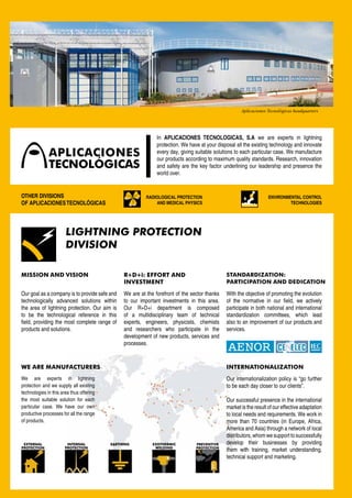


Aplicaciones Tecnológicas S.A. specializes in lightning protection, offering innovative and high-quality solutions tailored to diverse needs through a network of support in over 70 countries. The company emphasizes research, development, and compliance with international standards to ensure safety and efficiency in their products and services. They provide risk assessment, training, and installation services, ensuring customer satisfaction while maintaining a strong commitment to environmental responsibility.


![Getting Started with Apache Spark: Big Data Made Simple [Free Meetup]](https://cdn.slidesharecdn.com/ss_thumbnails/apachesparkgettingstarted-260203175547-8361bcc3-thumbnail.jpg?width=640&height=640&fit=bounds)

