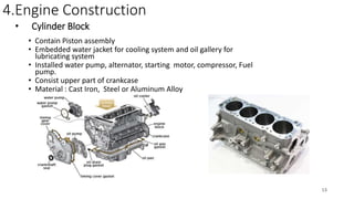
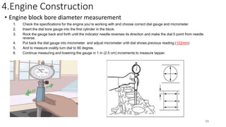
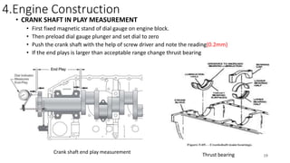
This document provides an overview of diesel engine components and systems. It discusses the key parts of an engine including the cylinder head, block, valves, pistons, crankshaft, and injectors. It also describes the working principles of a compression ignition engine. The document reviews the major engine systems like air intake, lubrication, cooling, and fuel. It provides details on maintenance procedures such as engine dismantling and component measurements.
2. Table of content
1. Engine Introduction
2. Compression Ignition Engine Working Principle
3. Major components
4. Engine dismantle procedure
5. Engine construction
1. Cylinder head
2. Cylinder Block
6. Air in take system
7. Lubrication system
8. Cooling system
9. Fuel system
2
4. 2. Compression Ignition Engine Working Principle
• 1 to 2 : isentropic compression (blue)
• Piston moves from BDC to TDC position. Air is compressed
isentropically inside the cylinder. Pressure of air increases from
p1 to p2
• 2 to 3 : reversible constant pressure heat
• (red)
• Heat is added at constant pressure from external heat source.
Volume increases from V2 to V3
• 3 to 4 : isentropic expansion (yellow)
• Compressed and heated air is expanded isentropically inside
cylinder. Piston is forced from TDC
• to BDC in the cylinder. Pressure of air decreases from p3 to p4
• 4 to 1 : reversible constant volume cooling
• (green)
• Heat is rejected at constant volume (V4 = V1). Pressure decreases
from P4 to P1
4
7. Major Engine Components
Valve assembly
Injectors
Cylinder block
Air intake system
flywheel
Piston assembly
Connecting rod
Crank case
Cylinder head
7
8. 7.Engine Dismantle Procedure
Warning: When using a steam cleaner wear protective clothing and safety
Glasses or a face shield. Hot steam can cause serious potential injuries.
• The engine was dismantled first from the main body and taken out including starter
motor, tappet cover, gasket and oil is drained.
• The bolts and nuts fixing the engine block were removed.
• Then the engine was tilted and fan pully, vibration damper, belt tensioner, cylinder
head crankshaft pully, crankshaft, camshaft, pistons are taken out simultaneously.
• All the parts of the engine were dismantled and cleaned thoroughly by oil.
• Measurements and readings are taken simultaneously.
8
9. 4.Engine Construction
• Cylinder head
It is the upper part of engine contain valve driving mechanism, installed
intake and exhaust manifold, and jointed by upper head gasket with cylinder
block.
Head gasket
Injector
Valve Driving Mechanism
9
10. 4.Engine Construction
• Cylinder Head Removal and Tightening Procedure
Follow the flowing sequence while removing head (18mm).
In this process specified torque is not given
To install head first tighten all the screw with 60 Nm torque
By following the given pattern, then by 120NM, and bolts
17,9,1,8,16 by 180NM torque and turn all of the bolt 90 degree
10
11. 4.Engine Construction
• Valve clearance and valve timing adjustment
1. First with the help of timing pin lock the cam shaft which will make ensure that 1 piston at TDC
2. And adjust valve clearance of valve(1,2,3,6,7,10)
3. First loosen tightening nut and adjust clearance with the help of ( filler gauge for intake0.25/0.5 mm)
4. Now after adjustment of (1,2,3,6,7,10) rotate flywheel 180 degree and adjust valve clearance of rest of valves
Valve clearance adjustment Valve timing adjustment
Valve over lapping
Valve timing diagram 11
13. • Cylinder Block
• Contain Piston assembly
• Embedded water jacket for cooling system and oil gallery for
lubricating system
• Installed water pump, alternator, starting motor, compressor, Fuel
pump.
• Consist upper part of crankcase
• Material : Cast Iron, Steel or Aluminum Alloy
4.Engine Construction
13
14. Engine Construction
• Engine block
• Engine oil pump
• Water pump
• Fuel pump (1 5 3 6 2 4)
• Oil filter and Engine Oil cooler
• Fuel Pump gear and Cam shaft gear
Engine oil pump Water pump
Engine oil filter and cooler 14
15. 4.Engine Construction
• Engine block bore diameter measurement
1. Check the specifications for the engine you’re working with and choose correct dial gauge and micrometer
2. Insert the dial bore gauge into the first cylinder in the block.
3. Rock the gauge back and forth until the indicator needle reverses its direction and make the dial 0 point from needle
reverse.
4. Put back the dial gauge into micrometer and adjust micrometer until dial shows previous reading.(102mm)
5. And to measure ovality turn dial to 90 degree.
6. Continue measuring and lowering the gauge in 1 in (2.5 cm) increments to measure tapper.
15
16. 4.Engine Construction
• Piston and crank shaft assembly
• Piston
• 2 compression rings and oil ring (120)
• Piston pin
• Connecting rod
• Crank shaft
16
17. 4.Engine Construction
• Piston ring assembly and Piston ring end gap
Top ring: (0.4-0.7)mm
Intermediate: (0.25-0.55)mm
Oil ring: (0.25-0.55)mm
Piston ring assembly Top ring: no measurement
Intermediate: (0.075-0.150)mm
Oil ring: (0.04-0.13)mm
Piston ring end gap Clearance in groove
17
19. 4.Engine Construction
• CRANK SHAFT IN PLAY MEASUREMENT
• First fixed magnetic stand of dial gauge on engine block.
• Then preload dial gauge plunger and set dial to zero
• Push the crank shaft with the help of screw driver and note the reading(0.2mm)
• If the end plays is larger than acceptable range change thrust bearing
Crank shaft end play measurement
Thrust bearing 19
20. Air in take system
Air filter
Turbo charger
Inter cooler
Turbo charger working
20
22. 5.Engine Lubrication System
lubrication system function
• Lubricant dissipate heat from moving parts ( e.g. cooling of piston)
• Lubricant reduce friction between two moving parts and reduce power loss form friction.
• Lubricant prevent corrasion, because it creates thin oil film on the surface and break contact with air.
• Lubricant clean by removing small metal chips, and carbon residue.
• Lubricant also absorb vibration and dampen sound that are coming from moving parts.
Engine oil pump
Engine oil filter working
22
23. 6.Engine Cooling System
• Water Cooling System
• Components
Radiator
Radiator Cooling Fans
Pressure Cap & Reserve Tank
Water Pump
Thermostat
Heater Core
• Removing excessive heat
from engine
• Maintain engine operating
temperature
• And maintain maximum
efficiency of engine
Radiator temperature distribution
23
25. 8.Fuel system
Distributor Type Fuel Injection Pump System
Fuel Tank
Fuel Filter
Fuel Feed Pump
Fuel Injection Pump
Injector
25
26. 8.Fuel system
Fuel timing adjustment and fuel line adjustment
• First lock camshaft gear with the help
of timing pin.
• It makes sure that 1 cylinder is at the
TCD of compression stroke.
• And match the 0 mark on cam gear
and c mark in pump gear.
D 1
E 5
F 3
A 6
B 2
C 4
FUEL LINE ADJUST MENT
26