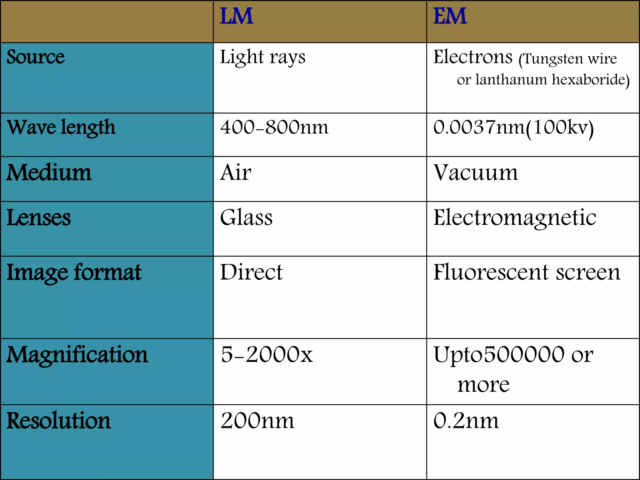
Electron Microscope
AIIMS, New Delhi
DR. SHANKAR BASTAKOTI, Junior Resident Pathology , 3rd year
 Electron microscope are scientific
instruments that use a beam of highly
energetic electrons to examine objects on
a very fine scale.
 Yield the morphological and
tophographical information.
History
 Invention: Max Knoll and Ernst Ruska at
the Berlin Technische Hochschule in
1931.
 Overcame the barrier to higher
resolution that had been imposed by the
limitations of visible light.
 The ultimate goal was atomic resolution -
the ability to see atoms .
 By late 1930s electron microscopes with
theoretical resolutions of 10 nm were
being designed and produced.
 By 1944 further reduced to 2 nm.
Increase in accelerating voltage of
electron beam accounted for
improvement in resolution.
 Improvements in electron lens
technology minimized aberrations and
better vacuum systems and brighter
electron guns.
Increasing resolution of electron
microscopes - main driving force
Intro to Electron Microscopy
 Similar to optical microscopy except with electrons rather
than photons
 Used to image samples with a resolution of 10 Å
 Can image many different structural geometries
 Mostly limited by radiation damage from the electron
beam
Working Principle
Electron microscopy works exactly like
optical microscope except that they use
a focused beam of electrons instead of
light to “image” specimen and gain
information as to its structure and
composition.
Eletron beam is only capable of
penetrating around 100 nm, to obtain
high quality image and optimise
resolution - 80nm thickness.
Basic steps:
 A streams of electrons is formed by electron
source and accelerated towards specimen
using a positive electrical potential.
 This stream is confined and focused using
metal apertures and magnetic lenses into a thin
monochromatic beam.
 This beam is focused onto the sample using a
magnetic lens.
 Interactions occur inside the irradiated sample
affecting the electron beam. These interactions
and effects are directed and transformed into
the image.
Types of electron microscope
1. Transmission electron microscope
(TEM)
2.Scanning electron microscope (SEM)
3. High voltage electron microscope
(HVEM)
4. Scanning Transmission electron
microscope (STEM).
Components of Electron
Microscope
Thermionic Electron Gun
Heated filament produces electrons
( Tungsten or Lanthanum
Hexaboride)
Electrons drawn towards an anode
An aperture in the anode creates a
beam
Condenser lenses
Objective lenses
Diffraction or intermediate lenses
Projection lenses
Focusing screen
Fluorescent viewing screen
Plate camera
Objective aperture
Vacuum
When electron beam is bombarded on fluorescent screen, it emits photon of
visible light. The photo film contain silver halide, elec. beam liberates free silver,
which after developing produce negative image, further processed to produce
positive film.
(Forms initial enlarged image)
(forms final
enlarged image)
(Determine electron beam diameter)
Handle with care!
 Size is large
 Temperature - 20 ⁰ C
 Never be near electromagnetic fields
 Basements are best
 Cost benefit ratio
 Expertise
Specimen handling
To preserve ultrastructure of cell,
completely immersed and fix as soon as
possible.
Dissection can be done which facilitates
penetration of fixatives and processing
reagents.
Preparation:
 Fixative: 2.5% Gluteraldehyde
(crosslinking mechanism involving amine
group of lysine and other amino acids
through formation of pyridine
intermediaries): 2-6 hours.
 Size of the tissue: 1-2 mm.
Block preparation for TEM:
 Washing: fixed tissues are washed in
phosphate buffer ( nontoxic and work
well in most tissues) of PH 7.2 (kept at
4oc overnight).
 Post fixation (secondary fixative):
1% osmium tetroxide solution (preserve
lipids) for 2 hour at 4⁰c, wash tissues with
phosphate buffer after post fixing and then
with distill water.
 Dehydration: by various grade of alcohol
at 4⁰c (30%, 50%, 70%, 80%, 90%..2
changes of 15 minute each).
 Clearing by propylene oxide.
Embedding:
Epoxy resin: cross linking creates three
dimensional uniform polymer, very little
shrinkage (<2%) and once complete is
permanent.
Four components: Monomeric resin , Hardener,
Accelerator and Plasticizer.
 Polymerization: The embedded blocks are
kept at 50⁰C in a oven for 24 hour. The
temperature is then raised to 60⁰C and the
embedded tissues are kept for 48 hr to
complete polymerization.
 Blocks are ready for sectioning.
Ultramicrotomy
 Glass knife
 Diamond knife
Higher angle knives (up to 55°) are best
suited to cutting hard materials, while
softer blocks respond better to shallower
(35°) angle knives.
Trough fluids
 Simplest and most suitable
fluid in section collecting troughs:
distilled or deionized water.
 Ensure that correct level of fluid is
added. If level is too high, fluid will be
drawn over cutting edge and down
back of knife, thereby preventing
proper sectioning. If level is too low,
sections will accumulate on cutting
edge and will not float out.
Block trimming
Semi-thin sections
 Semi-thin (or ‘survey’) sections
:screened to select areas for thin
sectioning. Semi-thin sections are
usually cut on a glass knife.
 Commonly, semi-thin sections are cut at
between 0.5 and 1.0 μm from trimmed or
partly trimmed blocks using
ultramicrotome and a glass knife.
 Various cationic dyes, including
methylene blue, azure B and crystal
violet, can be used for this purpose,
although most common is toluidine blue
Collection of sections
 Ultra-thin sections mounted onto specimen
grids. Grids measure 3.05 mm in diameter
and are made of conductive material,
commonly copper, nickel or gold.
 200 square mesh commonly used, although
slotted, parallel bar and hexagonal patterns
are also standard.
 As electrons cannot pass through metal grid
bars, choice of grid becomes a compromise
between support for sections (better with
grids of smaller mesh size) and relative
proportion of exposed section (better with
grids of larger mesh size).
 After collecting sections, grids should
be placed on filter paper in a lidded
container, such as a Petri dish, and
allowed to dry completely before
staining.
 Specimens should be clearly labeled
(on the filter paper) - extremely fragile.
 Storage box: not only afford protection
but also provide a means of identifying
individual grids.
Staining
 Uranyl salt : 10 min
 Lead salt: 10 min
LM EM
Source Light rays Electrons (Tungsten wire
or lanthanum hexaboride)
Wave length 400-800nm 0.0037nm(100kv)
Medium Air Vacuum
Lenses Glass Electromagnetic
Image format Direct Fluorescent screen
Magnification 5-2000x Upto500000 or
more
Resolution 200nm 0.2nm
E/M L/M
Fixative- Glutaraldehyde 2.5% 10% formalin
Post fixation in osmium tetra oxide not required
Embedding – Epoxy resins paraffin wax
Section cutting – ultra microtome microtome
Blade – diamond/ glass iron/ steel
Ultrathin sections 3-4 microns
Section is collected on GRID (3.05mm D),
made up of copper, gold, palladium, Mb etc. Better the grid =
smaller is mesh size (100- 300).
Glass slides
Staining- Uranyl acetate & lead
citrate
H&E
Black-electron dense Blue & red
Role of EM in Pathology
 Diagnostic EM: To solve immediate
diagnostic problem
 Study of etiopathogenesis - Not of
immediate diagnostic relevance
 Research - many new entities
described
Application
THANK YOU

Electron Microscope

  • 1.
    Electron Microscope AIIMS, NewDelhi DR. SHANKAR BASTAKOTI, Junior Resident Pathology , 3rd year
  • 2.
     Electron microscopeare scientific instruments that use a beam of highly energetic electrons to examine objects on a very fine scale.  Yield the morphological and tophographical information.
  • 3.
    History  Invention: MaxKnoll and Ernst Ruska at the Berlin Technische Hochschule in 1931.  Overcame the barrier to higher resolution that had been imposed by the limitations of visible light.  The ultimate goal was atomic resolution - the ability to see atoms .
  • 4.
     By late1930s electron microscopes with theoretical resolutions of 10 nm were being designed and produced.  By 1944 further reduced to 2 nm. Increase in accelerating voltage of electron beam accounted for improvement in resolution.  Improvements in electron lens technology minimized aberrations and better vacuum systems and brighter electron guns. Increasing resolution of electron microscopes - main driving force
  • 5.
    Intro to ElectronMicroscopy  Similar to optical microscopy except with electrons rather than photons  Used to image samples with a resolution of 10 Å  Can image many different structural geometries  Mostly limited by radiation damage from the electron beam
  • 6.
    Working Principle Electron microscopyworks exactly like optical microscope except that they use a focused beam of electrons instead of light to “image” specimen and gain information as to its structure and composition. Eletron beam is only capable of penetrating around 100 nm, to obtain high quality image and optimise resolution - 80nm thickness.
  • 7.
    Basic steps:  Astreams of electrons is formed by electron source and accelerated towards specimen using a positive electrical potential.  This stream is confined and focused using metal apertures and magnetic lenses into a thin monochromatic beam.  This beam is focused onto the sample using a magnetic lens.  Interactions occur inside the irradiated sample affecting the electron beam. These interactions and effects are directed and transformed into the image.
  • 9.
    Types of electronmicroscope 1. Transmission electron microscope (TEM) 2.Scanning electron microscope (SEM) 3. High voltage electron microscope (HVEM) 4. Scanning Transmission electron microscope (STEM).
  • 10.
    Components of Electron Microscope ThermionicElectron Gun Heated filament produces electrons ( Tungsten or Lanthanum Hexaboride) Electrons drawn towards an anode An aperture in the anode creates a beam
  • 11.
    Condenser lenses Objective lenses Diffractionor intermediate lenses Projection lenses Focusing screen Fluorescent viewing screen Plate camera Objective aperture Vacuum When electron beam is bombarded on fluorescent screen, it emits photon of visible light. The photo film contain silver halide, elec. beam liberates free silver, which after developing produce negative image, further processed to produce positive film. (Forms initial enlarged image) (forms final enlarged image) (Determine electron beam diameter)
  • 13.
    Handle with care! Size is large  Temperature - 20 ⁰ C  Never be near electromagnetic fields  Basements are best  Cost benefit ratio  Expertise
  • 14.
    Specimen handling To preserveultrastructure of cell, completely immersed and fix as soon as possible. Dissection can be done which facilitates penetration of fixatives and processing reagents.
  • 15.
    Preparation:  Fixative: 2.5%Gluteraldehyde (crosslinking mechanism involving amine group of lysine and other amino acids through formation of pyridine intermediaries): 2-6 hours.  Size of the tissue: 1-2 mm. Block preparation for TEM:  Washing: fixed tissues are washed in phosphate buffer ( nontoxic and work well in most tissues) of PH 7.2 (kept at 4oc overnight).
  • 16.
     Post fixation(secondary fixative): 1% osmium tetroxide solution (preserve lipids) for 2 hour at 4⁰c, wash tissues with phosphate buffer after post fixing and then with distill water.  Dehydration: by various grade of alcohol at 4⁰c (30%, 50%, 70%, 80%, 90%..2 changes of 15 minute each).  Clearing by propylene oxide.
  • 17.
    Embedding: Epoxy resin: crosslinking creates three dimensional uniform polymer, very little shrinkage (<2%) and once complete is permanent. Four components: Monomeric resin , Hardener, Accelerator and Plasticizer.  Polymerization: The embedded blocks are kept at 50⁰C in a oven for 24 hour. The temperature is then raised to 60⁰C and the embedded tissues are kept for 48 hr to complete polymerization.  Blocks are ready for sectioning.
  • 18.
    Ultramicrotomy  Glass knife Diamond knife Higher angle knives (up to 55°) are best suited to cutting hard materials, while softer blocks respond better to shallower (35°) angle knives.
  • 20.
    Trough fluids  Simplestand most suitable fluid in section collecting troughs: distilled or deionized water.  Ensure that correct level of fluid is added. If level is too high, fluid will be drawn over cutting edge and down back of knife, thereby preventing proper sectioning. If level is too low, sections will accumulate on cutting edge and will not float out.
  • 21.
  • 22.
    Semi-thin sections  Semi-thin(or ‘survey’) sections :screened to select areas for thin sectioning. Semi-thin sections are usually cut on a glass knife.  Commonly, semi-thin sections are cut at between 0.5 and 1.0 μm from trimmed or partly trimmed blocks using ultramicrotome and a glass knife.  Various cationic dyes, including methylene blue, azure B and crystal violet, can be used for this purpose, although most common is toluidine blue
  • 23.
    Collection of sections Ultra-thin sections mounted onto specimen grids. Grids measure 3.05 mm in diameter and are made of conductive material, commonly copper, nickel or gold.  200 square mesh commonly used, although slotted, parallel bar and hexagonal patterns are also standard.  As electrons cannot pass through metal grid bars, choice of grid becomes a compromise between support for sections (better with grids of smaller mesh size) and relative proportion of exposed section (better with grids of larger mesh size).
  • 26.
     After collectingsections, grids should be placed on filter paper in a lidded container, such as a Petri dish, and allowed to dry completely before staining.  Specimens should be clearly labeled (on the filter paper) - extremely fragile.  Storage box: not only afford protection but also provide a means of identifying individual grids.
  • 28.
    Staining  Uranyl salt: 10 min  Lead salt: 10 min
  • 31.
    LM EM Source Lightrays Electrons (Tungsten wire or lanthanum hexaboride) Wave length 400-800nm 0.0037nm(100kv) Medium Air Vacuum Lenses Glass Electromagnetic Image format Direct Fluorescent screen Magnification 5-2000x Upto500000 or more Resolution 200nm 0.2nm
  • 32.
    E/M L/M Fixative- Glutaraldehyde2.5% 10% formalin Post fixation in osmium tetra oxide not required Embedding – Epoxy resins paraffin wax Section cutting – ultra microtome microtome Blade – diamond/ glass iron/ steel Ultrathin sections 3-4 microns Section is collected on GRID (3.05mm D), made up of copper, gold, palladium, Mb etc. Better the grid = smaller is mesh size (100- 300). Glass slides Staining- Uranyl acetate & lead citrate H&E Black-electron dense Blue & red
  • 33.
    Role of EMin Pathology  Diagnostic EM: To solve immediate diagnostic problem  Study of etiopathogenesis - Not of immediate diagnostic relevance  Research - many new entities described
  • 34.
  • 42.

Editor's Notes

  • #5 Theoretical resolution of an optical light microscope -200 nm.)