The document discusses transformers and provides details about:
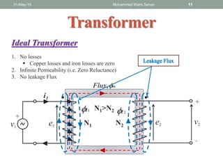
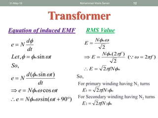
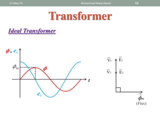
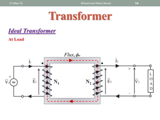
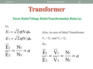
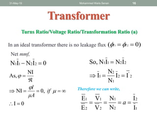
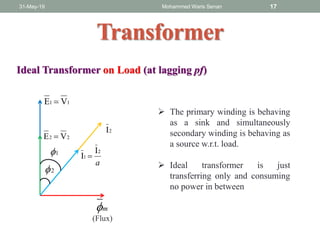
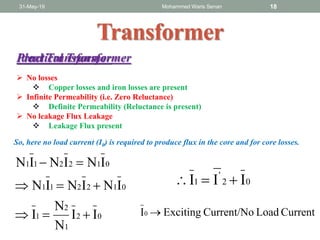
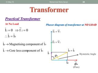
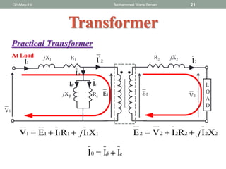
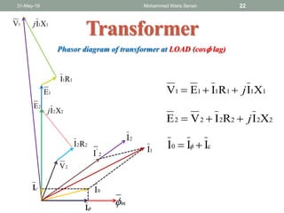
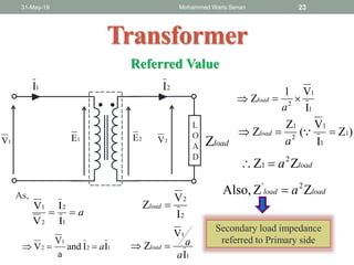
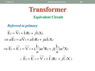
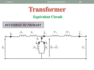
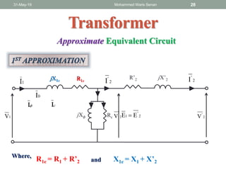
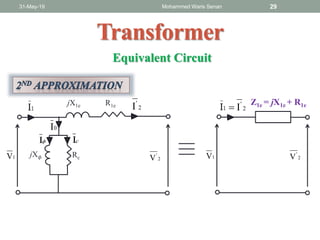
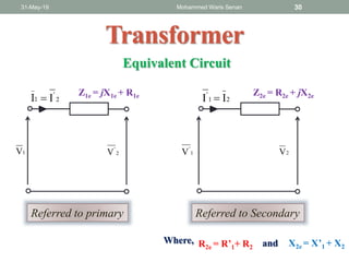
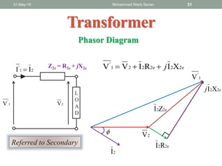
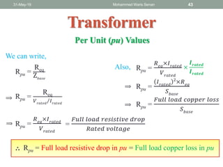
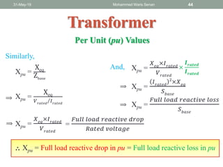
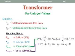
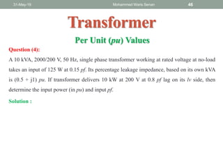
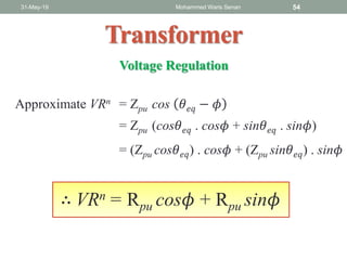
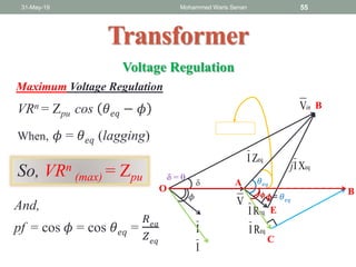
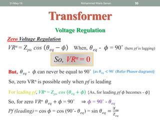
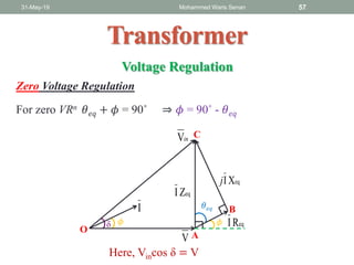
- Ideal and practical transformer characteristics and equations
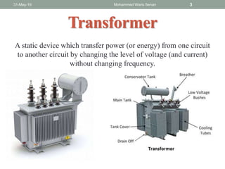
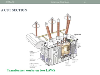
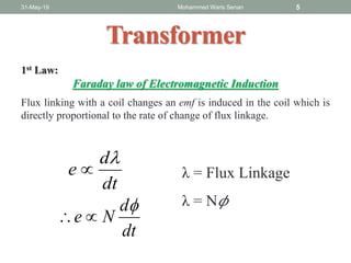
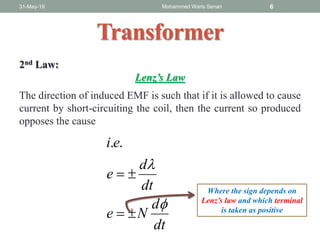
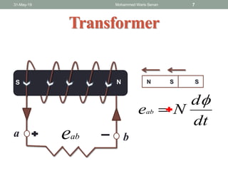
- Transformer operation is based on Faraday's law of induction and Lenz's law
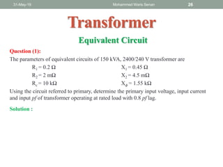
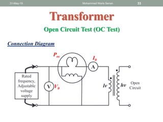
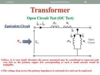
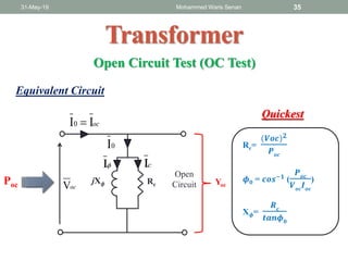
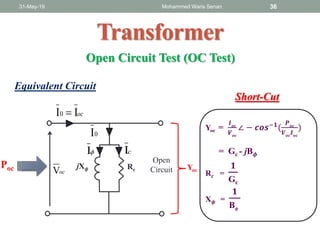
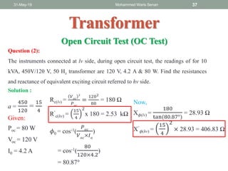
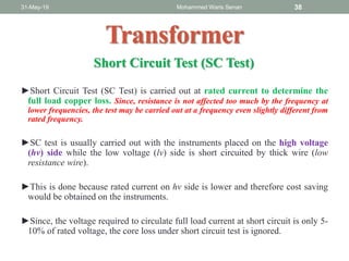
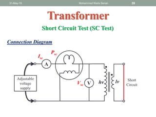
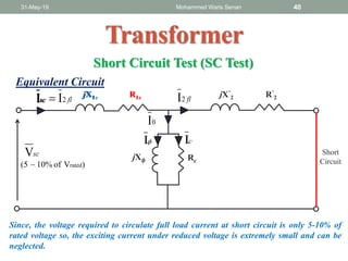
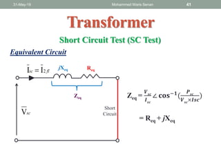
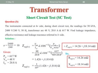
- Open circuit and short circuit tests are used to determine a transformer's core losses and impedance without actual loading