This document provides an overview of basic electrical engineering concepts including charge, current, voltage, circuits, network elements, sources, superposition theorem, Thevenin's theorem, Norton's theorem, and maximum power transfer theorem. Key points include:
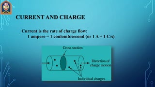
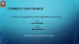
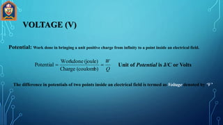
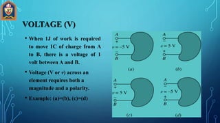
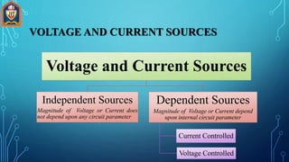
- Current is the rate of charge flow measured in amperes. Voltage is the potential difference measured in volts.
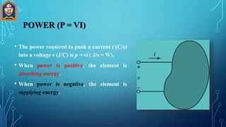
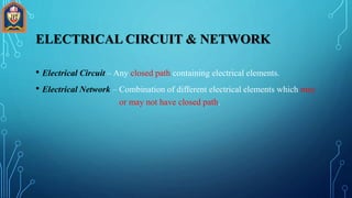
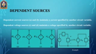
- Circuits contain both active elements that supply energy (sources) and passive elements that consume energy.
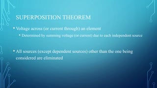
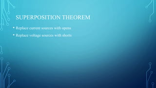
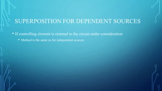
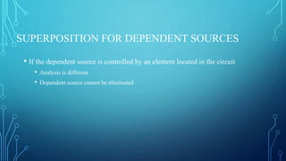
- Superposition and source transformation theorems allow analysis of circuits containing multiple sources.
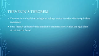
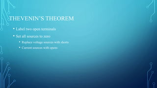
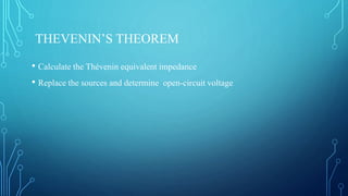
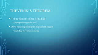
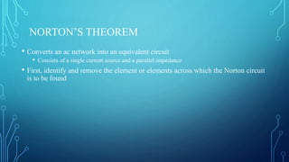
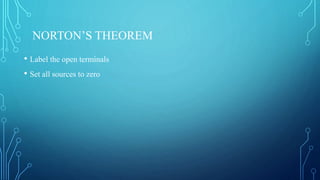
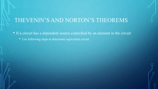
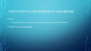
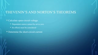
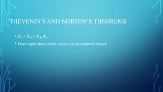
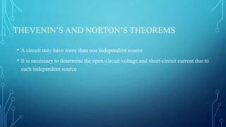
- Thevenin's and Norton's theorems convert circuits to equivalent circuits with a single voltage or current source.
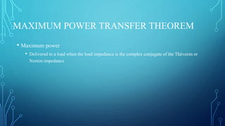
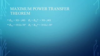
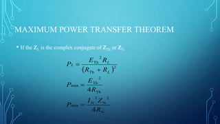
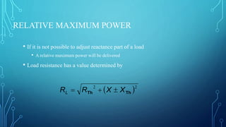
- Maximum power is delivered to a load when