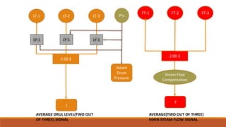
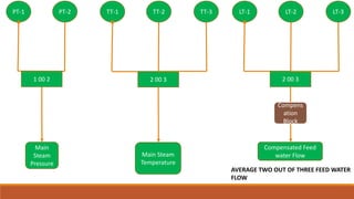
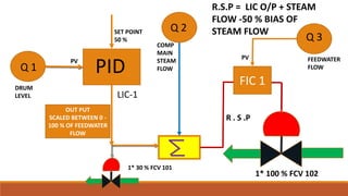
CLOSED LOOP
CONTROL
ASHVANI SHUKLA
BOILER DRUM LEVEL
CONTROL
LT-2 LT-3LT-1
2 00 3
AVERAGE DRUL LEVEL(TWO OUT
OF THREE) SIGNAL
AVERAGE(TWO OUT OF THREE)
MAIN STEAM FLOW SIGNAL
L
FT-2 FT-3FT-1
2 00 3
F
LY-1 LY-1 LY-1
Prs
Steam
Drum
Pressure
Steam Flow
Compensation
AVERAGE TWO OUT OF THREE FEED WATER
FLOW
LT-2 LT-3LT-1
2 00 3
Compensated Feed
water Flow
TT-2 TT-3TT-1
2 00 3
Main Steam
Temperature
Compens
ation
Block
PT-2PT-1
1 00 2
Main
Steam
Pressure
Q 1 PID
SET POINT
50 %
OUT PUT
SCALED BETWEEN 0 -
100 % OF FEEDWATER
FLOW
Q 2
COMP
MAIN
STEAM
FLOW
DRUM
LEVEL
1* 100 % FCV 102
R.S.P = LIC O/P + STEAM
FLOW -50 % BIAS OF
STEAM FLOW
1* 30 % FCV 101
LIC-1
FIC 1
Q 3
R . S .P
FEEDWATER
FLOW
PV
PV
Introduction of Closed loop Control/Drum
level Control
OBJECTIVE:-
Drum is a closed vessel which is filled with Treated water during the Normal operation of Boiler
or it act as a water storage tank for boiler tubes. Water is used to Generate the Steam and
Cooling of water tube for protection from Departure Nucleate Boiling. So we have to maintain
the adequate level of water during the normal operation of boiler. In steam drum there are
some physical phenomenon are happening during the load change of boiler. Due to load change
Pressure goes suddenly up and sudden down So level will fluctuate and will not maintain
properly at desired level. It is called shrink and swell effect. When sudden load increase then
stem flow increases and pressure drops inside the drum and level stars swelling vice versa when
steam flow decreased the pressure will rise then and level will goes down called shrink effect. So
we are not able to maintain the adequate level of water level inside the drum. Formerly we are
using the single element and two element level control philosophy to control the level of steam
drum.
Continue……
But during the sudden load change above technologies are failed to maintain the adequate
water level in steam drum. So due to these constrains we are using the three element control
philosophy for steam drum level control.
It has some important physical system and parameters which are used to control the process.
1.FEEDWATER CONTROL
The BFP Discharge pressure controller is responsible for maintaining enough pressure in the BFP
Discharge Header.
The objective of the feed water control system is to balance the boiler steam and feed water
flows in proportion to steam out flow to maintain a safe water level in the steam drum at any
boiler load condition
Continue…..
Drum level control is typical three-element control consisting of drum level, feed water flow and
main steam flow parameter. It is used to maintain drum level by sensing steam load variation in
main steam flow and by regulating Feed water flow through feed water control valves.
The feed water controls valves that both typically have 100 % capacity can be substitute each
other with one 30% capacity control valve (start up control valve).The feed water start up valve
controller represents the single element portion of the feed water control loop that is used
during the start up of the boiler. When the boiler generates steam load of 30 % MCR, the feed
water control is switched to three element mode (1E to 3E switch over is manual) and controls
shall be done with 100% control valves.
The control loop is designed in such a way that 100% CV can be operate in single element by
Operator selection
Continue…..
Feed water Start up Valve Control 30 %( FCV-101)
The controller objective is to maintain drum water level at a required set point during the start up of
the boiler. A pressure compensated drum water level measurement is used as the process variable for
the controller.
The feed water start up valve controller (LIC-101) compares the drum water level measurement to the
operator adjustable set point and generates an output that sets the position of the feed water start
up control valve( 30 % ) resulting in the change in feed water flow rate and drum water level.
Controller (LIC-101) action is reverse type.
Continue…..
Feed water Main Control Valve (FCV-102)
The controller objective is to maintain drum water level at a required set point during the
operational load i.e. (>30%) of the boiler. A pressure compensated drum water level
measurement is used as the process variable for the controller.
The feed water main valve controller (LIC-101) compares the drum water level measurement to
the operator adjustable set point and generates an output that add or subtract with the (e.g.
load changes) the balance between the steam and feed water flow rates and final value sets the
position of the feed water Main control valve resulting in the change in feed water flow rate and
drum water level.
Continue…..
◦ Drum Level Control
Drum level is measured using three nos. of level transmitters. The 2 out of 3 level signals ( LT-
1,2,3) is compensated for drum pressure individually before the 2 out of 3 block. Drum pressure
is measured with the help of drum pressure transmitter.
As the characteristics of drum pressure Vs drum level is non- linear. Drum pressure is passed
through function generator (for generation of non- linear curve) the output of which is
multiplied with drum level signal to generate compensated level signal.
The values (as per enclosed annexure) for the curve are to be fed in PLC.
Continue….
For Boiler protection, level switches very high and very low will be derived in PLC using level
transmitters 2 out of 3 logic for high-low alarm (LAHH-01 & LALL-01) will be generated in PLC, very
high and very low drum level will be used for trip logic.
The remote water level indication from Hydra step will be displayed near by the Feed water flow
control station.
The steam drum level controller (LIC-101 ) objective is to maintain drum water level at a required set
point during the operating of the boiler. If for any reason (e.g. load changes) the balance between
the steam and feed water flow rates is altered, a change in the boilers water inventory is affected that
is indicated by the change in the amount of water stored in the drum.
So at that point we summate the LIC-101 output with steam flow and subtract the bias of steam flow
to generate the remote set point for FIC-101.Depends upon the error generated by FIC-101 we
control the position of FCV-102 to maintain the feed water flow.

Drun level control

  • 1.
  • 2.
  • 3.
    LT-2 LT-3LT-1 2 003 AVERAGE DRUL LEVEL(TWO OUT OF THREE) SIGNAL AVERAGE(TWO OUT OF THREE) MAIN STEAM FLOW SIGNAL L FT-2 FT-3FT-1 2 00 3 F LY-1 LY-1 LY-1 Prs Steam Drum Pressure Steam Flow Compensation
  • 4.
    AVERAGE TWO OUTOF THREE FEED WATER FLOW LT-2 LT-3LT-1 2 00 3 Compensated Feed water Flow TT-2 TT-3TT-1 2 00 3 Main Steam Temperature Compens ation Block PT-2PT-1 1 00 2 Main Steam Pressure
  • 5.
    Q 1 PID SETPOINT 50 % OUT PUT SCALED BETWEEN 0 - 100 % OF FEEDWATER FLOW Q 2 COMP MAIN STEAM FLOW DRUM LEVEL 1* 100 % FCV 102 R.S.P = LIC O/P + STEAM FLOW -50 % BIAS OF STEAM FLOW 1* 30 % FCV 101 LIC-1 FIC 1 Q 3 R . S .P FEEDWATER FLOW PV PV
  • 6.
    Introduction of Closedloop Control/Drum level Control OBJECTIVE:- Drum is a closed vessel which is filled with Treated water during the Normal operation of Boiler or it act as a water storage tank for boiler tubes. Water is used to Generate the Steam and Cooling of water tube for protection from Departure Nucleate Boiling. So we have to maintain the adequate level of water during the normal operation of boiler. In steam drum there are some physical phenomenon are happening during the load change of boiler. Due to load change Pressure goes suddenly up and sudden down So level will fluctuate and will not maintain properly at desired level. It is called shrink and swell effect. When sudden load increase then stem flow increases and pressure drops inside the drum and level stars swelling vice versa when steam flow decreased the pressure will rise then and level will goes down called shrink effect. So we are not able to maintain the adequate level of water level inside the drum. Formerly we are using the single element and two element level control philosophy to control the level of steam drum.
  • 7.
    Continue…… But during thesudden load change above technologies are failed to maintain the adequate water level in steam drum. So due to these constrains we are using the three element control philosophy for steam drum level control. It has some important physical system and parameters which are used to control the process. 1.FEEDWATER CONTROL The BFP Discharge pressure controller is responsible for maintaining enough pressure in the BFP Discharge Header. The objective of the feed water control system is to balance the boiler steam and feed water flows in proportion to steam out flow to maintain a safe water level in the steam drum at any boiler load condition
  • 8.
    Continue….. Drum level controlis typical three-element control consisting of drum level, feed water flow and main steam flow parameter. It is used to maintain drum level by sensing steam load variation in main steam flow and by regulating Feed water flow through feed water control valves. The feed water controls valves that both typically have 100 % capacity can be substitute each other with one 30% capacity control valve (start up control valve).The feed water start up valve controller represents the single element portion of the feed water control loop that is used during the start up of the boiler. When the boiler generates steam load of 30 % MCR, the feed water control is switched to three element mode (1E to 3E switch over is manual) and controls shall be done with 100% control valves. The control loop is designed in such a way that 100% CV can be operate in single element by Operator selection
  • 9.
    Continue….. Feed water Startup Valve Control 30 %( FCV-101) The controller objective is to maintain drum water level at a required set point during the start up of the boiler. A pressure compensated drum water level measurement is used as the process variable for the controller. The feed water start up valve controller (LIC-101) compares the drum water level measurement to the operator adjustable set point and generates an output that sets the position of the feed water start up control valve( 30 % ) resulting in the change in feed water flow rate and drum water level. Controller (LIC-101) action is reverse type.
  • 10.
    Continue….. Feed water MainControl Valve (FCV-102) The controller objective is to maintain drum water level at a required set point during the operational load i.e. (>30%) of the boiler. A pressure compensated drum water level measurement is used as the process variable for the controller. The feed water main valve controller (LIC-101) compares the drum water level measurement to the operator adjustable set point and generates an output that add or subtract with the (e.g. load changes) the balance between the steam and feed water flow rates and final value sets the position of the feed water Main control valve resulting in the change in feed water flow rate and drum water level.
  • 11.
    Continue….. ◦ Drum LevelControl Drum level is measured using three nos. of level transmitters. The 2 out of 3 level signals ( LT- 1,2,3) is compensated for drum pressure individually before the 2 out of 3 block. Drum pressure is measured with the help of drum pressure transmitter. As the characteristics of drum pressure Vs drum level is non- linear. Drum pressure is passed through function generator (for generation of non- linear curve) the output of which is multiplied with drum level signal to generate compensated level signal. The values (as per enclosed annexure) for the curve are to be fed in PLC.
  • 12.
    Continue…. For Boiler protection,level switches very high and very low will be derived in PLC using level transmitters 2 out of 3 logic for high-low alarm (LAHH-01 & LALL-01) will be generated in PLC, very high and very low drum level will be used for trip logic. The remote water level indication from Hydra step will be displayed near by the Feed water flow control station. The steam drum level controller (LIC-101 ) objective is to maintain drum water level at a required set point during the operating of the boiler. If for any reason (e.g. load changes) the balance between the steam and feed water flow rates is altered, a change in the boilers water inventory is affected that is indicated by the change in the amount of water stored in the drum. So at that point we summate the LIC-101 output with steam flow and subtract the bias of steam flow to generate the remote set point for FIC-101.Depends upon the error generated by FIC-101 we control the position of FCV-102 to maintain the feed water flow.