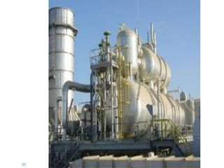
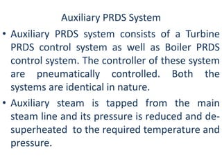
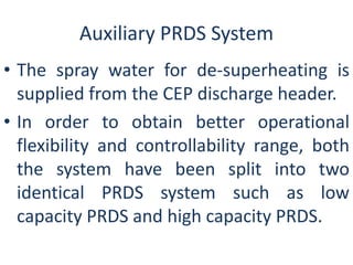
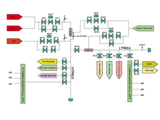
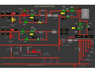
APRDS SYSTEM 
BY 
SHARAVAN TRIPATHI 
JIPT
Auxiliary PRDS System 
• Auxiliary PRDS system consists of a Turbine 
PRDS control system as well as Boiler PRDS 
control system. The controller of these system 
are pneumatically controlled. Both the 
systems are identical in nature. 
• Auxiliary steam is tapped from the main 
steam line and its pressure is reduced and de-superheated 
to the required temperature and 
pressure.
Auxiliary PRDS System 
• The spray water for de-superheating is 
supplied from the CEP discharge header. 
• In order to obtain better operational 
flexibility and controllability range, both 
the system have been split into two 
identical PRDS system such as low 
capacity PRDS and high capacity PRDS.
Auxiliary PRDS System Contd.. 
• The low capacity is of 30% of that of the high 
capacity line. 
• Each system comprises of the pressure 
controller, one de-superheater and one spray 
water flow controller. 
• We shall henceforth call the Turbine PRDS 
system as TAS and the Boiler PRDS system as 
BAS.
System Description- High Capacity 
• High capacity PRDS comprises of steam pressure 
reducing control valve, motorized upstream isolating 
valve, downstream manual isolating valve, one spray 
water temperature control valve and one de-superheater. 
• A motorized regulating globe valve is provided in 
bypass line of, which can be operated remote manually 
in case of mal-operation of the pressure control valve. 
• A motorized bypass globe valve is provided for spray 
water control valve , which can be operated remote 
manually in case of mal-operation of spray water 
control valve.
System Description- Low Capacity 
• Low capacity PRDS comprises of steam pressure reducing 
control valve, motorized upstream isolating valve, 
downstream manual isolating valve, one spray water 
temperature control valve and one desuperheater. 
• A motorized regulating globe valve is provided in bypass 
line of, which can be operated remote manually in case of 
mal-operation of pressure reducing control valve. 
• A motorized bypass globe valve is provided for spray water 
control valve, which can be operated remote manually in 
case of mal-operation of spray water control valve.
TAS/BAS Pressure/ Temperature Control 
• The auxiliary steam pressure control valve supplies 
steam to TAS/BAS header by maintaining TAS/BAS 
line pressure constant at the set point (11 kg/cm2). 
Downstream pressure of PRDS valve is taken as 
controlled pressure. 
• The auxiliary PRDS spray water flow control valve 
(CD) maintains the TAS / BAS line temperature 
constant at the set point (2600C for TAS & 2200C for 
BAS). The downstream temperature of PRDS valve is 
taken as controlled temperature.
Selection of HT & LT PRDS 
• During unit start up auxiliary steam for turbine is supplied 
to Deaerator initial heating & pegging, Turbine Gland 
Sealing. To meet this high demand of auxiliary steam HT 
PRDS should be put into service. 
• After unit synchronization and at about 30 to 40% of unit 
load deaerator pegging is supplied from CRH / turbine 
extraction line (CAP) and pegging from TRDS is cut out. At 
about 40% unit load also, turbine gland sealing supply valve 
from TPRDS closes as turbine becomes self-sealing 
condition.
Uses of Aux Steam at various locations of plant 
LTPRDS:- 
1) VAM 
2) FO heating 
3) HFO Atomizing 
4) Mill Inerting 
5) Wet steam washing 
HTPRDS:- 
1) Turbine Gland Sealing 
2) Deaerator Pagging 
3) APH soot blowing
Vapor Absorber Machine (VAM)
Vapor Absorber Machine (VAM) 
• Absorption refrigeration systems replace the 
compressor with a generator and an absorber. 
Refrigerant enters the evaporator in the form of a 
cool, low-pressure mixture of liquid and vapor (4). 
• Heat is transferred from the relatively warm water 
to the refrigerant, causing the liquid refrigerant to 
boil. Using an analogy of the vapor compression 
cycle, the absorber acts like the suction side of the 
compressor—it draws in the refrigerant vapor (1) to 
mix with the absorbent. The pump acts like the 
compression process itself—it pushes the mixture 
of refrigerant and absorbent up to the high-pressure 
side of the system.
Vapor Absorber Machine (VAM) 
• The generator acts like the discharge of the 
compressor—it delivers the refrigerant vapor (2) to 
the rest of the system. 
• The refrigerant vapor (2) leaving the generator 
enters the condenser, where heat is transferred to 
water at a lower temperature, causing the 
refrigerant vapor to condense into a liquid. This 
liquid refrigerant (3) then flows to the expansion 
device, which creates a pressure drop that reduces 
the pressure of the refrigerant to that of the 
evaporator. The resulting mixture of liquid and 
vapor refrigerant (4) travels to the evaporator to 
repeat the cycle.
How Absorption Machine Works 
• Absorption system employs heat and a 
concentrated salt solution (lithium bromide) to 
produce chilled water. In its simplest design the 
absorption machine consists of 4 basic components: 
1. Generator 
2. Condenser 
3. Evaporator 
4. Absorber
Function of Components 
Generator: 
• The purpose of the generator is to deliver the refrigerant 
vapor to the rest of the system. 
• It accomplishes this by separating the water (refrigerant) from 
the lithium bromide-and-water solution. 
• In the generator, a high-temperature energy source, typically 
steam or hot water, flows through tubes that are immersed in 
a dilute solution of refrigerant and absorbent. 
• The solution absorbs heat from the warmer steam or water, 
causing the refrigerant to boil (vaporize) and separate from 
the absorbent solution. 
• As the refrigerant is boiled away, the absorbent solution 
becomes more concentrated. The concentrated absorbent 
solution returns to the absorber and the refrigerant vapor 
migrates to the condenser.
Condenser: 
• The purpose of condenser is to condense the 
refrigerant vapors. Inside the condenser, cooling 
water flows through tubes and the hot refrigerant 
vapor fills the surrounding space. 
• As heat transfers from the refrigerant vapor to the 
water, refrigerant condenses on the tube surfaces. 
The condensed liquid refrigerant collects in the 
bottom of the condenser before traveling to the 
expansion device. 
• The cooling water system is typically connected to 
a cooling tower. Generally, the generator and 
condenser are contained inside of the same shell.
Expansion Device: 
• From the condenser, the liquid refrigerant flows 
through an expansion device into the evaporator. The 
expansion device is used to maintain the pressure 
difference between the high-pressure (condenser) and 
low-pressure (evaporator) sides of the refrigeration 
system by creating a liquid seal that separates the high-pressure 
and low pressure sides of the cycle. 
• As the high-pressure liquid refrigerant flows through 
the expansion device, it causes a pressure drop that 
reduces the refrigerant pressure to that of the 
evaporator. This pressure reduction causes a small 
portion of the liquid 
• refrigerant to boil off, cooling the remaining refrigerant 
to the desired evaporator temperature. The cooled 
mixture of liquid and vapor refrigerant then flows into 
the evaporator.
Absorber: 
• Inside the absorber, the refrigerant vapor is absorbed 
by the lithium bromide solution. As the refrigerant 
vapor is absorbed, it condenses from a vapor to a 
liquid, releasing the heat it acquired in the evaporator. 
• The absorption process creates a lower pressure within 
the absorber. This lower pressure, along with the 
absorbent’s affinity for water, induces a continuous 
flow of refrigerant vapor from the evaporator. In 
addition, the absorption process condenses the 
refrigerant vapors and releases the heat removed from 
the evaporator by the refrigerant. The heat released 
from the condensation of refrigerant vapors and their 
absorption in the solution is removed to the cooling 
water that is circulated through the absorber tube 
bundle.
• As the concentrated solution absorbs more and 
more refrigerant; its absorption ability decreases. 
The weak absorbent solution is then pumped to the 
generator where heat is used to drive off the 
refrigerant. The hot refrigerant vapors created in 
the generator migrate to the condenser. The cooling 
tower water circulating through 
• the condenser turns the refrigerant vapors to a 
liquid state and picks up the heat of condensation, 
which it rejects to the cooling tower. The liquid 
refrigerant returns to the evaporator and completes 
the cycle.
FO Heating 
Viscosity 
• The viscosity of a fluid is a measure of its internal 
resistance to flow. Viscosity depends on 
temperature and decreases as the temperature 
increases. 
• Any numerical value for viscosity has no meaning 
unless the temperature is also specified. 
• Viscosity is measured in Stokes / Centistokes. 
Sometimes viscosity is also quoted in Engler, 
Saybolt or Redwood.
• Each type of oil has its own temperature - viscosity 
relationship. The measurement of viscosity is made 
with an instrument called Viscometer. 
• Viscosity is the most important characteristic in the 
storage and use of fuel oil. It influences the degree 
of pre-heat required for handling, storage and 
satisfactory atomization. If the oil is too viscous, it 
may become difficult to pump, hard to light the 
burner, and tough to operate. 
• Poor atomization may result in the formation of 
carbon deposits on the burner tips or on the walls. 
Therefore pre-heating is necessary for proper 
atomization.
Pressure Reduce Steam.
OIL GUN 
HFO NOZZLE 
VALVE SCAVENGE 
ATOMISING 
STEAM VALVE 
VALVE 
AB ELEVATION 
CD ELEVATION 
EF ELEVATION 
Atomizing Steam Scheme 
Oil Gun Connection 
HFO Automizing
Oil Gun on Elevation AB
Oil Gun on Elevation CD & Above
Mill Inerting system
Wet Steam Washing 
• During operation, deposits occur on the turbine 
blading to a greater or lesser degree depending on 
the steam purity [1] and the pressures and 
temperatures of the operating steam. These 
deposits cause a reduction of the turbine generator 
unit’s efficiency due to: 
Changes in the flow profiles 
• Thicker boundary layers in the steam 
• flow as a result of rough surfaces.
• In extreme cases the flow area of turbine may get reduced 
with consequent reduction in the maximum possible steam 
flow through the turbine, and corresponding output. Choking 
of blade flow path can be detected on the basis of internal 
efficiency measurement 
• If deposit leads to an increase in stage pressures, the 
maximum stage pressures shown in the Technical Data should 
not be exceeded. If necessary, the output must be reduceds. 
• water-insoluble, silicate deposits occur in a temperature 
range between 500°C and 350°C. Alkali silicates and silicic acid 
are deposited between 350°C and 60°C. 
• Salt deposits occur at temperatures ranging from 480°C to the 
blading stages where condensation begins. Salt deposits are 
water-soluble and can be removed by steam washing with 
saturated steam. Depending on their composition, silicate 
deposits are either water-soluble (e.g. alkali silicates) or occur 
as a hard Water-insoluble coating. In latter case the deposits 
can only be removed mechanically during overhauls.
Steam Washing of IP Turbine 
• All stop and control valves and all valves in the extraction 
lines remain closed during steam washing of the IP turbine. 
• Any isolating valves present upstream of the feed water 
heaters must also be closed. 
• The drains from the IP turbine between the reheat control 
valves and the IP outlet, the extraction valves or the swing 
check valves in the extraction lines must be vented during 
steam washing only to the extent required to allow the 
condensate arising to drain off whilst preventing excessive 
loss of steam. 
• All other drains from the turbine generator must be full open. 
After the saturated steam line (Fig.1, item 2) has been joined 
up at the connection points (3), the washing steam can be 
routed into the IP turbine, from there via the cross-around 
lines to the IP turbine and then to the condenser.
Steam Washing of HP Turbine 
• The main control valves must be open during steam washing 
of the HP turbine. 
• All drains (7, 8) from the HP turbine situated between the 
main stop valves and the HP outlet may be vented during 
steam washing only to the extent required to allow the 
condensate arising to drain off while preventing excessive loss 
of steam. 
• All other drains particularly those in the cold reheat line, must 
be fully open. 
• Local drainage may also be provided so that no steam can 
enter the Reheater of the Boiler, if at all possible. After the 
steam line (6) has been joined up at the connection points (3), 
the stream can be routed into the HP turbine. 
• The steam leaving the HP turbine is exhausted to the 
condenser via the drains (9). The condensate is discharged 
and samples are taken to determine the salt content as 
described in steam washing of IP turbine, the completion 
criteria remaining same.
Gland Sealing System
FUNCTION 
• This system ensures the sealing of glands in HP, IP and 
LP turbine under various load conditions. The turbine 
glands are self seal type (refer gland sealing scheme). 
Upto 40% load, steam from an auxiliary source through 
valve (MAW10AA001) is taken to seal all the HP,IP and 
LP glands. 
• During this period the valve (MAW50AA001) 
connecting this header to condenser is kept closed. 
After 40% load, seal steam valve (MAW10AA001) is 
closed and the leak steam valve (MAW50AA001) is 
opened. 
• Pipings are so sized that the leak off steam from front 
and rear ends of HP turbine goes to the condenser 
through the valve (MAW50AA001), while steam from 
the two IP glands is utilised for sealing the LP glands, 
thus avoiding the use of a desuperheater.
• The leak off steam and air from the last chambers of 
each rotor is sucked into a gland cooler. Building up of 
vacuum in the condenser is the first step during start 
up. For building up vacuum, it is necessary to seal the 
turbine glands by supplying steam to the shaft through 
the valve (MAW10AA001). 
• The control system opens the gland steam supply valve 
(MAW10AA001) until the pressure in the header 
acquires a preset value. Subsequently when the set 
picks up load, the pressure of steam inside HP and IP 
turbine builds up resulting in the leakage of steam from 
the turbine into gland steam supply header which in 
turn would result in increase of pressure in the header. 
• The controller gradually closes the gland steam supply 
valve (MAW10AA001) and opens gland leak off valve 
(MAW50AA001), if required.
49 
Why Deaeration? 
Corrosion in boilers is caused by three factors: 
1. Feed water temperature 
2. Feed water pH value 
3. Feed water oxygen content 
Temperature and pH value influence the aggressiveness of 
corrosion. The higher the temperature, and the lower the pH 
value the increased aggressiveness of the feed water. The 
dissolved oxygen content of the feed water is a large factor in 
determining the amount of corrosion that will take place. The 
presence of oxygen, and other non-condensable gases, in the feed 
water is a major cause of corrosion in the feed water piping, 
boiler, and condensate handling equipment.
50 
Why Deaeration? 
• Reduce corrosion by dissolved gas: oxygen, 
carbon dioxide. Oxygen is the most 
aggressive even in small concentrations. 
• Sources of oxygen: makeup water, 
condensate return system. 
• Pitting corrosion. Degree of oxygen attack 
depends on concentration of dissolved 
oxygen, the pH and the temperature of the 
water.
Removal of oxygen, carbon dioxide and other 
non-condensable gases from feed water. 
51 
What is Deaeration?
52 
Deaerator Principles 
Deaeration is the mechanical removal of dissolved gases from the boiler feed 
water. There are three principles that must be met in the design of any 
deaerator. 
1. The incoming feed water must be heated to the full saturation temperature, 
corresponding to the steam pressure maintained inside the deaerator. This 
will lower the solubility of the dissolved gases to zero. 
2. The heated feed water must be mechanically agitated. This is accomplished in 
a tray deaerator by first spraying the water in a thin film into a steam 
atmosphere. Creating a thin film reduces the distance, the gas bubble has to 
travel to be released from the water. Next, the water is cascaded over a bank 
of slotted trays, further reducing the surface tension of the water. This allows 
for the removal of any gases not liberated by the initial spraying. 
3. Adequate steam supply must be passed through the water, in both the spray 
section and the tray section to sweep out the gases from the water.
The easiest way to de-aerate is to force steam into the feed water, 
this action is called scrubbing. Scrubbing raises the water 
temperature causing the release of O2 and CO2 gases that are 
then vented from the system. In boiling section steam is used to 
"scrub" the feed water as 
(1)steam is essentially devoid of O2 and CO2, 
(2)steam is readily available and 
(3)steam adds the heat required to complete the reaction. 
53 
Deaerator Principles
For efficient operation, de-aerating equipment must satisfy the 
following requirements: 
(1)Heating of the feed water: The operating temperature in the unit 
should be saturation temperature. If this temperature and 
pressure cannot be economically achieved then it is important to 
get as close to it as possible. 
(2)Agitation decreases the time and heat energy necessary to 
remove dissolved gases from the water. 
(3)Maximization of surface area by finely dispersing the water to 
expose maximum surface area to the steam. This enables the 
water to be heated to saturation temperature quicker and 
reduces the distance the gases have to travel to be liberated. 
(4)The liberated gases must be vented to allow their escape from the 
system as they are released. 
54
55
56
57
58 
DEAERATION 
Oxygen reacts with water ( H20 ) to give ( OH 
- ) ION 
Fe = Fe+ + e- 
O2 + 2H2O + 4e- = 4OH-Fe+ 
+ 2OH- = Fe(OH)2 
2Fe + O2 + 2H2O = Fe(OH)2
59 
DEAERATION 
Carbon dioxide is an acidic gas and 
could form carbonic acid with water, 
carbonic acid liberates H+ ions that 
attacks on metal. 
CO2 + H20  H2CO3 
 H+ + HCO 
2H+ + 2e- = H2 
- 
3
60 
TYPES OF DEAERATION 
1. Physical deaeration. 
2. Chemical deaeration. 
PRINCIPAL FOR PHYSICAL DEAERATION 
The principle of deaeration is based on the following laws 
• HENERY’S LAW 
• DALTON’S LAW OF PARTIAL PRESSURE
61 
Dalton’s Law of Partial Pressure 
It states that the pressure in a container having a 
mixture of a gas and vapour, is the sum of partial 
pressure of the vapour at the common 
temperature and the partial pressure of the gas, 
at any point inside.
62 
HENERY’S LAW 
• The mass of gas with a definite mass of liquid, 
which will dissolve at a given temperature, is 
directly proportional to the partial pressure of 
the gas in contact with the liquid. 
• This hold with in the close limit for gases which 
don’t unite chemically with water.
Decreasing the partial pressure of the gas in water 
may be achieved by following methods: 
63 
Use of another gas to remove the undesirable 
gases e.g. Nitrogen can be used to remove 
oxygen. 
Decreasing the total pressure so as to 
approach the vapour pressure of the water. 
Increasing the vapour pressure by heating 
the water
(A) According to working pressure under which they 
operate: 
 Vacuum deaerator 
 Atmospheric deaerator 
 High pressure deaerator 
64 
Classification of Deaerator
65 
Vacuum Deaerator
66 
Classification of Deaerator 
(B) Also deaerator can be classified in accordance with the 
mode of steam-water distribution: 
Atomizing ( spray ) type 
Tray type 
Film type ( combination of both spray and tray 
type)
67 
Tray Type Deaerator
68 
Tray Type Deaerators 
These are composed of a deaerating section and a feed water storage 
section. Incoming water is sprayed through a perforated distribution pipe into 
a steam atmosphere where it is atomized. There it is heated to within a few 
degrees of the saturation temperature of the steam. Most of the non-condensable 
gases are released to the steam as the water enters the unit. The 
water then cascades through the tray section, breaking into fine droplets, 
which immediately contact incoming steam. The steam heats the water to the 
saturation temperature of the steam and removes all but a trace of 
oxygen. Deaerated water falls to the feed water storage section below and is 
protected from recontamination by a blanket of steam. As the non-condensable 
gases are liberated, they as well as a small amount of steam are 
vented to atmosphere. It is essential that sufficient venting is provided at all 
times or deaeration will be incomplete.
69 
Tray Type Deaerator
70 
Trays
71 
Spray Type Deaerators
72 
Spray Type Deaerators 
The spray-type deaerators do not use trays for dispersion of the water. In this 
case, spring loaded nozzles located in the top of the unit spray water into a steam 
atmosphere which is heated to within a few degrees of the saturation temperature 
of the steam. Most of the non-condensable gases are released to the steam, and 
the heated water falls to a water seal and drains to the lowest section of the steam 
scrubber. The water is scrubbed by large quantities of steam and heated to the 
saturation temperature prevailing at this point. The intimate steam to water 
contact achieved in the scrubber efficiently strips the water of dissolved gases. As 
the steam-water mixture rises in the scrubber, a slight pressure loss causes the 
deaerated water temperature to remain a few degrees below the inlet steam 
saturation temperature. The deaerated water overflows from the steam scrubber 
to the storage section below. The steam, after flowing through the scrubber, 
passes up into the spray heater section to heat the incoming water. Most of the 
steam condenses in the spray section to become part of the deaerated water. A 
small portion of the steam, vented to atmosphere, removes non-condensable 
gases from the system.
73 
Spray Type Deaerators
Spray Valve 
74
75 
Counter & Parallel Flow Deaerator
1. In this design, the inlet water is sprayed into a steam atmosphere 
spray nozzles. 
2. This action heats the water to liberate most of the dissolved gases. 
3. This flows down through water seals for distribution over the tray 
bank, which serve two functions. 
4. First they prevent gases liberated in the initiate heating, from 
entering the tray bank. 
5. Second they direct the steam to flow down through the trays, 
before entering the upper heating section. 
6. The main function of the tray bank is to remove the remaining 
amounts of dissolved gases, not liberated in the initial heating. 
76 
Parallel Down Flow
7. Since very little, or no heating takes place in the trays, the entire 
volume of steam is used to scrub out the remaining gases. 
8. The trays are slotted, and provide a great amount of spilling 
edge. 
9. This allows for a great amount of water surface area to be 
exposed to the steam. 
10.Water and steam flow downward through the trays. 
11.The steam, after exiting the tray bank, steam is condensed by 
the colder inlet water, and a small amount is vented to 
atmosphere, along with the dissolved gases. 
77 
Parallel Down Flow
78 
Packed Column Type
1. Inlet water is sprayed into a steam atmosphere through a 
variable orifice & spring loaded spray nozzle. 
2. water heating liberate dissolved gases & heated water 
flows down onto a distribution plate, which evenly 
distributes the water over the entire cross-sectional area 
of the tower packing. 
3. As the water flows down through the distribution plate it 
enters a steam chest area, where it is further heated by 
up flowing steam and more of the dissolved gases are 
liberated. 
79 
Packed Tower
1. Remaining dissolved gases are removed when the water 
flows down from the steam chest and then down through 
the packing tower. 
2. The packing tower exposes a greater surface area of the 
water; while up flowing steam completes the deaeration 
process. The water leaving the bottom of the packing 
tower is given a final scrubbing of steam. 
3. The steam, entering the deaerator from below the packing 
tower, is introduced through a fixed orifice steam 
distributor. This steam distributor directs high velocity 
steam through the down flowing water leaving the bottom 
of the packing tower. 
80 
Packed Tower
81 
Deaerator Functions 
Deaerator has to meet following needs. 
 It does deaeration 
 Acts as a feed water heater. 
 Acts as a storage tank (reservoir) 
 Accept the leak-off flows from the BFP. 
 Accept the H.P. Heater drains. 
 Heat the tank content from cold to provide 
hot deaerated water for unit start-up. 
 Ensure NPSH for BFP
82 
DEAERATING RATIO 
O2 Content in Condensate at 
inlet to deaerator 
= 6 
O2 Content in feed water at outlet S.T.
TECHNICAL PARTICULARS OF DEAERATOR 
1. Type Tray with external vent condenser 
2. Design Pressure Kg/cm2 7.4 
3. Design Temperature OC 250 
4. Hydraulic Test Pressure Kg/cm2 11.1 
5. Storage capacity M3 90 
6. No. of perforated trays 5 
83
84 
Operating Conditions of Deaerator 
 Temperature of deaerated water must be equal to 
saturation temp. of water corresponding to the 
pressure at which deaerator operates. 
 Sufficient heating steam must be delivered to the 
deaerator to ensure continuous boiling of water 
undergoing deaeration. 
 The feed water charge to deaerator must be 
disintegrated into fine droplets to ensure better heat – 
transfer 
 Deaerator must be provided with sufficient venting to 
purge all the non-condensing gases out of the system 
and to ensure minimum partial Pressure of these gases 
in the upper part of the deaerator.
Causes of High O2/CO2 Concentration 
 Inadequate deaerator vent leading to accumulation of 
non-condensing gases and increase in their partial 
pressure. 
 High feed-water flow rate. 
 Delivery of O2 - containing condensate directly into 
85 
the storage tank. 
 Frequent pressure drop in the deaerator. 
 Faulty deaerator internals. 
 Delivery of relatively “cold” flows with higher O2 - 
content to deaerator.
While the most efficient mechanical deaerators 
reduce oxygen to very low levels (.005cc/l or 5 
ppb), even trace amounts of oxygen may cause 
corrosion damage to a system. Consequently, 
good operating practice requires removal of that 
trace oxygen with a chemical oxygen scavenger 
such as sodium sulfite or hydrazine. 
86
87 
Chemical Deaeration 
The addition of an oxygen scavenging chemical (Sodium Sulphite or Hydrazine) will 
remove the remaining oxygen and prevent corrosion. 
Na2SO3 + O2 = Na2SO4 
Sodium Sulphite Oxygen Sodium Sulphate 
Now obsolete, as it increases the total dissolved solids. 
Modern Practice: Hydrazine is used for chemical Deaeration. 
N2H4 + O2 = N2 + 2H2O 
3N2H4 = 4NH3 + N2 
Additional ammonia reacts with 
2NH3 + CO2 + H2O = (NH4)2CO3 
(acidic) Ammonium Carbonate (Neutral)
88 
FST - Deaerator
89
Disadvantages of Counter Flow Deaerators 
• Inability to deliver 0.007 ppb outlet quality in applications with a 
low inlet water temperature, or when 100% make-up is 
required. 
• Low tray loading. This reduces the flow rating for a given 
diameter deaerator vs. a parallel down flow unit. 
• High vent rate. This reduces operating efficiency 
Advantages of Counter Flow Deaerators 
• The counter flow deaerator is cheaper to manufacture. 
• The higher capacity and the ability to perform under varying steam 
and water conditions make the parallel down flow (and packed 
tower for smaller applications) design competitive, and the only 
logical choice. 
90
Disadvantages of Atomizer Deaerators 
• Inability to deliver 7 ppb outlet quality when plant conditions 
vary from design specifications. Requires constant plant 
conditions. 
• Failure rate of the atomizer valve, and maintenance required to 
keep it operating properly. 
Advantages of Atomizer Deaerators 
• 1. Low cost 
• 2. Low overall height 
The atomizer type deaerator is only effective when applied to an application with no plant or 
process swings. Along with the maintenance required, this type deaerator, while inexpensive, 
has only limited applications. 
91
Disadvantages of Parallel Down Flow 
• More complicated design, resulting in slightly higher cost. 
Advantages of Parallel Down Flow 
• Time proven design 
• Thousands of installations worldwide 
• Design suitable for small to medium size plants 
• Can meet outlet guarantees at varying plant conditions. 
• High tray loading, resulting in higher outlet capacity for any 
given diameter. 
• Large tray spilling edge, resulting in high deaerating efficiency 
• Low vent rate, resulting in increased operating efficiency. 
92
93 
Disadvantages of Packed tower 
• Height requirement 
• Typically considered for small size plants. 
Advantages of Packed tower 
• Low cost 
• Low maintenance 
• Ability to handle varying plant conditions 
• This design can meet the requirements for a reliable 
deaerator capable of producing completely deaerated 
water for small plants. Packed tower design includes 
multi-stage deaeration, to deliver top performance.
CORROSION is defined as the destruction of a metal by chemical or 
electromechanical reaction with its environment. Corrosion dramatically 
increases maintenance costs and can cause unnecessary safety risks. It will 
occur when levels of oxygen or carbon dioxide are high, where pH values are 
low, where contact occurs between dissimilar metals and in corrosive 
atmospheres. Corrosion is an electrochemical process in which electricity flows 
through a solution of ions between areas of metal. Deterioration occurs when 
the current leaves the negatively charged metal or anode and travels through 
the solution to the positively charged metal or cathode, completing an 
electrical circuit in much the same manner as a battery cell. The anode and the 
cathode can be different metals or areas of the same metal. Corrosion occurs 
when there is a difference in the electrical potential between them. 
SCALE is a very hard substance that adheres directly to heating surfaces 
forming a layer of insulation. This layer of insulation will decrease heat transfer 
efficiency. Scale also results in metal fatigue/failure from overheating, energy 
waste, high maintenance costs and unnecessary safety risks. A one-sixteenth 
inch thickness of scale in a fire tube boiler can result in a 12.5% increase in fuel 
consumption. 
94
FOULING occurs when a restriction develops in piping and equipment 
passageways and results in inefficient water flow. The fouling of boiler room 
equipment directly impacts energy efficiencies and cost of operations. 
FOAMING is a condition in which concentrations of soluble salts, aggravated 
by grease, suspended solids or organic matter, create frothy bubbles or foam 
in the steam space of a boiler. When these bubbles collapse it creates a 
liquid that is carried over into the steam system. Foaming degrades steam 
quality and in some cases can create a water slug that is discharged into the 
steam lines. 
CAUSTIC GAUGING will occur when there is a high concentration of alkaline 
salts (a pH value of 11 or greater) that will liberate hydrogen absorbed by 
the iron in the steel. It will be more evident in high temperature areas of the 
boiler's waterside and manifests itself in the form of hairline cracks. 
HYDROGEN EMBRITTLEMENT occurs in the event of lower pH value of the 
water in evaporator 
95
Thank you

Aprds system

  • 1.
    APRDS SYSTEM BY SHARAVAN TRIPATHI JIPT
  • 2.
    Auxiliary PRDS System • Auxiliary PRDS system consists of a Turbine PRDS control system as well as Boiler PRDS control system. The controller of these system are pneumatically controlled. Both the systems are identical in nature. • Auxiliary steam is tapped from the main steam line and its pressure is reduced and de-superheated to the required temperature and pressure.
  • 3.
    Auxiliary PRDS System • The spray water for de-superheating is supplied from the CEP discharge header. • In order to obtain better operational flexibility and controllability range, both the system have been split into two identical PRDS system such as low capacity PRDS and high capacity PRDS.
  • 6.
    Auxiliary PRDS SystemContd.. • The low capacity is of 30% of that of the high capacity line. • Each system comprises of the pressure controller, one de-superheater and one spray water flow controller. • We shall henceforth call the Turbine PRDS system as TAS and the Boiler PRDS system as BAS.
  • 7.
    System Description- HighCapacity • High capacity PRDS comprises of steam pressure reducing control valve, motorized upstream isolating valve, downstream manual isolating valve, one spray water temperature control valve and one de-superheater. • A motorized regulating globe valve is provided in bypass line of, which can be operated remote manually in case of mal-operation of the pressure control valve. • A motorized bypass globe valve is provided for spray water control valve , which can be operated remote manually in case of mal-operation of spray water control valve.
  • 8.
    System Description- LowCapacity • Low capacity PRDS comprises of steam pressure reducing control valve, motorized upstream isolating valve, downstream manual isolating valve, one spray water temperature control valve and one desuperheater. • A motorized regulating globe valve is provided in bypass line of, which can be operated remote manually in case of mal-operation of pressure reducing control valve. • A motorized bypass globe valve is provided for spray water control valve, which can be operated remote manually in case of mal-operation of spray water control valve.
  • 9.
    TAS/BAS Pressure/ TemperatureControl • The auxiliary steam pressure control valve supplies steam to TAS/BAS header by maintaining TAS/BAS line pressure constant at the set point (11 kg/cm2). Downstream pressure of PRDS valve is taken as controlled pressure. • The auxiliary PRDS spray water flow control valve (CD) maintains the TAS / BAS line temperature constant at the set point (2600C for TAS & 2200C for BAS). The downstream temperature of PRDS valve is taken as controlled temperature.
  • 10.
    Selection of HT& LT PRDS • During unit start up auxiliary steam for turbine is supplied to Deaerator initial heating & pegging, Turbine Gland Sealing. To meet this high demand of auxiliary steam HT PRDS should be put into service. • After unit synchronization and at about 30 to 40% of unit load deaerator pegging is supplied from CRH / turbine extraction line (CAP) and pegging from TRDS is cut out. At about 40% unit load also, turbine gland sealing supply valve from TPRDS closes as turbine becomes self-sealing condition.
  • 11.
    Uses of AuxSteam at various locations of plant LTPRDS:- 1) VAM 2) FO heating 3) HFO Atomizing 4) Mill Inerting 5) Wet steam washing HTPRDS:- 1) Turbine Gland Sealing 2) Deaerator Pagging 3) APH soot blowing
  • 12.
  • 13.
  • 14.
    Vapor Absorber Machine(VAM) • Absorption refrigeration systems replace the compressor with a generator and an absorber. Refrigerant enters the evaporator in the form of a cool, low-pressure mixture of liquid and vapor (4). • Heat is transferred from the relatively warm water to the refrigerant, causing the liquid refrigerant to boil. Using an analogy of the vapor compression cycle, the absorber acts like the suction side of the compressor—it draws in the refrigerant vapor (1) to mix with the absorbent. The pump acts like the compression process itself—it pushes the mixture of refrigerant and absorbent up to the high-pressure side of the system.
  • 15.
    Vapor Absorber Machine(VAM) • The generator acts like the discharge of the compressor—it delivers the refrigerant vapor (2) to the rest of the system. • The refrigerant vapor (2) leaving the generator enters the condenser, where heat is transferred to water at a lower temperature, causing the refrigerant vapor to condense into a liquid. This liquid refrigerant (3) then flows to the expansion device, which creates a pressure drop that reduces the pressure of the refrigerant to that of the evaporator. The resulting mixture of liquid and vapor refrigerant (4) travels to the evaporator to repeat the cycle.
  • 16.
    How Absorption MachineWorks • Absorption system employs heat and a concentrated salt solution (lithium bromide) to produce chilled water. In its simplest design the absorption machine consists of 4 basic components: 1. Generator 2. Condenser 3. Evaporator 4. Absorber
  • 18.
    Function of Components Generator: • The purpose of the generator is to deliver the refrigerant vapor to the rest of the system. • It accomplishes this by separating the water (refrigerant) from the lithium bromide-and-water solution. • In the generator, a high-temperature energy source, typically steam or hot water, flows through tubes that are immersed in a dilute solution of refrigerant and absorbent. • The solution absorbs heat from the warmer steam or water, causing the refrigerant to boil (vaporize) and separate from the absorbent solution. • As the refrigerant is boiled away, the absorbent solution becomes more concentrated. The concentrated absorbent solution returns to the absorber and the refrigerant vapor migrates to the condenser.
  • 21.
    Condenser: • Thepurpose of condenser is to condense the refrigerant vapors. Inside the condenser, cooling water flows through tubes and the hot refrigerant vapor fills the surrounding space. • As heat transfers from the refrigerant vapor to the water, refrigerant condenses on the tube surfaces. The condensed liquid refrigerant collects in the bottom of the condenser before traveling to the expansion device. • The cooling water system is typically connected to a cooling tower. Generally, the generator and condenser are contained inside of the same shell.
  • 23.
    Expansion Device: •From the condenser, the liquid refrigerant flows through an expansion device into the evaporator. The expansion device is used to maintain the pressure difference between the high-pressure (condenser) and low-pressure (evaporator) sides of the refrigeration system by creating a liquid seal that separates the high-pressure and low pressure sides of the cycle. • As the high-pressure liquid refrigerant flows through the expansion device, it causes a pressure drop that reduces the refrigerant pressure to that of the evaporator. This pressure reduction causes a small portion of the liquid • refrigerant to boil off, cooling the remaining refrigerant to the desired evaporator temperature. The cooled mixture of liquid and vapor refrigerant then flows into the evaporator.
  • 24.
    Absorber: • Insidethe absorber, the refrigerant vapor is absorbed by the lithium bromide solution. As the refrigerant vapor is absorbed, it condenses from a vapor to a liquid, releasing the heat it acquired in the evaporator. • The absorption process creates a lower pressure within the absorber. This lower pressure, along with the absorbent’s affinity for water, induces a continuous flow of refrigerant vapor from the evaporator. In addition, the absorption process condenses the refrigerant vapors and releases the heat removed from the evaporator by the refrigerant. The heat released from the condensation of refrigerant vapors and their absorption in the solution is removed to the cooling water that is circulated through the absorber tube bundle.
  • 26.
    • As theconcentrated solution absorbs more and more refrigerant; its absorption ability decreases. The weak absorbent solution is then pumped to the generator where heat is used to drive off the refrigerant. The hot refrigerant vapors created in the generator migrate to the condenser. The cooling tower water circulating through • the condenser turns the refrigerant vapors to a liquid state and picks up the heat of condensation, which it rejects to the cooling tower. The liquid refrigerant returns to the evaporator and completes the cycle.
  • 29.
    FO Heating Viscosity • The viscosity of a fluid is a measure of its internal resistance to flow. Viscosity depends on temperature and decreases as the temperature increases. • Any numerical value for viscosity has no meaning unless the temperature is also specified. • Viscosity is measured in Stokes / Centistokes. Sometimes viscosity is also quoted in Engler, Saybolt or Redwood.
  • 30.
    • Each typeof oil has its own temperature - viscosity relationship. The measurement of viscosity is made with an instrument called Viscometer. • Viscosity is the most important characteristic in the storage and use of fuel oil. It influences the degree of pre-heat required for handling, storage and satisfactory atomization. If the oil is too viscous, it may become difficult to pump, hard to light the burner, and tough to operate. • Poor atomization may result in the formation of carbon deposits on the burner tips or on the walls. Therefore pre-heating is necessary for proper atomization.
  • 31.
  • 34.
    OIL GUN HFONOZZLE VALVE SCAVENGE ATOMISING STEAM VALVE VALVE AB ELEVATION CD ELEVATION EF ELEVATION Atomizing Steam Scheme Oil Gun Connection HFO Automizing
  • 35.
    Oil Gun onElevation AB
  • 36.
    Oil Gun onElevation CD & Above
  • 39.
  • 40.
    Wet Steam Washing • During operation, deposits occur on the turbine blading to a greater or lesser degree depending on the steam purity [1] and the pressures and temperatures of the operating steam. These deposits cause a reduction of the turbine generator unit’s efficiency due to: Changes in the flow profiles • Thicker boundary layers in the steam • flow as a result of rough surfaces.
  • 41.
    • In extremecases the flow area of turbine may get reduced with consequent reduction in the maximum possible steam flow through the turbine, and corresponding output. Choking of blade flow path can be detected on the basis of internal efficiency measurement • If deposit leads to an increase in stage pressures, the maximum stage pressures shown in the Technical Data should not be exceeded. If necessary, the output must be reduceds. • water-insoluble, silicate deposits occur in a temperature range between 500°C and 350°C. Alkali silicates and silicic acid are deposited between 350°C and 60°C. • Salt deposits occur at temperatures ranging from 480°C to the blading stages where condensation begins. Salt deposits are water-soluble and can be removed by steam washing with saturated steam. Depending on their composition, silicate deposits are either water-soluble (e.g. alkali silicates) or occur as a hard Water-insoluble coating. In latter case the deposits can only be removed mechanically during overhauls.
  • 43.
    Steam Washing ofIP Turbine • All stop and control valves and all valves in the extraction lines remain closed during steam washing of the IP turbine. • Any isolating valves present upstream of the feed water heaters must also be closed. • The drains from the IP turbine between the reheat control valves and the IP outlet, the extraction valves or the swing check valves in the extraction lines must be vented during steam washing only to the extent required to allow the condensate arising to drain off whilst preventing excessive loss of steam. • All other drains from the turbine generator must be full open. After the saturated steam line (Fig.1, item 2) has been joined up at the connection points (3), the washing steam can be routed into the IP turbine, from there via the cross-around lines to the IP turbine and then to the condenser.
  • 44.
    Steam Washing ofHP Turbine • The main control valves must be open during steam washing of the HP turbine. • All drains (7, 8) from the HP turbine situated between the main stop valves and the HP outlet may be vented during steam washing only to the extent required to allow the condensate arising to drain off while preventing excessive loss of steam. • All other drains particularly those in the cold reheat line, must be fully open. • Local drainage may also be provided so that no steam can enter the Reheater of the Boiler, if at all possible. After the steam line (6) has been joined up at the connection points (3), the stream can be routed into the HP turbine. • The steam leaving the HP turbine is exhausted to the condenser via the drains (9). The condensate is discharged and samples are taken to determine the salt content as described in steam washing of IP turbine, the completion criteria remaining same.
  • 45.
  • 47.
    FUNCTION • Thissystem ensures the sealing of glands in HP, IP and LP turbine under various load conditions. The turbine glands are self seal type (refer gland sealing scheme). Upto 40% load, steam from an auxiliary source through valve (MAW10AA001) is taken to seal all the HP,IP and LP glands. • During this period the valve (MAW50AA001) connecting this header to condenser is kept closed. After 40% load, seal steam valve (MAW10AA001) is closed and the leak steam valve (MAW50AA001) is opened. • Pipings are so sized that the leak off steam from front and rear ends of HP turbine goes to the condenser through the valve (MAW50AA001), while steam from the two IP glands is utilised for sealing the LP glands, thus avoiding the use of a desuperheater.
  • 48.
    • The leakoff steam and air from the last chambers of each rotor is sucked into a gland cooler. Building up of vacuum in the condenser is the first step during start up. For building up vacuum, it is necessary to seal the turbine glands by supplying steam to the shaft through the valve (MAW10AA001). • The control system opens the gland steam supply valve (MAW10AA001) until the pressure in the header acquires a preset value. Subsequently when the set picks up load, the pressure of steam inside HP and IP turbine builds up resulting in the leakage of steam from the turbine into gland steam supply header which in turn would result in increase of pressure in the header. • The controller gradually closes the gland steam supply valve (MAW10AA001) and opens gland leak off valve (MAW50AA001), if required.
  • 49.
    49 Why Deaeration? Corrosion in boilers is caused by three factors: 1. Feed water temperature 2. Feed water pH value 3. Feed water oxygen content Temperature and pH value influence the aggressiveness of corrosion. The higher the temperature, and the lower the pH value the increased aggressiveness of the feed water. The dissolved oxygen content of the feed water is a large factor in determining the amount of corrosion that will take place. The presence of oxygen, and other non-condensable gases, in the feed water is a major cause of corrosion in the feed water piping, boiler, and condensate handling equipment.
  • 50.
    50 Why Deaeration? • Reduce corrosion by dissolved gas: oxygen, carbon dioxide. Oxygen is the most aggressive even in small concentrations. • Sources of oxygen: makeup water, condensate return system. • Pitting corrosion. Degree of oxygen attack depends on concentration of dissolved oxygen, the pH and the temperature of the water.
  • 51.
    Removal of oxygen,carbon dioxide and other non-condensable gases from feed water. 51 What is Deaeration?
  • 52.
    52 Deaerator Principles Deaeration is the mechanical removal of dissolved gases from the boiler feed water. There are three principles that must be met in the design of any deaerator. 1. The incoming feed water must be heated to the full saturation temperature, corresponding to the steam pressure maintained inside the deaerator. This will lower the solubility of the dissolved gases to zero. 2. The heated feed water must be mechanically agitated. This is accomplished in a tray deaerator by first spraying the water in a thin film into a steam atmosphere. Creating a thin film reduces the distance, the gas bubble has to travel to be released from the water. Next, the water is cascaded over a bank of slotted trays, further reducing the surface tension of the water. This allows for the removal of any gases not liberated by the initial spraying. 3. Adequate steam supply must be passed through the water, in both the spray section and the tray section to sweep out the gases from the water.
  • 53.
    The easiest wayto de-aerate is to force steam into the feed water, this action is called scrubbing. Scrubbing raises the water temperature causing the release of O2 and CO2 gases that are then vented from the system. In boiling section steam is used to "scrub" the feed water as (1)steam is essentially devoid of O2 and CO2, (2)steam is readily available and (3)steam adds the heat required to complete the reaction. 53 Deaerator Principles
  • 54.
    For efficient operation,de-aerating equipment must satisfy the following requirements: (1)Heating of the feed water: The operating temperature in the unit should be saturation temperature. If this temperature and pressure cannot be economically achieved then it is important to get as close to it as possible. (2)Agitation decreases the time and heat energy necessary to remove dissolved gases from the water. (3)Maximization of surface area by finely dispersing the water to expose maximum surface area to the steam. This enables the water to be heated to saturation temperature quicker and reduces the distance the gases have to travel to be liberated. (4)The liberated gases must be vented to allow their escape from the system as they are released. 54
  • 55.
  • 56.
  • 57.
  • 58.
    58 DEAERATION Oxygenreacts with water ( H20 ) to give ( OH - ) ION Fe = Fe+ + e- O2 + 2H2O + 4e- = 4OH-Fe+ + 2OH- = Fe(OH)2 2Fe + O2 + 2H2O = Fe(OH)2
  • 59.
    59 DEAERATION Carbondioxide is an acidic gas and could form carbonic acid with water, carbonic acid liberates H+ ions that attacks on metal. CO2 + H20  H2CO3  H+ + HCO 2H+ + 2e- = H2 - 3
  • 60.
    60 TYPES OFDEAERATION 1. Physical deaeration. 2. Chemical deaeration. PRINCIPAL FOR PHYSICAL DEAERATION The principle of deaeration is based on the following laws • HENERY’S LAW • DALTON’S LAW OF PARTIAL PRESSURE
  • 61.
    61 Dalton’s Lawof Partial Pressure It states that the pressure in a container having a mixture of a gas and vapour, is the sum of partial pressure of the vapour at the common temperature and the partial pressure of the gas, at any point inside.
  • 62.
    62 HENERY’S LAW • The mass of gas with a definite mass of liquid, which will dissolve at a given temperature, is directly proportional to the partial pressure of the gas in contact with the liquid. • This hold with in the close limit for gases which don’t unite chemically with water.
  • 63.
    Decreasing the partialpressure of the gas in water may be achieved by following methods: 63 Use of another gas to remove the undesirable gases e.g. Nitrogen can be used to remove oxygen. Decreasing the total pressure so as to approach the vapour pressure of the water. Increasing the vapour pressure by heating the water
  • 64.
    (A) According toworking pressure under which they operate:  Vacuum deaerator  Atmospheric deaerator  High pressure deaerator 64 Classification of Deaerator
  • 65.
  • 66.
    66 Classification ofDeaerator (B) Also deaerator can be classified in accordance with the mode of steam-water distribution: Atomizing ( spray ) type Tray type Film type ( combination of both spray and tray type)
  • 67.
    67 Tray TypeDeaerator
  • 68.
    68 Tray TypeDeaerators These are composed of a deaerating section and a feed water storage section. Incoming water is sprayed through a perforated distribution pipe into a steam atmosphere where it is atomized. There it is heated to within a few degrees of the saturation temperature of the steam. Most of the non-condensable gases are released to the steam as the water enters the unit. The water then cascades through the tray section, breaking into fine droplets, which immediately contact incoming steam. The steam heats the water to the saturation temperature of the steam and removes all but a trace of oxygen. Deaerated water falls to the feed water storage section below and is protected from recontamination by a blanket of steam. As the non-condensable gases are liberated, they as well as a small amount of steam are vented to atmosphere. It is essential that sufficient venting is provided at all times or deaeration will be incomplete.
  • 69.
    69 Tray TypeDeaerator
  • 70.
  • 71.
    71 Spray TypeDeaerators
  • 72.
    72 Spray TypeDeaerators The spray-type deaerators do not use trays for dispersion of the water. In this case, spring loaded nozzles located in the top of the unit spray water into a steam atmosphere which is heated to within a few degrees of the saturation temperature of the steam. Most of the non-condensable gases are released to the steam, and the heated water falls to a water seal and drains to the lowest section of the steam scrubber. The water is scrubbed by large quantities of steam and heated to the saturation temperature prevailing at this point. The intimate steam to water contact achieved in the scrubber efficiently strips the water of dissolved gases. As the steam-water mixture rises in the scrubber, a slight pressure loss causes the deaerated water temperature to remain a few degrees below the inlet steam saturation temperature. The deaerated water overflows from the steam scrubber to the storage section below. The steam, after flowing through the scrubber, passes up into the spray heater section to heat the incoming water. Most of the steam condenses in the spray section to become part of the deaerated water. A small portion of the steam, vented to atmosphere, removes non-condensable gases from the system.
  • 73.
    73 Spray TypeDeaerators
  • 74.
  • 75.
    75 Counter &Parallel Flow Deaerator
  • 76.
    1. In thisdesign, the inlet water is sprayed into a steam atmosphere spray nozzles. 2. This action heats the water to liberate most of the dissolved gases. 3. This flows down through water seals for distribution over the tray bank, which serve two functions. 4. First they prevent gases liberated in the initiate heating, from entering the tray bank. 5. Second they direct the steam to flow down through the trays, before entering the upper heating section. 6. The main function of the tray bank is to remove the remaining amounts of dissolved gases, not liberated in the initial heating. 76 Parallel Down Flow
  • 77.
    7. Since verylittle, or no heating takes place in the trays, the entire volume of steam is used to scrub out the remaining gases. 8. The trays are slotted, and provide a great amount of spilling edge. 9. This allows for a great amount of water surface area to be exposed to the steam. 10.Water and steam flow downward through the trays. 11.The steam, after exiting the tray bank, steam is condensed by the colder inlet water, and a small amount is vented to atmosphere, along with the dissolved gases. 77 Parallel Down Flow
  • 78.
  • 79.
    1. Inlet wateris sprayed into a steam atmosphere through a variable orifice & spring loaded spray nozzle. 2. water heating liberate dissolved gases & heated water flows down onto a distribution plate, which evenly distributes the water over the entire cross-sectional area of the tower packing. 3. As the water flows down through the distribution plate it enters a steam chest area, where it is further heated by up flowing steam and more of the dissolved gases are liberated. 79 Packed Tower
  • 80.
    1. Remaining dissolvedgases are removed when the water flows down from the steam chest and then down through the packing tower. 2. The packing tower exposes a greater surface area of the water; while up flowing steam completes the deaeration process. The water leaving the bottom of the packing tower is given a final scrubbing of steam. 3. The steam, entering the deaerator from below the packing tower, is introduced through a fixed orifice steam distributor. This steam distributor directs high velocity steam through the down flowing water leaving the bottom of the packing tower. 80 Packed Tower
  • 81.
    81 Deaerator Functions Deaerator has to meet following needs.  It does deaeration  Acts as a feed water heater.  Acts as a storage tank (reservoir)  Accept the leak-off flows from the BFP.  Accept the H.P. Heater drains.  Heat the tank content from cold to provide hot deaerated water for unit start-up.  Ensure NPSH for BFP
  • 82.
    82 DEAERATING RATIO O2 Content in Condensate at inlet to deaerator = 6 O2 Content in feed water at outlet S.T.
  • 83.
    TECHNICAL PARTICULARS OFDEAERATOR 1. Type Tray with external vent condenser 2. Design Pressure Kg/cm2 7.4 3. Design Temperature OC 250 4. Hydraulic Test Pressure Kg/cm2 11.1 5. Storage capacity M3 90 6. No. of perforated trays 5 83
  • 84.
    84 Operating Conditionsof Deaerator  Temperature of deaerated water must be equal to saturation temp. of water corresponding to the pressure at which deaerator operates.  Sufficient heating steam must be delivered to the deaerator to ensure continuous boiling of water undergoing deaeration.  The feed water charge to deaerator must be disintegrated into fine droplets to ensure better heat – transfer  Deaerator must be provided with sufficient venting to purge all the non-condensing gases out of the system and to ensure minimum partial Pressure of these gases in the upper part of the deaerator.
  • 85.
    Causes of HighO2/CO2 Concentration  Inadequate deaerator vent leading to accumulation of non-condensing gases and increase in their partial pressure.  High feed-water flow rate.  Delivery of O2 - containing condensate directly into 85 the storage tank.  Frequent pressure drop in the deaerator.  Faulty deaerator internals.  Delivery of relatively “cold” flows with higher O2 - content to deaerator.
  • 86.
    While the mostefficient mechanical deaerators reduce oxygen to very low levels (.005cc/l or 5 ppb), even trace amounts of oxygen may cause corrosion damage to a system. Consequently, good operating practice requires removal of that trace oxygen with a chemical oxygen scavenger such as sodium sulfite or hydrazine. 86
  • 87.
    87 Chemical Deaeration The addition of an oxygen scavenging chemical (Sodium Sulphite or Hydrazine) will remove the remaining oxygen and prevent corrosion. Na2SO3 + O2 = Na2SO4 Sodium Sulphite Oxygen Sodium Sulphate Now obsolete, as it increases the total dissolved solids. Modern Practice: Hydrazine is used for chemical Deaeration. N2H4 + O2 = N2 + 2H2O 3N2H4 = 4NH3 + N2 Additional ammonia reacts with 2NH3 + CO2 + H2O = (NH4)2CO3 (acidic) Ammonium Carbonate (Neutral)
  • 88.
    88 FST -Deaerator
  • 89.
  • 90.
    Disadvantages of CounterFlow Deaerators • Inability to deliver 0.007 ppb outlet quality in applications with a low inlet water temperature, or when 100% make-up is required. • Low tray loading. This reduces the flow rating for a given diameter deaerator vs. a parallel down flow unit. • High vent rate. This reduces operating efficiency Advantages of Counter Flow Deaerators • The counter flow deaerator is cheaper to manufacture. • The higher capacity and the ability to perform under varying steam and water conditions make the parallel down flow (and packed tower for smaller applications) design competitive, and the only logical choice. 90
  • 91.
    Disadvantages of AtomizerDeaerators • Inability to deliver 7 ppb outlet quality when plant conditions vary from design specifications. Requires constant plant conditions. • Failure rate of the atomizer valve, and maintenance required to keep it operating properly. Advantages of Atomizer Deaerators • 1. Low cost • 2. Low overall height The atomizer type deaerator is only effective when applied to an application with no plant or process swings. Along with the maintenance required, this type deaerator, while inexpensive, has only limited applications. 91
  • 92.
    Disadvantages of ParallelDown Flow • More complicated design, resulting in slightly higher cost. Advantages of Parallel Down Flow • Time proven design • Thousands of installations worldwide • Design suitable for small to medium size plants • Can meet outlet guarantees at varying plant conditions. • High tray loading, resulting in higher outlet capacity for any given diameter. • Large tray spilling edge, resulting in high deaerating efficiency • Low vent rate, resulting in increased operating efficiency. 92
  • 93.
    93 Disadvantages ofPacked tower • Height requirement • Typically considered for small size plants. Advantages of Packed tower • Low cost • Low maintenance • Ability to handle varying plant conditions • This design can meet the requirements for a reliable deaerator capable of producing completely deaerated water for small plants. Packed tower design includes multi-stage deaeration, to deliver top performance.
  • 94.
    CORROSION is definedas the destruction of a metal by chemical or electromechanical reaction with its environment. Corrosion dramatically increases maintenance costs and can cause unnecessary safety risks. It will occur when levels of oxygen or carbon dioxide are high, where pH values are low, where contact occurs between dissimilar metals and in corrosive atmospheres. Corrosion is an electrochemical process in which electricity flows through a solution of ions between areas of metal. Deterioration occurs when the current leaves the negatively charged metal or anode and travels through the solution to the positively charged metal or cathode, completing an electrical circuit in much the same manner as a battery cell. The anode and the cathode can be different metals or areas of the same metal. Corrosion occurs when there is a difference in the electrical potential between them. SCALE is a very hard substance that adheres directly to heating surfaces forming a layer of insulation. This layer of insulation will decrease heat transfer efficiency. Scale also results in metal fatigue/failure from overheating, energy waste, high maintenance costs and unnecessary safety risks. A one-sixteenth inch thickness of scale in a fire tube boiler can result in a 12.5% increase in fuel consumption. 94
  • 95.
    FOULING occurs whena restriction develops in piping and equipment passageways and results in inefficient water flow. The fouling of boiler room equipment directly impacts energy efficiencies and cost of operations. FOAMING is a condition in which concentrations of soluble salts, aggravated by grease, suspended solids or organic matter, create frothy bubbles or foam in the steam space of a boiler. When these bubbles collapse it creates a liquid that is carried over into the steam system. Foaming degrades steam quality and in some cases can create a water slug that is discharged into the steam lines. CAUSTIC GAUGING will occur when there is a high concentration of alkaline salts (a pH value of 11 or greater) that will liberate hydrogen absorbed by the iron in the steel. It will be more evident in high temperature areas of the boiler's waterside and manifests itself in the form of hairline cracks. HYDROGEN EMBRITTLEMENT occurs in the event of lower pH value of the water in evaporator 95
  • 96.