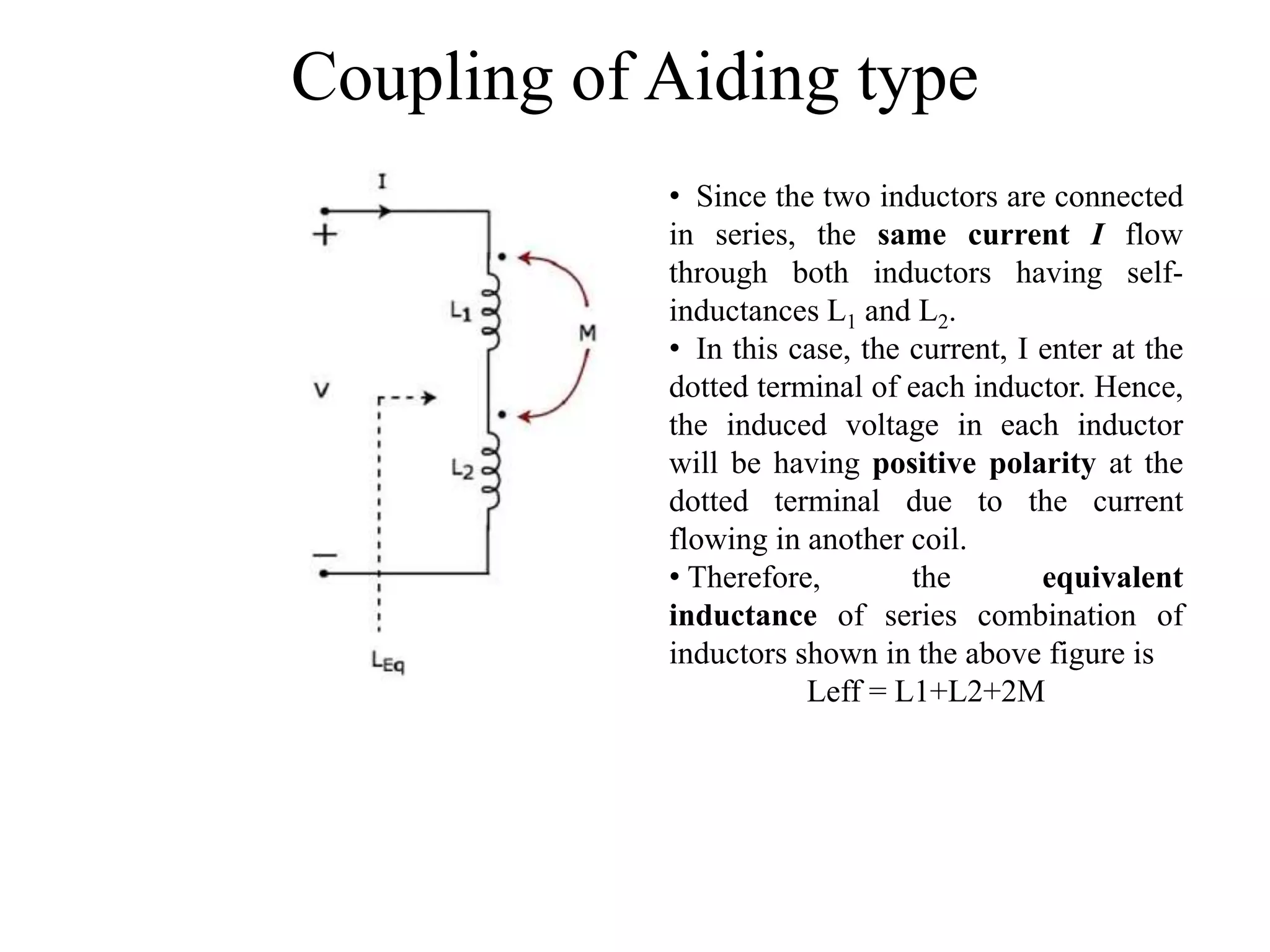
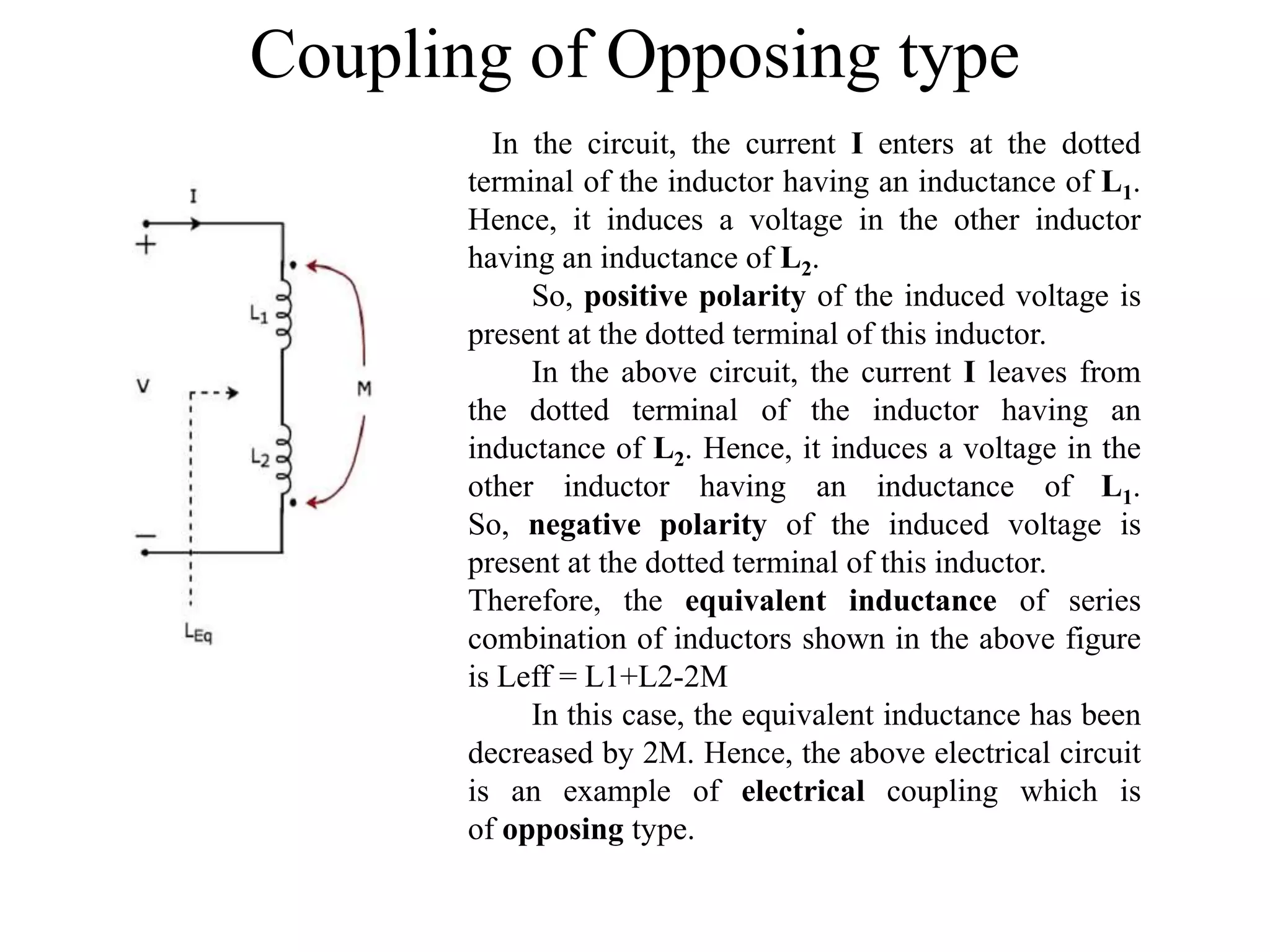
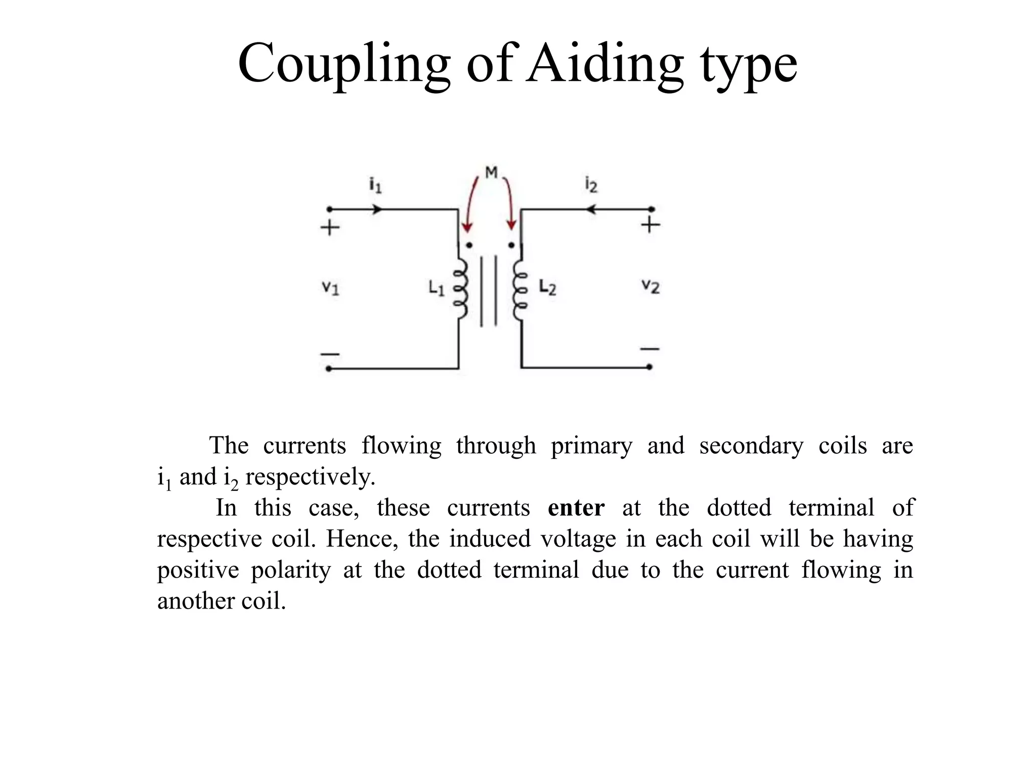
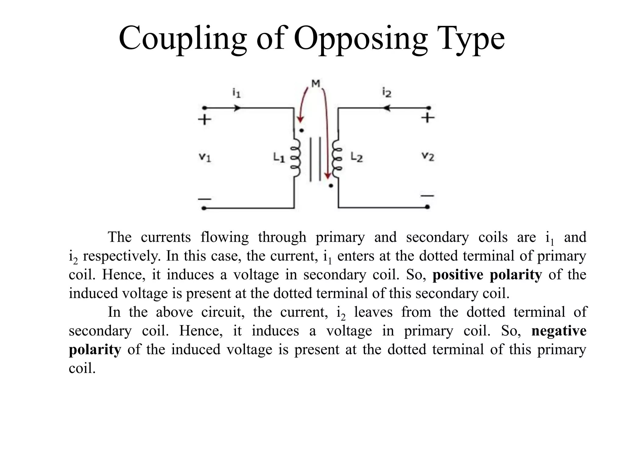
Dot Convention in Coupled
Circuits
T.Mrunalini
Coupled circuit
An electric circuit is said to be a coupled
circuit, when there exists a mutual inductance
between the coils (or inductors) present in that
circuit. In the absence of resistor, coil becomes
inductor. Sometimes, the terms coil and
inductor are interchangeably used.
Dot Convention
Dot convention is a technique, which gives
the details about voltage polarity at the dotted
terminal. This information is useful, while writing
KVL equations.
• If the current enters at the dotted terminal of one
coil (or inductor), then it induces a voltage at
another coil (or inductor), which is
having positive polarity at the dotted terminal.
• If the current leaves from the dotted terminal of
one coil (or inductor), then it induces a voltage at
another coil (or inductor), which is
having negative polarity at the dotted terminal.
Classification of Coupling
Coupling is classified into the following two
categories.
• Electrical Coupling
• Magnetic Coupling
Electrical Coupling
• Electrical coupling occurs, when there exists
a physical connection between two coils (or
inductors). This coupling can be of either
aiding type or opposing type. It is based on
whether the current enters at the dotted
terminal or leaves from the dotted terminal.
Coupling of Aiding type
• Since the two inductors are connected
in series, the same current I flow
through both inductors having self-
inductances L1 and L2.
• In this case, the current, I enter at the
dotted terminal of each inductor. Hence,
the induced voltage in each inductor
will be having positive polarity at the
dotted terminal due to the current
flowing in another coil.
• Therefore, the equivalent
inductance of series combination of
inductors shown in the above figure is
Leff = L1+L2+2M
Coupling of Opposing type
In the circuit, the current I enters at the dotted
terminal of the inductor having an inductance of L1.
Hence, it induces a voltage in the other inductor
having an inductance of L2.
So, positive polarity of the induced voltage is
present at the dotted terminal of this inductor.
In the above circuit, the current I leaves from
the dotted terminal of the inductor having an
inductance of L2. Hence, it induces a voltage in the
other inductor having an inductance of L1.
So, negative polarity of the induced voltage is
present at the dotted terminal of this inductor.
Therefore, the equivalent inductance of series
combination of inductors shown in the above figure
is Leff = L1+L2-2M
In this case, the equivalent inductance has been
decreased by 2M. Hence, the above electrical circuit
is an example of electrical coupling which is
of opposing type.
Magnetic Coupling
• Magnetic coupling occurs, when there is no
physical connection between two coils (or
inductors). This coupling can be of either
aiding type or opposing type. It is based on
whether the current enters at the dotted
terminal or leaves from the dotted terminal.
Coupling of Aiding type
The currents flowing through primary and secondary coils are
i1 and i2 respectively.
In this case, these currents enter at the dotted terminal of
respective coil. Hence, the induced voltage in each coil will be having
positive polarity at the dotted terminal due to the current flowing in
another coil.
Coupling of Opposing Type
The currents flowing through primary and secondary coils are i1 and
i2 respectively. In this case, the current, i1 enters at the dotted terminal of primary
coil. Hence, it induces a voltage in secondary coil. So, positive polarity of the
induced voltage is present at the dotted terminal of this secondary coil.
In the above circuit, the current, i2 leaves from the dotted terminal of
secondary coil. Hence, it induces a voltage in primary coil. So, negative
polarity of the induced voltage is present at the dotted terminal of this primary
coil.
Thank You

Dot convention in coupled circuits

  • 1.
    Dot Convention inCoupled Circuits T.Mrunalini
  • 2.
    Coupled circuit An electriccircuit is said to be a coupled circuit, when there exists a mutual inductance between the coils (or inductors) present in that circuit. In the absence of resistor, coil becomes inductor. Sometimes, the terms coil and inductor are interchangeably used.
  • 3.
    Dot Convention Dot conventionis a technique, which gives the details about voltage polarity at the dotted terminal. This information is useful, while writing KVL equations. • If the current enters at the dotted terminal of one coil (or inductor), then it induces a voltage at another coil (or inductor), which is having positive polarity at the dotted terminal. • If the current leaves from the dotted terminal of one coil (or inductor), then it induces a voltage at another coil (or inductor), which is having negative polarity at the dotted terminal.
  • 4.
    Classification of Coupling Couplingis classified into the following two categories. • Electrical Coupling • Magnetic Coupling
  • 5.
    Electrical Coupling • Electricalcoupling occurs, when there exists a physical connection between two coils (or inductors). This coupling can be of either aiding type or opposing type. It is based on whether the current enters at the dotted terminal or leaves from the dotted terminal.
  • 6.
    Coupling of Aidingtype • Since the two inductors are connected in series, the same current I flow through both inductors having self- inductances L1 and L2. • In this case, the current, I enter at the dotted terminal of each inductor. Hence, the induced voltage in each inductor will be having positive polarity at the dotted terminal due to the current flowing in another coil. • Therefore, the equivalent inductance of series combination of inductors shown in the above figure is Leff = L1+L2+2M
  • 7.
    Coupling of Opposingtype In the circuit, the current I enters at the dotted terminal of the inductor having an inductance of L1. Hence, it induces a voltage in the other inductor having an inductance of L2. So, positive polarity of the induced voltage is present at the dotted terminal of this inductor. In the above circuit, the current I leaves from the dotted terminal of the inductor having an inductance of L2. Hence, it induces a voltage in the other inductor having an inductance of L1. So, negative polarity of the induced voltage is present at the dotted terminal of this inductor. Therefore, the equivalent inductance of series combination of inductors shown in the above figure is Leff = L1+L2-2M In this case, the equivalent inductance has been decreased by 2M. Hence, the above electrical circuit is an example of electrical coupling which is of opposing type.
  • 8.
    Magnetic Coupling • Magneticcoupling occurs, when there is no physical connection between two coils (or inductors). This coupling can be of either aiding type or opposing type. It is based on whether the current enters at the dotted terminal or leaves from the dotted terminal.
  • 9.
    Coupling of Aidingtype The currents flowing through primary and secondary coils are i1 and i2 respectively. In this case, these currents enter at the dotted terminal of respective coil. Hence, the induced voltage in each coil will be having positive polarity at the dotted terminal due to the current flowing in another coil.
  • 10.
    Coupling of OpposingType The currents flowing through primary and secondary coils are i1 and i2 respectively. In this case, the current, i1 enters at the dotted terminal of primary coil. Hence, it induces a voltage in secondary coil. So, positive polarity of the induced voltage is present at the dotted terminal of this secondary coil. In the above circuit, the current, i2 leaves from the dotted terminal of secondary coil. Hence, it induces a voltage in primary coil. So, negative polarity of the induced voltage is present at the dotted terminal of this primary coil.
  • 11.