Model Outline KDSeries Engine Chassis Body Body Electrical
Contents
Click a Section Tab
2.
Model Outline KDSeries Engine Chassis Body Body Electrical
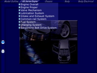
Engine Overall
Engine Proper
Valve Mechanism
Lubrication System
Intake and Exhaust System
Common-rail System
Fuel System
Charging System
Serpentine Belt Drive System
3.
Model Outline KDSeries Engine Chassis Body Body Electrical
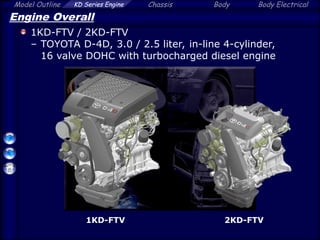
Engine Overall
1KD-FTV / 2KD-FTV
– TOYOTA D-4D, 3.0 / 2.5 liter, in-line 4-cylinder,
16 valve DOHC with turbocharged diesel engine
1KD-FTV 2KD-FTV
4.
Model Outline KDSeries Engine Chassis Body Body Electrical
Engine Overall
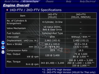
1KD-FTV / 2KD-FTV Specifications
Item
1KD-FTV
(HILUX)
2KD-FTV
(HILUX, INNOVA)
No. of Cylinders &
Arrangement
4-Cylinder, In-line
Valve Mechanism
16-Valve DOHC,
Belt & Gear Drive
Fuel System Common-Rail Type
Intercooler With Without / With *2
Displacement cm3 (cu. in.) 2,982 (182.0) 2,492 (152.2)
Bore x Stroke
mm (in.)
96.0 x 103.0
(3.78 x 4.06)
92.0 x 93.8
(3.62 x 3.69)
Compression Ratio 18.4 18.5
Max. Output
kW @ rpm
120 @ 3,400
75 @ 3,600
88 @ 3,600 *2
Max. Torque
N·m @ rpm
343 @1,400 ~ 3,200
200 @ 1,400 ~ 3,200
260 @ 1,600 ~ 2,400 *1
320 @ 2,000 *2
*1: 2KD-FTV High Version
*2: 2KD-FTV High Version (HILUX for Thai only)
5.
Model Outline KDSeries Engine Chassis Body Body Electrical
Engine Overall
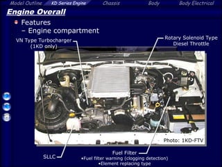
Features
– Engine compartment
Fuel Filter
•Fuel filter warning (clogging detection)
•Element replacing type
SLLC
Rotary Solenoid Type
Diesel Throttle
VN Type Turbocharger
(1KD only)
Photo: 1KD-FTV
6.
Model Outline KDSeries Engine Chassis Body Body Electrical
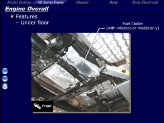
Engine Overall
Features
– Under floor Fuel Cooler
(with intercooler model only)
Front
7.
Model Outline KDSeries Engine Chassis Body Body Electrical
Engine Proper
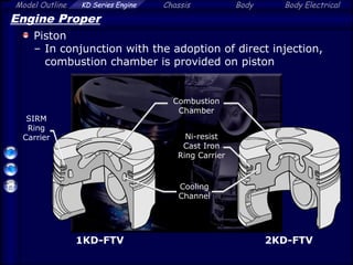
Piston
– In conjunction with the adoption of direct injection,
combustion chamber is provided on piston
Combustion
Chamber
Ni-resist
Cast Iron
Ring Carrier
Cooling
Channel
1KD-FTV 2KD-FTV
SIRM
Ring
Carrier
8.
Model Outline KDSeries Engine Chassis Body Body Electrical
Valve Mechanism
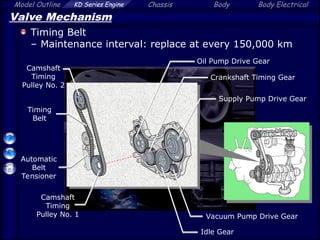
Timing Belt
– Maintenance interval: replace at every 150,000 km
Timing
Belt
Automatic
Belt
Tensioner
Camshaft
Timing
Pulley No. 2
Camshaft
Timing
Pulley No. 1
Oil Pump Drive Gear
Crankshaft Timing Gear
Supply Pump Drive Gear
Idle Gear
Vacuum Pump Drive Gear
9.
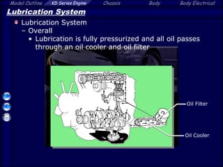
Model Outline KDSeries Engine Chassis Body Body Electrical
Lubrication System
Lubrication System
– Overall
• Lubrication is fully pressurized and all oil passes
through an oil cooler and oil filter
Oil Cooler
Oil Filter
10.
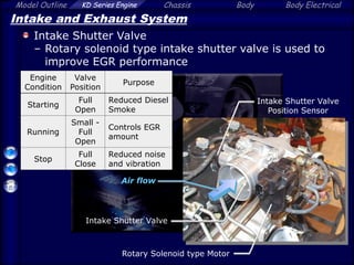
Model Outline KDSeries Engine Chassis Body Body Electrical
Intake and Exhaust System
Intake Shutter Valve
– Rotary solenoid type intake shutter valve is used to
improve EGR performance
Engine
Condition
Valve
Position
Purpose
Starting
Full
Open
Reduced Diesel
Smoke
Running
Small -
Full
Open
Controls EGR
amount
Stop
Full
Close
Reduced noise
and vibration
Rotary Solenoid type Motor
Intake Shutter Valve
Position Sensor
Intake Shutter Valve
Air flow
11.
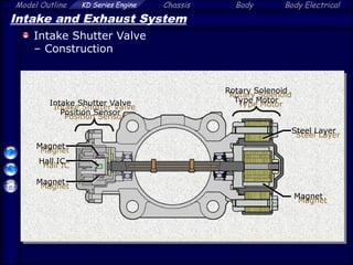
Model Outline KDSeries Engine Chassis Body Body Electrical
Intake and Exhaust System
Intake Shutter Valve
– Construction
Hall IC
Magnet
Magnet
Steel Layer
Magnet
Intake Shutter Valve
Position Sensor
Rotary Solenoid
Type Motor
12.
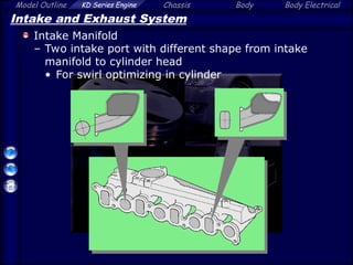
Model Outline KDSeries Engine Chassis Body Body Electrical
Intake and Exhaust System
Intake Manifold
– Two intake port with different shape from intake
manifold to cylinder head
• For swirl optimizing in cylinder
13.
Model Outline KDSeries Engine Chassis Body Body Electrical
Intake and Exhaust System
Swirl Control Valve (1KD only)
– Swirl control valve is provided to realize clean
emission
Swirl Control Valve
Intake Manifold
Actuator
VSV for SCV
1KD-FTV only
14.
Model Outline KDSeries Engine Chassis Body Body Electrical
At low engine speed,
SCV is closed to
strengthen the swirl
Intake and Exhaust System
Swirl Control Valve (1KD only)
– Operation
Actuator
Intake
Air
VSV
Vacuum
Pump
Engine
ECU
Accelerator
Pedal Opening
Engine Speed
ON / OFF
15.
Model Outline KDSeries Engine Chassis Body Body Electrical
Intake and Exhaust System
Variable Nozzle Vane Type Turbocharger (1KD only)
– Nozzle Vane is driven by DC motor
DC Motor
Link
Turbine
Wheel
Full-
Close
Stopper
Motor Rod
Nozzle Vane
Position Sensor
16.
Model Outline KDSeries Engine Chassis Body Body Electrical
Intake and Exhaust System
Variable Nozzle Vane Type Turbocharger (1KD only)
– Construction
DC Motor
Link
Nozzle Vane
Turbine
Wheel
Motor Rod
Nozzle Vane
Position Sensor
Full-
Close
Stopper
Intake Air
Reduction
Gears
Exhaust
Gas
17.
Model Outline KDSeries Engine Chassis Body Body Electrical
Intake and Exhaust System
Variable Nozzle Vane Type Turbocharger (1KD only)
– Construction
Drive Arm
Unison Ring
Driven Arm
Turbine
Wheel
Full-Close Stopper
Link
Motor Rod
Nozzle
Vane
Gas Flow
18.
Model Outline KDSeries Engine Chassis Body Body Electrical
Intake and Exhaust System
Variable Nozzle Vane Type Turbocharger (1KD only)
– Feedback Control
Nozzle
Vane
Position
Turbo Motor
Driver
Target Angle
Control Status
Engine
ECU
Turbo Pressure
Sensor
Atmospheric
Temp. Sensor
Atmospheric
Pressure
Sensor
Water Temp.
Sensor
Injector (EDU)
Crankshaft
Position Sensor
DC
Motor
Nozzle
Vane
Position
Sensor
Control
19.
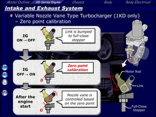
Model Outline KDSeries Engine Chassis Body Body Electrical
Intake and Exhaust System
Variable Nozzle Vane Type Turbocharger (1KD only)
– Zero point calibration
IG
OFF ON
IG
ON OFF
After the
engine
start
Close
Open
Motor Rod
Full-Close
Stopper
0
Link
0
Link is bumped
to full-close
stopper
Zero point
calibration
Nozzle vane is
controlled based
on the zero point
20.
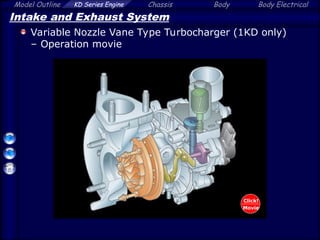
Model Outline KDSeries Engine Chassis Body Body Electrical
Intake and Exhaust System
Variable Nozzle Vane Type Turbocharger (1KD only)
– Operation movie
Click!
Movie
21.
Model Outline KDSeries Engine Chassis Body Body Electrical
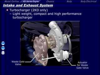
Intake and Exhaust System
Turbocharger (2KD only)
– Light weight, compact and high performance
turbocharger
Waste Gate
Valve
Actuator
for Waste
Gate Valve
22.
Model Outline KDSeries Engine Chassis Body Body Electrical
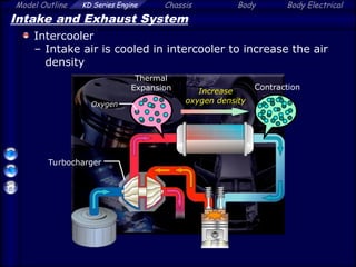
Intake and Exhaust System
Intercooler
– Intake air is cooled in intercooler to increase the air
density
Turbocharger
Thermal
Expansion Contraction
Increase
oxygen density
Oxygen
23.
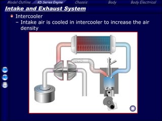
Model Outline KDSeries Engine Chassis Body Body Electrical
Intake and Exhaust System
Intercooler
– Intake air is cooled in intercooler to increase the air
density
24.
Model Outline KDSeries Engine Chassis Body Body Electrical
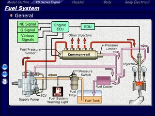
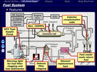
Fuel System
General
Fuel Pressure
Sensor
EDU
Pressure
Limiter
Supply Pump
SCV
Engine
ECU
Fuel Tank
Injector
NE Signal
G Signal
Various
Signals
Common-rail
Fuel Cooler
Pressure
Switch
Fuel
Filter
Fuel System
Warning Light
Other Injectors
25.
Model Outline KDSeries Engine Chassis Body Body Electrical
Fuel System
Features
Fuel Pressure
Sensor
EDU
Pressure
Limiter
Supply Pump
SCV
Engine
ECU
Fuel Tank
Injector
NE Signal
G Signal
Various
Signals
Common-rail
Fuel Cooler
Pressure
Switch
Fuel
Filter
Fuel System
Warning Light
Other Injectors
Max. 160MPa
HP3 Type
Supply
Pump
Warning light
for fuel filter
clogging and
fuel sedimenter
Injector
compensation
code
Element
replacement
type
Detects
filter
clogging
Fuel cooler
cools return
fuel
26.
Model Outline KDSeries Engine Chassis Body Body Electrical
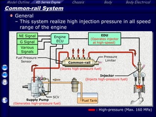
Common-rail System
General
– This system realize high injection pressure in all speed
range of the engine
Fuel Pressure
Sensor
Pressure
Limiter
Engine
ECU
Fuel Tank
NE Signal
G Signal
Various
Signals
SCV
Supply Pump
(Generates high-pressure fuel)
Common-rail
Injector
(Injects high-pressure fuel)
EDU
(Operates injector
at high-speed)
: High-pressure (Max. 160 MPa)
(Stores high-pressure fuel)
27.
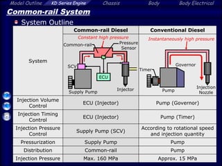
Model Outline KDSeries Engine Chassis Body Body Electrical
Common-rail System
System Outline
System
Common-rail Diesel Conventional Diesel
Injection Volume
Control
ECU (Injector) Pump (Governor)
Injection Timing
Control
ECU (Injector) Pump (Timer)
Injection Pressure
Control
Supply Pump (SCV)
According to rotational speed
and injection quantity
Pressurization Supply Pump Pump
Distribution Common-rail Pump
Injection Pressure Max. 160 MPa Approx. 15 MPa
Pressure
Sensor
Constant high pressure
ECU
SCV
Supply Pump
Common-rail
Injector
Instantaneously high pressure
Timer
Governor
Pump
Injection
Nozzle
28.
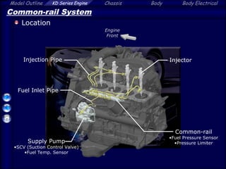
Model Outline KDSeries Engine Chassis Body Body Electrical
Common-rail System
Location
Common-rail
•Fuel Pressure Sensor
•Pressure Limiter
Supply Pump
•SCV (Suction Control Valve)
•Fuel Temp. Sensor
Injector
Engine
Front
Injection Pipe
Fuel Inlet Pipe
29.
Model Outline KDSeries Engine Chassis Body Body Electrical
Common-rail System
Supply Pump
– Supplies the high pressure fuel to the common-rail
– Driven by crankshaft
From Fuel Filter
(Inlet)
To Common-rail
(Outlet)
To Fuel Tank
(Return)
SCV
(Suction Control Valve)
30.
Model Outline KDSeries Engine Chassis Body Body Electrical
Common-rail System
Supply Pump
– Construction
Plunger
Feed
Pump
Delivery
Valve
SCV (Suction
Control Valve)
Fuel
Temp.
Sensor
Check
Valve
Eccentric and
Ring Cam
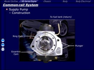
31.
Model Outline KDSeries Engine Chassis Body Body Electrical
Common-rail System
Supply Pump
– Construction
Ring Cam
Plunger
Eccentric
Cam
To fuel tank (return)
32.
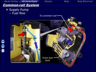
Model Outline KDSeries Engine Chassis Body Body Electrical
Common-rail System
Supply Pump
– Fuel flow
From fuel
tank
To common-rail
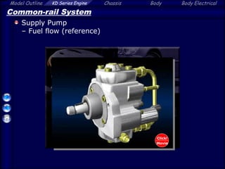
33.
Model Outline KDSeries Engine Chassis Body Body Electrical
Common-rail System
Supply Pump
– Fuel flow (reference)
Click!
Movie
34.
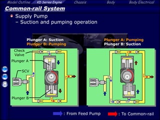
Model Outline KDSeries Engine Chassis Body Body Electrical
Common-rail System
Supply Pump
– Suction and pumping operation
SCV
: From Feed Pump : To Common-rail
Plunger A: Suction
Plunger B: Pumping
Plunger A: Pumping
Plunger B: Suction
Plunger A
Plunger B
Check
Valve
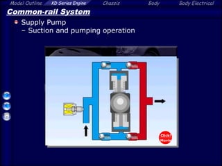
35.
Model Outline KDSeries Engine Chassis Body Body Electrical
Common-rail System
Supply Pump
– Suction and pumping operation
Click!
Movie
36.
Model Outline KDSeries Engine Chassis Body Body Electrical
Common-rail System
Supply Pump
– Fuel control operation (SCV opening small)
Fuel
Pumping
Mass
37.
Model Outline KDSeries Engine Chassis Body Body Electrical
Common-rail System
Supply Pump
– Fuel control operation (SCV opening large)
Fuel
Pumping
Mass
38.
Model Outline KDSeries Engine Chassis Body Body Electrical
Common-rail System
Supply Pump
– Fuel control operation (SCV opening small)
Click!
Movie
39.
Model Outline KDSeries Engine Chassis Body Body Electrical
Common-rail System
Supply Pump
– Fuel control operation (SCV opening large)
Click!
Movie
40.
Model Outline KDSeries Engine Chassis Body Body Electrical
Common-rail System
Supply Pump
– The SCV opening regulates the pumping volume to
control fuel pressure
Controls
SCV
opening
Common-rail
pressure
(Feedback)
Accelerator Pedal
Position Sensor
SCV
Fuel Pressure
Sensor
Crankshaft
Position Sensor
Engine ECU
Calculation of
target injection
pressure
[Fuel Pressure Control]
41.
Model Outline KDSeries Engine Chassis Body Body Electrical
Common-rail System
Common-rail
– Stores high-pressure fuel (Max. 160 MPa) produced by
supply pump
From
Supply Pump
To Injector To Fuel Tank
Fuel
Pressure
Sensor
Pressure
Limiter
Common-rail
42.
Model Outline KDSeries Engine Chassis Body Body Electrical
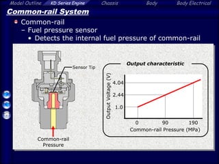
Common-rail System
Common-rail
– Fuel pressure sensor
• Detects the internal fuel pressure of common-rail
Common-rail
Pressure
0 190
1.0
4.04
Common-rail Pressure (MPa)
Output
Voltage
(V)
Output characteristic
Sensor Tip
90
2.44
43.
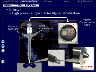
Model Outline KDSeries Engine Chassis Body Body Electrical
Common-rail System
Injector
– High pressure injection for higher atomization
Injector
Compensation
Code
From
Common-rail
Return to
Fuel Tank
0.14 mm
44.
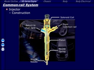
Model Outline KDSeries Engine Chassis Body Body Electrical
Common-rail System
Injector
– Construction
Nozzle
Needle
Piston
Solenoid Coil
Return to
Fuel Tank
From
Common-rail
Nozzle
Spring
45.
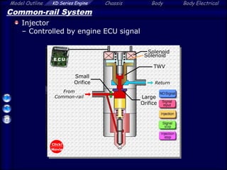
Model Outline KDSeries Engine Chassis Body Body Electrical
Common-rail System
Injector
– Controlled by engine ECU signal
Solenoid
Solenoid
TWV
Return
From
Common-rail Large
Orifice
Small
Orifice
Click!
Movie
46.
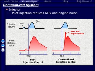
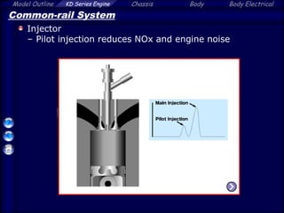
Model Outline KDSeries Engine Chassis Body Body Electrical
Common-rail System
Injector
– Pilot injection reduces NOx and engine noise
TDC
TDC
Pilot
Injection Control
Conventional
Injection Control
Pilot
Main
Heat
Release
Value
Injection
Volume
NOx and
engine noise
47.
Model Outline KDSeries Engine Chassis Body Body Electrical
Common-rail System
Injector
– Pilot injection reduces NOx and engine noise
48.
Model Outline KDSeries Engine Chassis Body Body Electrical
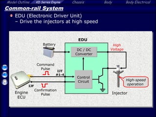
Common-rail System
EDU (Electronic Driver Unit)
– Drive the injectors at high speed
Engine
ECU
EDU
Injector
High
Voltage
DC / DC
Converter
Command
Pulse
Confirmation
Pulse
Battery
IJT
#1-4
IJF
Control
Circuit High-speed
operation
49.
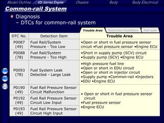
Model Outline KDSeries Engine Chassis Body Body Electrical
Fail-safe
Detection Condition
Common-rail System
Diagnosis
– DTCs for common-rail system
DTC No. Detection Item Trouble Area
P0087
(49)
Fuel Rail/System
Pressure - Too Low
•Open or short in fuel pressure sensor
circuit •Fuel pressure sensor •Engine ECU
P0088
(78)
Fuel Rail/System
Pressure - Too High
•Short in supply pump (SCV) circuit
•Supply pump (SCV) •Engine ECU
P0093
(78)
Fuel System Leak
Detected - Large Leak
•High pressure fuel line
•Open or short in EDU circuit
•Open or short in injector circuit
•Supply pump •Common-rail •Injectors
•EDU •Engine ECU
P0190
(49)
Fuel Rail Pressure Sensor
Circuit Malfunction
• Open or short in fuel pressure sensor
circuit
•Fuel pressure sensor
•Engine ECU
P0192
(49)
Fuel Rail Pressure Sensor
Circuit Low Input
P0193
(49)
Fuel Rail Pressure Sensor
Circuit High Input
Trouble Area
50.
Model Outline KDSeries Engine Chassis Body Body Electrical
Common-rail System
Diagnosis
– DTCs for common-rail system
DTC No. Detection Item Detection Condition
P0087
(49)
Fuel Rail/System
Pressure - Too Low
Fuel pressure sensor output voltage stays
at fixed value
P0088
(78)
Fuel Rail/System
Pressure - Too High
Fuel pressure exceeds predetermined
value
P0093
(78)
Fuel System Leak
Detected - Large Leak
Difference of common-rail pressure before
and after fuel injection varies greatly from
difference of value that engine ECU
calculates before and after injection
P0190
(49)
Fuel Rail Pressure Sensor
Circuit Malfunction
Fuel pressure sensor output voltage is
0.55V or less, or 4.9V or more for 0.5 sec.
P0192
(49)
Fuel Rail Pressure Sensor
Circuit Low Input
Fuel pressure sensor output voltage is
0.55V or less for 0.5 sec.
P0193
(49)
Fuel Rail Pressure Sensor
Circuit High Input
Fuel pressure sensor output voltage is
4.9V or more for 0.5 sec.
1 trip detection logic for all DTC
Detection Condition Fail-safe
Trouble Area
51.
Model Outline KDSeries Engine Chassis Body Body Electrical
Common-rail System
Diagnosis
– DTCs for common-rail system
DTC No. Detection Item Fail-safe
P0087
(49)
Fuel Rail/System
Pressure - Too Low
Limits engine power
P0088
(78)
Fuel Rail/System
Pressure - Too High
P0093
(78)
Fuel System Leak
Detected - Large Leak
Limits engine power for 1 min., and then
stops the engine
P0190
(49)
Fuel Rail Pressure Sensor
Circuit Malfunction
Limits engine power
P0192
(49)
Fuel Rail Pressure Sensor
Circuit Low Input
P0193
(49)
Fuel Rail Pressure Sensor
Circuit High Input
Trouble Area Fail-safe
Detection Condition
52.
Model Outline KDSeries Engine Chassis Body Body Electrical
Common-rail System
Diagnosis
– DTCs for common-rail system
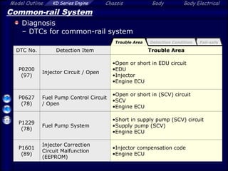
DTC No. Detection Item Trouble Area
P0200
(97)
Injector Circuit / Open
•Open or short in EDU circuit
•EDU
•Injector
•Engine ECU
P0627
(78)
Fuel Pump Control Circuit
/ Open
•Open or short in (SCV) circuit
•SCV
•Engine ECU
P1229
(78)
Fuel Pump System
•Short in supply pump (SCV) circuit
•Supply pump (SCV)
•Engine ECU
P1601
(89)
Injector Correction
Circuit Malfunction
(EEPROM)
•Injector compensation code
•Engine ECU
Fail-safe
Trouble Area Detection Condition
53.
Model Outline KDSeries Engine Chassis Body Body Electrical
Common-rail System
Diagnosis
– DTCs for common-rail system
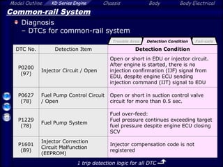
DTC No. Detection Item Detection Condition
P0200
(97)
Injector Circuit / Open
Open or short in EDU or injector circuit.
After engine is started, there is no
injection confirmation (IJF) signal from
EDU, despite engine ECU sending
injection command (IJT) signal to EDU
P0627
(78)
Fuel Pump Control Circuit
/ Open
Open or short in suction control valve
circuit for more than 0.5 sec.
P1229
(78)
Fuel Pump System
Fuel over-feed:
Fuel pressure continues exceeding target
fuel pressure despite engine ECU closing
SCV
P1601
(89)
Injector Correction
Circuit Malfunction
(EEPROM)
Injector compensation code is not
registered
1 trip detection logic for all DTC
Detection Condition
Trouble Area Fail-safe
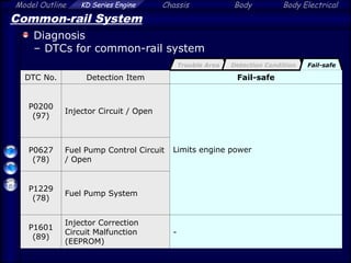
54.
Model Outline KDSeries Engine Chassis Body Body Electrical
Common-rail System
Diagnosis
– DTCs for common-rail system
DTC No. Detection Item Fail-safe
P0200
(97)
Injector Circuit / Open
Limits engine power
P0627
(78)
Fuel Pump Control Circuit
/ Open
P1229
(78)
Fuel Pump System
P1601
(89)
Injector Correction
Circuit Malfunction
(EEPROM)
-
Fail-safe
Detection Condition
Trouble Area
55.
Model Outline KDSeries Engine Chassis Body Body Electrical
Common-rail System
Service Point for Common-rail System
– Supply pump initialization and calibration
– Common-rail replacement
– Reprogramming of injector compensation code
– Replace a new parts
– Replace a new pipe
– Check fuel leak (Leakage Pipe No.1 / Fuel System)
– Power Balance Check
56.
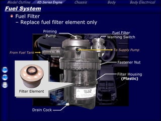
Model Outline KDSeries Engine Chassis Body Body Electrical
Fuel System
Fuel Filter
– Replace fuel filter element only
Fuel Filter
Warning Switch
From Fuel Tank
To Supply Pump
Priming
Pump
Filter Housing
(Plastic)
Fastener Nut
Drain Cock
Filter Element
57.
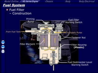
Model Outline KDSeries Engine Chassis Body Body Electrical
Fuel System
Fuel Filter
– Construction
Filter Element
Fuel Filter
Warning Switch
From Fuel Tank To Supply Pump
Priming
Pump
Fuel Sedimenter Level
Warning Switch
Filter Housing
(Plastic)
Fastener Nut
58.
Model Outline KDSeries Engine Chassis Body Body Electrical
Fuel System
Fuel Warning System
– Fuel filter clogging is detected by fuel filter warning
switch
Combination Meter
Fuel Filter
Warning Switch Fuel System
Warning Light
Fuel Filter
- Fuel Filter Maintenance Interval -
Fuel system warning light has been illuminated
Cloggin
g
59.
Model Outline KDSeries Engine Chassis Body Body Electrical
Fuel System
Fuel Warning System
– System Diagram
Combination Meter
Fuel Filter
Warning Switch
Meter
ECU
Filter Element
Fuel System
Warning Light
To Supply Pump
Vehicle Speed
Sensor
Fuel Sedimenter Level Warning Switch
Fuel Filter
60.
Model Outline KDSeries Engine Chassis Body Body Electrical
Fuel System
Fuel Warning System
– Fuel filter warning switch turns OFF when the filter
outlet pressure decreases
Fuel Filter
Warning
Switch
To Supply Pump
Filter Element
Normal Fuel Filter
(Switch: ON)
Fuel Filter Clogged Up
(Switch: OFF)
Diaphragm
ON Meter
ECU
Fuel Filter
Warning
Switch
To Supply Pump
OFF Meter
ECU
Negative
Pressure
61.
Model Outline KDSeries Engine Chassis Body Body Electrical
Fuel System
Fuel Warning System
– Warning light condition for fuel filter / fuel sedimenter
Warning
Warning
Method
Priority
Sedimenter
Warning
Blink
1
Fuel Filter
Warning
ON
2
62.
Model Outline KDSeries Engine Chassis Body Body Electrical
Fuel System
Fuel Warning System
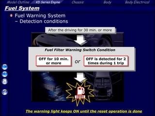
– Detection conditions
OFF for 10 min.
or more
OFF is detected for 2
times during 1 trip
After the driving for 30 min. or more
The warning light keeps ON until the reset operation is done
Fuel Filter Warning Switch Condition
or
63.
Model Outline KDSeries Engine Chassis Body Body Electrical
Charging System
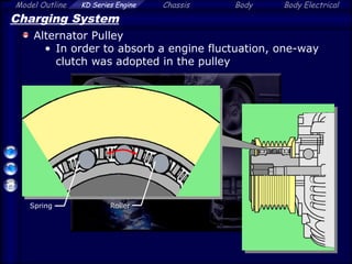
Alternator Pulley
• In order to absorb a engine fluctuation, one-way
clutch was adopted in the pulley
Roller
Spring
64.
Model Outline KDSeries Engine Chassis Body Body Electrical
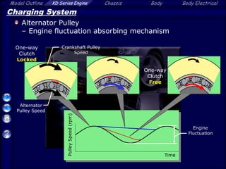
Charging System
Alternator Pulley
– Engine fluctuation absorbing mechanism
Engine
Fluctuation
Alternator
Pulley Speed
Crankshaft Pulley
Speed
Pulley
Speed
(rpm)
Time
One-way
Clutch
Locked
One-way
Clutch
Free
65.
Model Outline KDSeries Engine Chassis Body Body Electrical
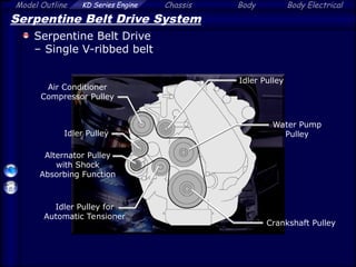
Serpentine Belt Drive System
Serpentine Belt Drive
– Single V-ribbed belt
Alternator Pulley
with Shock
Absorbing Function
Water Pump
Pulley
Air Conditioner
Compressor Pulley
Idler Pulley for
Automatic Tensioner
Idler Pulley
Idler Pulley
Crankshaft Pulley
Model Outline KDSeries Engine Chassis Body Body Electrical
Reference
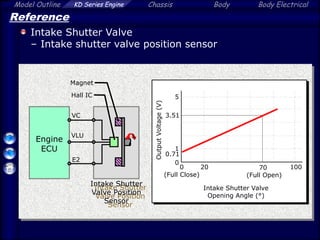
Intake Shutter Valve
– Intake shutter valve position sensor
Intake Shutter Valve
Opening Angle (°)
Output
Voltage
(V)
0
Engine
ECU
VC
VLU
Hall IC
Magnet
E2
0
(Full Close)
70
(Full Open)
Intake Shutter
Valve Position
Sensor
1
5
0.71
20 100
3.51
68.
Model Outline KDSeries Engine Chassis Body Body Electrical
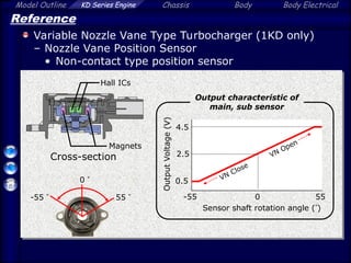
Reference
Variable Nozzle Vane Type Turbocharger (1KD only)
– Nozzle Vane Position Sensor
• Non-contact type position sensor
0
-55 55
0.5
2.5
4.5
Sensor shaft rotation angle ()
Output
Voltage
(V)
Output characteristic of
main, sub sensor
VN Close
VN Open
-55 55
Hall ICs
Magnets
Cross-section
0
69.
Model Outline KDSeries Engine Chassis Body Body Electrical
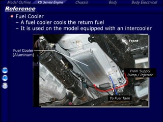
Reference
Fuel Cooler
– A fuel cooler cools the return fuel
– It is used on the model equipped with an intercooler
From Supply
Pump / Injector
To Fuel Tank
Fuel Cooler
(Aluminum)
Front
70.
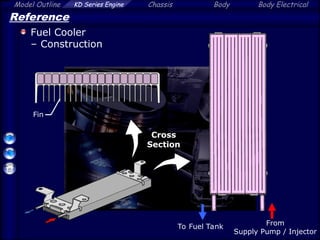
Model Outline KDSeries Engine Chassis Body Body Electrical
Reference
Fuel Cooler
– Construction
From
Supply Pump / Injector
To Fuel Tank
Cross
Section
Fin
71.
Model Outline KDSeries Engine Chassis Body Body Electrical
Reference
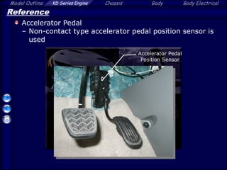
Accelerator Pedal
– Non-contact type accelerator pedal position sensor is
used
Accelerator Pedal
Position Sensor
72.
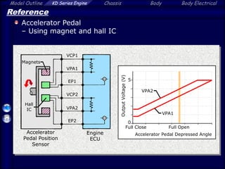
Model Outline KDSeries Engine Chassis Body Body Electrical
Reference
Accelerator Pedal
– Using magnet and hall IC
Accelerator Pedal Depressed Angle
Full Open
Full Close
VPA1
VPA2
Output
Voltage
(V) 0
5
VCP1
VCP2
VPA2
VPA1
Hall
IC
Magnets
EP1
EP2
Engine
ECU
Accelerator
Pedal Position
Sensor
Editor's Notes
#3 TOYOTA D-4D (Direct injection 4-stroke common-rail Diesel engine)
#4 Intercooler has been adopted on 1KD-FTV engine and it realizes higher output and torque
Each of the 2KD-FTV engine and the 2KD-FTV engine (High Version) is controlled by the different programmed engine ECU to tune their output and torque
#5 SLLC Maintenance Interval
- Inspect at every 40,000km
First replace at 160,000km, then replace at every 80,000km
Rotary solenoid type D-throttle
VN(Variable Nozzle vane) type turbocharger
Fuel filter
-Filter warning for maintenance
-Element replacing type
#6 A fuel cooler cools the return fuel
It is adopted only for models with intercooler
Injection pressure:
With intercooler model Max. 160 MPa
Without intercooler model Max. 135 MPa
#7 To improve the wear resistance of the top ring groove, the 1KD-FTV engine has adopted an SIRM (Sintered Iron Reinforced Metal) ring carrier and the 2KD-FTV engine has adopted an Ni-resist cast iron ring carrier
#8 Maintenance interval: replace at every 150,000 km
#10 -Rotary solenoid realizes linear control D-throttle
-At the engine starting: full open
-At the engine stop: full close
-During the engine operation: Linear control between small and full open to ensure driving condition and EGR performance to make vacuum in intake manifold
#11 A quick response and high precise control are realized by driving a valve shaft directly
Full Open Full Close: 100 ms
#12 Two different shape of intake port in each cylinder to make optimized swirl in cylinder
#13 -1KD-FTV engine equips swirl control valve in one of the intake ports in each cylinder
-This system makes strong swirl in cylinder to promotes air-fuel mixture for better combustion
#14 -The Valve is controlled by the engine ECU through VSV
-Operating condition of the valve
Low engine speed: close to strengthen the swirl in the combustion chamber
High engine speed: open
Cold engine start: open to reduce the white smoke
#15 -Variable nozzle vane type turbocharger(1KD-FTV only) to ensure higher effectiveness in full range
-Water-cooled type
#16 The system is controlled by engine ECU and nozzle vane is regulated by DC motor
#17 Depending on the engine speed, angle of vane is changed
At low engine speed, vane is turned and exhaust gas is effectively applied to turbine
#18 Engine ECU always detects and controls the vane optimally
#19 -The motor rod position is calibrated as zero point when IG is turned
-Nozzle vane is controlled based on the sensor zero point
-Don’t tighten or loosen the Full-Close Stopper lock nut
#20 Don’t tighten or loosen the full-close stopper lock nut
After the replacement or reinstallation of the turbocharger, perform the operation check before engine starting
#23 After turbocharger, heated intake air is cooled down to increase the air density. Thus, engine outputs higher power and torque
#24 After turbocharger, heated intake air is cooled down to increase the air density. Thus, engine outputs higher power and torque
#25 Common-rail Diesel system
-Higher output
-Low noise and vibration
-Cleaner emission
#26 Features
-Two opposed type (HP3) supply pump
-Higher pressure fuel (160 MPa)
-QR type Injector compensation
-Fuel filter warning system with segimenter
-Fuel filter element replacement
-Fuel cooler
#38 SCV adjusts fuel volume supplied to common rail and regulates internal fuel pressure
#39 SCV adjusts fuel volume supplied to common rail and regulates internal fuel pressure
#43 Engine ECU calculates the target injection pressure (Max. 160 MPa) based on the signals from the acceleration pedal position sensor and the crankshaft position sensor (Driving condition)
Engine ECU controls the SCV opening to regulate the pumping volume, so that the pressure detected by the fuel pressure sensor matches the target injection pressure
- Common-rail Pressure (Target Injection Pressure) -
1KD, 2KD with Intercooler: 30 – 160 MPa (306 – 1632 kgf/cm2, 4351 – 23206 psi)
2KD without Intercooler: 30 – 135 MPa (306 – 1377 kgf/cm2, 4351 – 19580 psi)
#44 Pressure Limiter: Relief the fuel when pressure rises abnormally high (200 MPa)
Discharge valve is discontinued from previous 2KD-FTV
#46 Small injection hole (0.14 mm)
1KD-FTV: 8-hole type
2KD-FTV: 6-hole type
#49 No Injection
-Solenoid is not energized and the TWV is closed by spring and fuel pressure. Nozzle also closes by high pressure fuel in chamber
Injection Start
-Solenoid operates to open TWV. Then, fuel starts to flow out of the control chamber through large orifice.
-Nozzle needle rises and injection starts.
-The orifice also causes the injection rate to increase gradually.
Injection End
-Solenoid is finished to energized and TWV is closed by the valve spring and fuel pressure.
-High-pressure fuel is applied in chamber
-Nozzle is closed rapidly, and sharp injection end is realized.
#50 Pilot injection
-Inject small amount of fuel initially before main injection timing
-It shortens ignition delay at the main injection
-It reduces noise, vibration and emission by preventing sudden rising of combustion pressure in cylinder
#51 Pilot injection
-Inject small amount of fuel initially before main injection timing
-It shortens ignition delay at the main injection
-It reduces noise, vibration and emission by preventing sudden rising of combustion pressure in cylinder
#52 -EDU converts to high voltage signal by receiving the injection signal from engine ECU to realizes high response operation.
-EDU outputs confirmation signal (IJF) to engine ECU to detect operation condition
#60 -Initialization and calibration are required after replacement of pump or engine ECU.
-Engine ECU learns and memorizes the pump discharge volume variances
#61 Initialization:
1, Short the TC and CG terminals of DLC3
2, IG ON
3, Wait for 3 min.
4, IG OFF
Calibration: (With Intelligent Tester II)
1, Start and warm-up the engine (until the engine coolant temp.[THW] more than 60 °C and fuel temp.[THF] more than 20°C)
2, Idling for 1 min. after the warm-up
3, IG OFF
(THW > 60°C Thermostat open)
(THF > 20°C with IT II)
#62 NOTE: If disassembled, change common-rail assembly
#63 -Injector replacement: New injector’s compensation value should be reprogrammed in engine ECU
-Engine ECU is changed: All of the existing injector compensation codes must be input to new engine ECU.
#64 After replacement of engine ECU or injector, DTC P1601 is set
#65 NOTE: Before replacement of engine ECU, injector compensation code for all injectors should be saved in the Intelligent Tester II
#78 After replacement, reprogram injector compensation code which are saved
#97 Without Intelligent Tester II [ Perform Fuel Leak Teat (Active Test) ]
-Fully depress the accelerator pedal quickly
-Make maximum engine speed and keep it for 2 sec.
-Repeat this operation several times
#98 CAUTION: Do not disconnect the injector connector while engine running because of high voltage
#99 Fuel filter type is changed from cartridge type to element only
#100 Fuel filter warning is added.
Basic construction is same as previous diesel engine system.
-Sedimenter level warning system
-Priming pump
#101 Fuel filter maintenance timing:
Fuel system warning light in combination meter turns on when filter replacement is required.
***This warning light is for both filter warning and sedimenter warning
#102 Fuel filter warning: filter clogging detection
Sedimenter warning: water level detection by float system
#103 -Fuel filter clogging system: Vacuum type sensor
-Filter element is clogged, suction from supply pump generates higher negative pressure in fuel pipe. Then, switch is turned off.
#104 Warning condition:
-Sedimenter warning: blink
-Fuel filter warning: stays on
If the both sedimenter and fuel filter warning are detected, the warning light blinks (as sedimenter warning)
#105 Fuel Filter Warning Detection Conditions
- Fuel filter warning switch is OFF for 10 min. or more
- Fuel filter warning switch OFF is detected for 2 times during 1 trip (OFF for 1 sec. or more = 1 time)
#106 Fuel Filter Maintenance
Change fuel filter element
#107 Removal:
1, Disconnect battery negative terminal
2, Loosen the fuel cap (reduce tank pressure)
3, Disconnect the fuel filter warning switch connector
4, Disconnect the hose connected to the filter inlet side
5, Connect the hose to drain cock and drain fuel inside (approx. 50 cc)
#108 6, Loosen the fastener nut using screwdriver, and fully loosen by hand
#109 7, Remove the filter cap
8, Remove the filter element from the case
9, Remove O-ring
Installation:
1, Attach 3 new O-rings to new element and the case
#110 2, Install new filter element and cover the filter cap to the case
NOTE: Align match mark
3, Tighten the fastener nut
NOTE: Tighten the nut until match mark is aligned
#111 4, Connect the hose to the filter inlet side
5, Tighten the fuel cap
6, Connect battery negative terminal
***NOT connect the fuel filter warning switch connector
#112 Reset Operation:
IG ON (The fuel filter warning switch connector should be disconnected before IG ON)
Connect the fuel filter warning switch connector 3 – 60 sec. after IG ON
3 sec. after the step2, fuel system warning light is turned OFF (Completion of the reset)
#113 After replacement of the filter, bleed the air in fuel system by priming pump
#114 A compact and lightweight segment conductor type alternator (SE08 type)
#120 Sensor uses hall IC as no contact type to ensure its durability and reliability
#121 Vane angle is detected by its position sensor with hall IC as non contact type
#122 Fuel cooler cools the return fuel from engine
Fuel cooler with intercooler model only

![Model Outline KD Series Engine Chassis Body Body Electrical
Common-rail System
Supply Pump
– The SCV opening regulates the pumping volume to
control fuel pressure
Controls
SCV
opening
Common-rail
pressure
(Feedback)
Accelerator Pedal
Position Sensor
SCV
Fuel Pressure
Sensor
Crankshaft
Position Sensor
Engine ECU
Calculation of
target injection
pressure
[Fuel Pressure Control]](https://image.slidesharecdn.com/dokumen-250423164523-3dee90a2/85/dokumen-tips_engine-1kd-2kd_D4D_exploded_view-ppt-40-320.jpg)
![Land cruiser (engine_[1_vd-ftv]) (2)](https://cdn.slidesharecdn.com/ss_thumbnails/landcruiserengine1vd-ftv2-150603112342-lva1-app6891-thumbnail.jpg?width=640&height=640&fit=bounds)


![[Volkswagen] manual de_taller_volkswagen_lupo](https://cdn.slidesharecdn.com/ss_thumbnails/volkswagenmanualdetallervolkswagenlupo-191021180259-thumbnail.jpg?width=640&height=640&fit=bounds)


