Download as PDF, PPTX

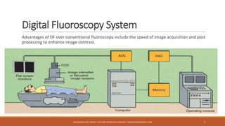


The document discusses digital fluoroscopy (DF) and its advantages over conventional fluoroscopy, including faster image acquisition and enhanced contrast. It explains the technology behind DF, including the use of charge-coupled devices (CCDs) and flat panel image receptors (FPIRs), which improve sensitivity and reduce radiation dose. The document also covers the process of digital subtraction angiography (DSA) and methods for image subtraction to visualize vascular structures.


![ONFH[AVN HIP] -TRIPLE REGIME -A NOVAL SURGICAL CONCEPT .pptx](https://cdn.slidesharecdn.com/ss_thumbnails/onfhavnhip2026koaconcalicutdrgokuldevdrmashraf-260210064517-213ec005-thumbnail.jpg?width=640&height=640&fit=bounds)
![CTEV [ clubfoot] DR ARUN LAL ,DR MOHAMED ASHRAF travancore medical college k...](https://cdn.slidesharecdn.com/ss_thumbnails/ctevclubfootdrarunlaldrmohamedashraftravancoremedicalcollegekollamkeralaindia-260208063247-18fc466c-thumbnail.jpg?width=640&height=640&fit=bounds)


