The document presents a proposed system for human detection and rescue operations during disasters using a mobile rescue robot. The system consists of two main units:
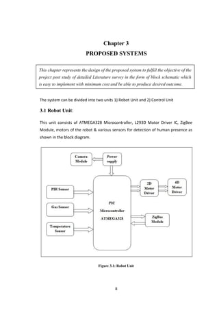
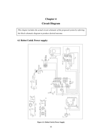
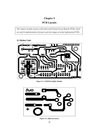
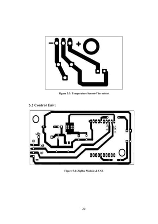
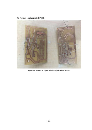
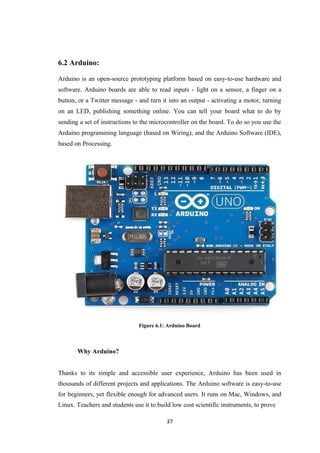
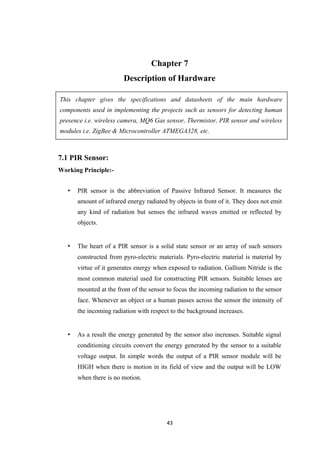
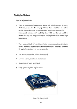
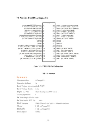
1) A robot unit comprising sensors like PIR, gas and temperature sensors, a wireless camera, and a ZigBee module for wireless communication. It is controlled by an Arduino microcontroller.
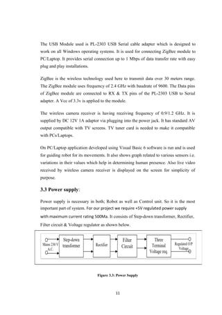
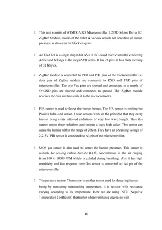
2) A control unit with a ZigBee USB module for communicating with the robot unit. It allows an operator to manually control and monitor the robot.
The system is designed to allow the robot to autonomously detect trapped humans using its onboard sensors, and transmit the location and sensor data back to the control unit to facilitate rescue operations. The overall


![Another static trait is the involuntary motion of internal organs, such as the heart and
lungs. This can be measured through skin-penetrating radio and ultrasound signals.
Finally, a relatively new avenue for human-sensing lies in scent detection [Pearce et
al. 2006].
Furthermore, CO2 levels have also been used to detect the presence of people, albeit
with slow response times [De Cubber and Marton 2009].
Dynamic traits are those that arise from human activity. We divide these into three
categories: external motion, gait, and vibrations. As for vibrations, these are the
pressure waves that people produce either involuntarily (in the form of sounds and
vibrations from footsteps, for example) or voluntarily (in the form of speech), which
can be measured with accelerometers and microphones, respectively.
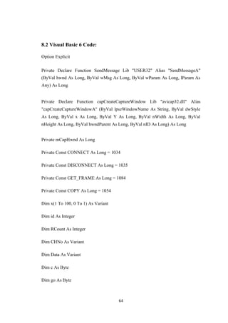
2.2 Sensor classification:
On basis of many different human traits that can be used for identifying human
presence large no. of sensors are available. Of which we limit ourselves to a selection
of approaches which are either the most useful, the most ubiquitous, or the most
ingenious. We discuss these in the context of similar solutions to illustrate the
advantages and disadvantages of each.
Binary Sensors:
A variety of sensing modalities can be grouped into the broad category of “binary
sensors". In the context of human-sensing, binary sensors are those that return logic 1
if human presence is detected within a certain sensing area, otherwise returning logic
0. The modality of binary sensors includes sensors such as break-beams, contact
sensors, PIRs, and binary Doppler-shift sensors, all of which are currently used in
resource-constrained scenarios. In single-node configuration, binary sensors can only
be used to detect presence, and nothing more.
4](https://image.slidesharecdn.com/19e5fc7d-ed29-4b62-8a3a-4463903a6082-161217232126/85/Degree-Project-12-320.jpg)


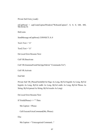


![REFERENCES
THIAGO TEIXEIRA Yale University, GERSHON DUBLON Massachusetts
Institute of Technology and ANDREAS SAVVIDES Yale University-“A
Survey of Human-Sensing:
Methods for Detecting Presence, Count, Location, Track, and
Identity” ACM Computing Surveys, Vol. V, No. N, 20YY.
Geetha Bharathi.V.S PG Student, Department of ECE, Easwari Engineering
College, Chennai, TN, India , Dr.S.Sudha Professor, Department of ECE,
Easwari Engineering College, Chennai, TN, India-“Alive Human Detection in
Disaster Zones using Manually Controlled Robots”
IJIRCCE Vol. 3, Special Issue 2, March 2015.
Trupti B. Bhondve PG student[VLSI], Dept. of E&TC , Dr.D.Y.Patil College
of Engineering, University of Pune, Ambi, Pune, India, Prof.R.Satyanarayan
Assistant Professor, Dept. of E&TC , Dr.D.Y.Patil College of Engineering,
University of Pune, Ambi, Pune, India, Prof. Moresh Mukhedkar Assistant
Professor, Dept. of E&TC , Dr.D.Y.Patil College of Engineering, University
of Pune, Ambi, Pune, India-“Mobile Rescue Robot for Human Body
Detection in Rescue Operation of Disaster”
IJIRCCE Vol. 3, Issue 6, June 2014.
Rajeev Joshi *, Pratap Chandra Poudel **, Pankaj Bhandari Department of
Electronics & Communication, N.I.T, Raichur, Karnataka, India-“An
Embedded Autonomous Robotic System for Alive Human Body Detection
and Rescue Operation”
International Journal of Scientific and Research Publications, Volume 4, Issue
5, May 2014
Basic Electronics – B.Ram
Digital Electronics – R.P.Jain
74](https://image.slidesharecdn.com/19e5fc7d-ed29-4b62-8a3a-4463903a6082-161217232126/85/Degree-Project-83-320.jpg)