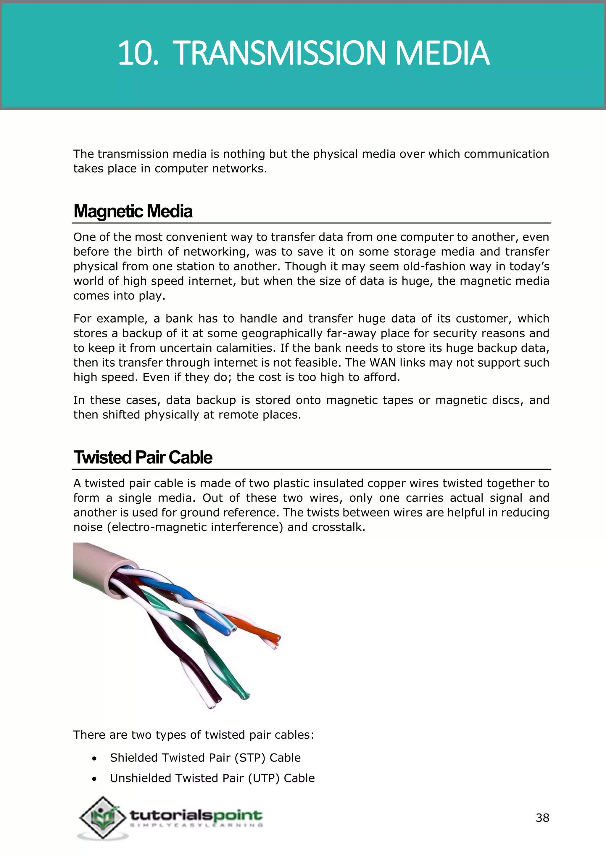
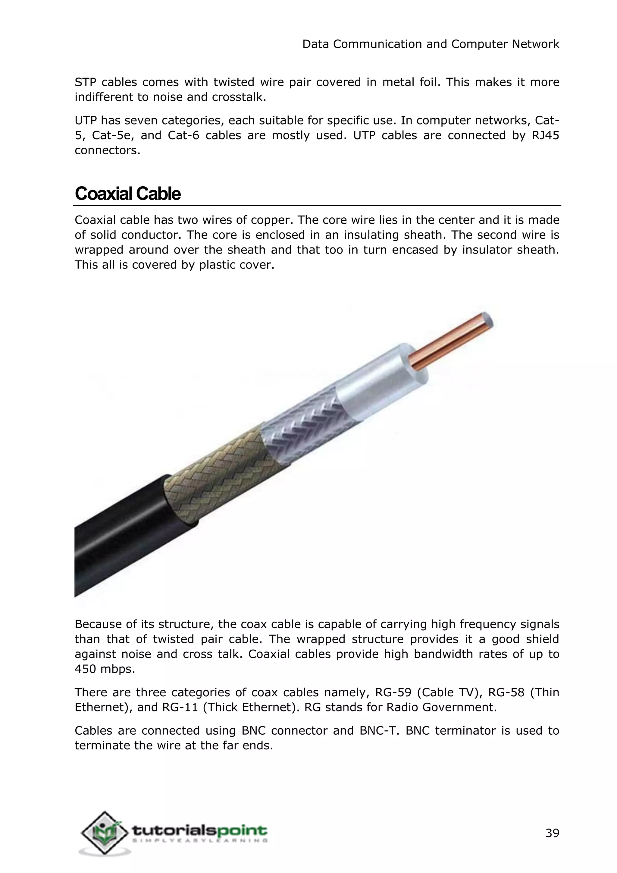
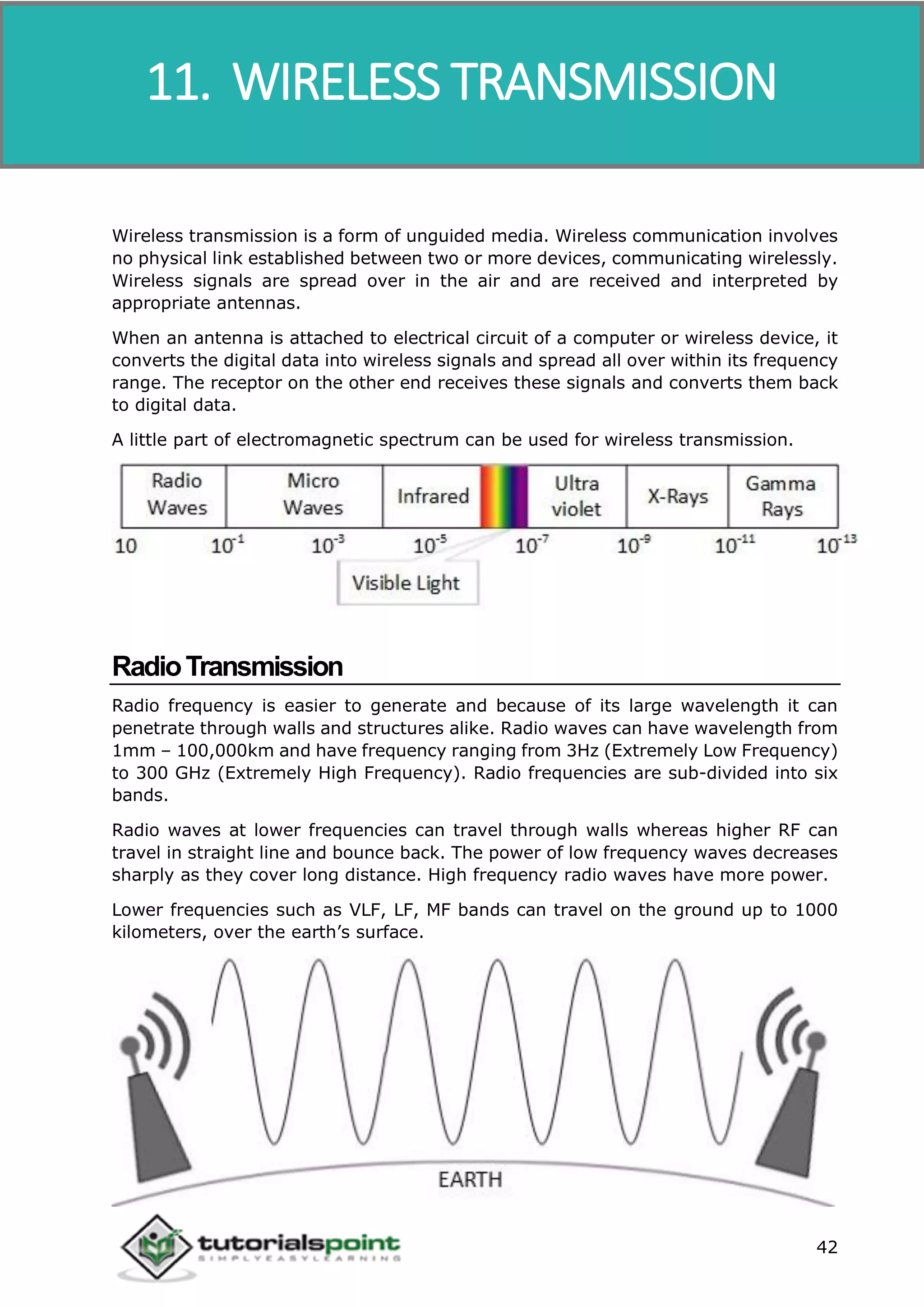
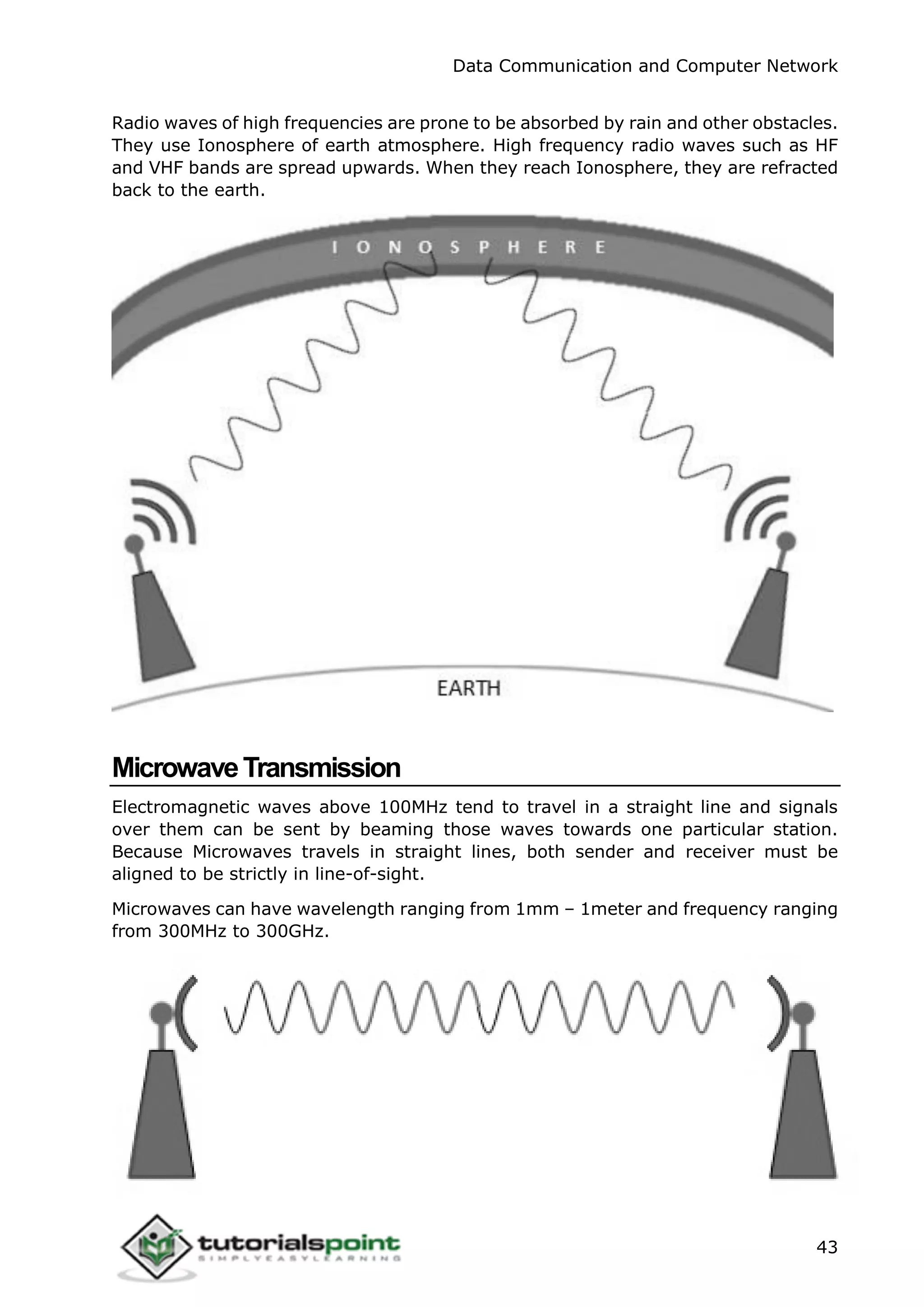
This document provides an overview of data communication and computer networks. It discusses different types of computer networks including personal area networks (PAN), local area networks (LAN), metropolitan area networks (MAN), wide area networks (WAN) and internetworks. It also describes common LAN technologies like Ethernet, Fast Ethernet and Gigabit Ethernet. Additionally, it covers various network topologies, models, security aspects and layers of the OSI model.


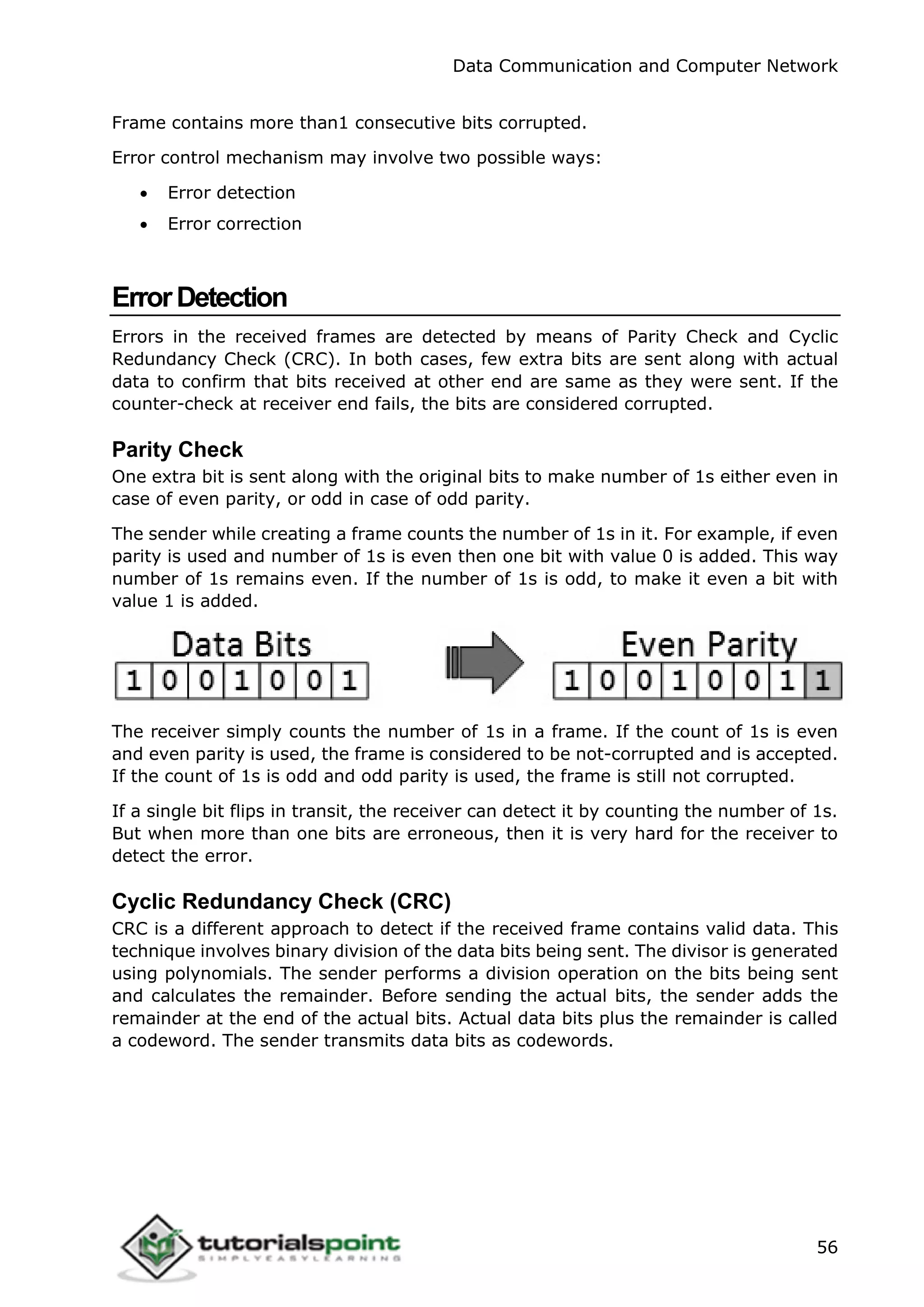


![01_-_W01L01_-_Introduction[1].pp free tx](https://cdn.slidesharecdn.com/ss_thumbnails/01-w01l01-introduction1-240627064011-cf787583-thumbnail.jpg?width=640&height=640&fit=bounds)


