Downloaded 159 times
![1. Crossbar input interconnect length Linput= (M . N). PR (Equation 1)
2. Horizontal spacing between crossbars = N . PR (Equation 2)
3. Vertical spacing between crossbars = 2*(NCOLS -1). N . PR (Equation 3)
4. LINPUT = [(M . N ) . PR ] + [(NCOLS -1) . LCS ] +[(2 . (NCOLS - 1) . N . PR ). (N ROWS - 1)+ [
((N ROWS -1) . WCS ] + [(NCOLS -1) . N . PR ] (Equation 4)
5. LOUTPUT = M . N . PR (Equation 5)
6. A = (2 . M . N . PR . NCOLS . LCOLS + (NCOLS - 1) . N . PR ).{[2 . (NCOLS - 1) . N . PR ] . (N R - 1)
+ PR .WCS } (Equation 6)](https://image.slidesharecdn.com/print-slide-150605051450-lva1-app6891/75/Cross-Bar-Switching-8-2048.jpg)


This document discusses the design of a 32x32 crossbar switching system. It defines crossbar switching as a network topology that allows any input port to connect to any output port without blocking. The document outlines the objectives, background, theory, existing technologies, planning technologies to apply, aspects and constraints to consider, analysis of results, and conclusions regarding crossbar switching design and simulation.
Introduction to the faculty and presentation context about telecommunication switching system and crossbar switching.
Objectives include designing and analyzing crossbar switch technology and its compatibility requirements.
Discusses the upgrade of client network and analysis results based on HSPICE simulation for crossbar switches.
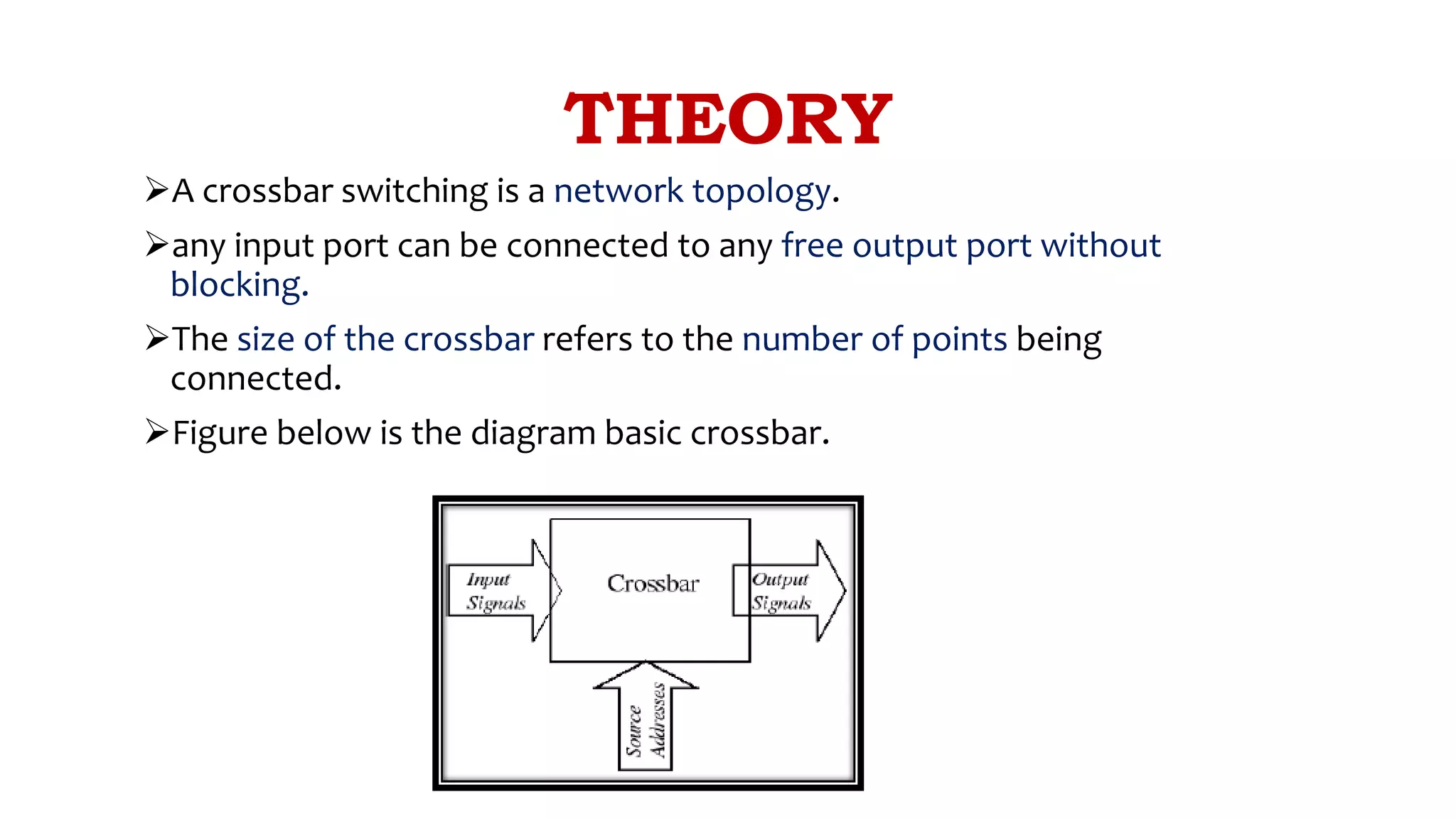
Explains crossbar switching as a non-blocking network topology that connects any input to any output.
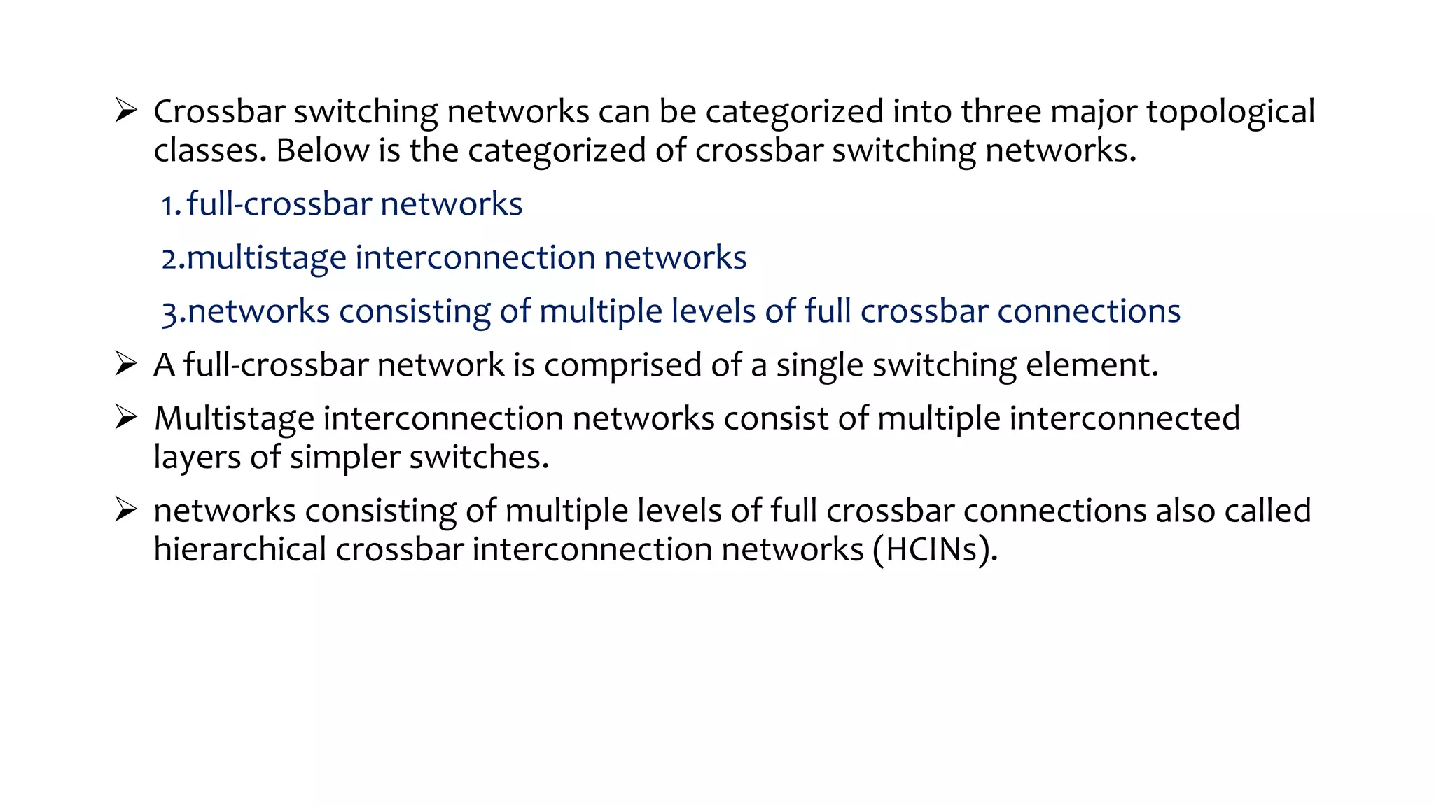
Categorizes crossbar networks into full-crossbar, multistage interconnection, and hierarchical networks.
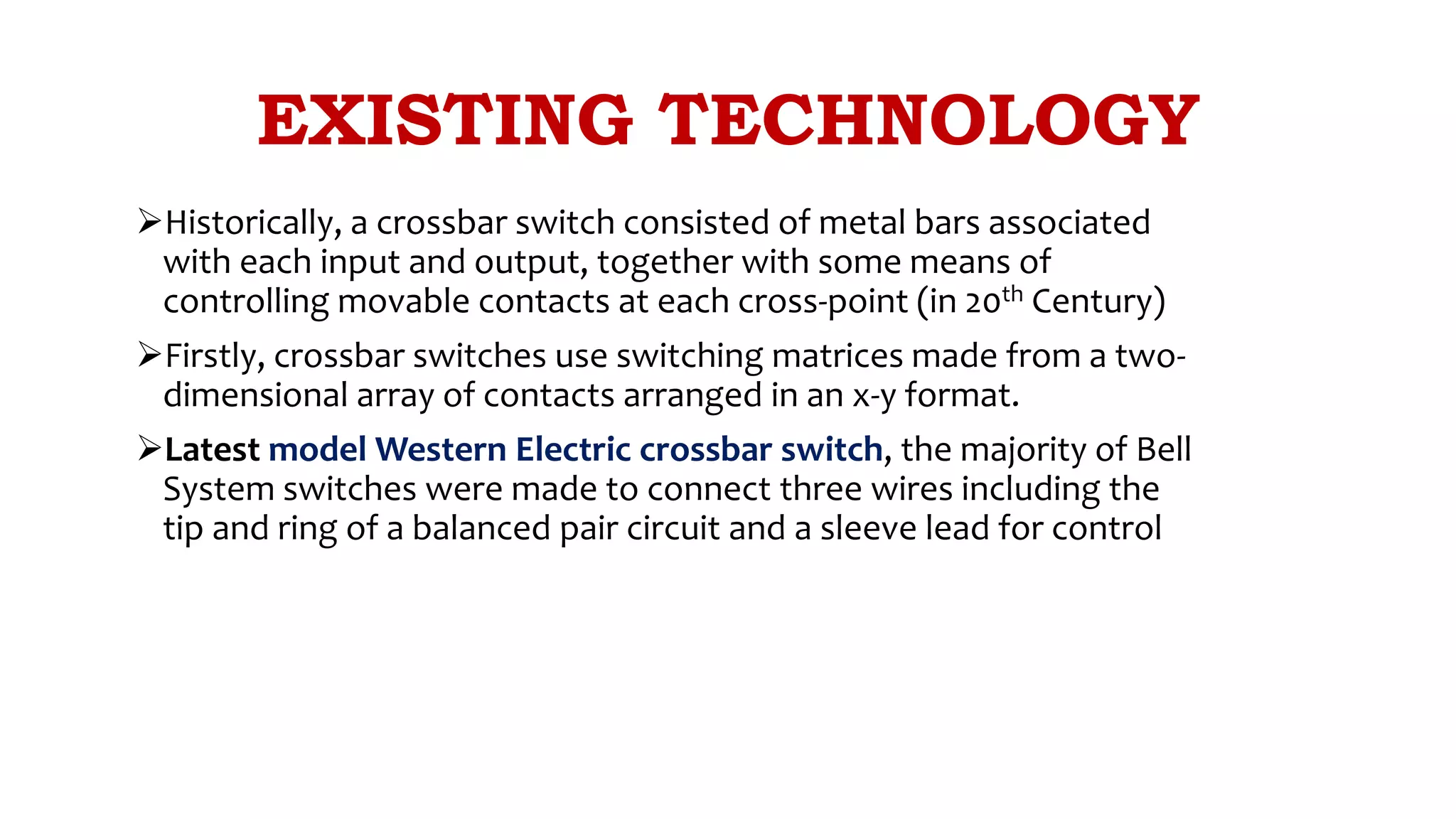
Overview of historical development of crossbar switches and the technology used in 20th Century.
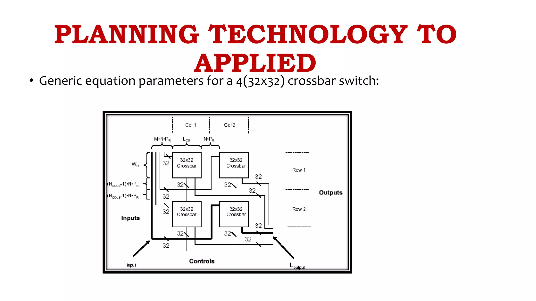
Presents design parameters and equations for input length and spacing in a 32x32 crossbar switch.
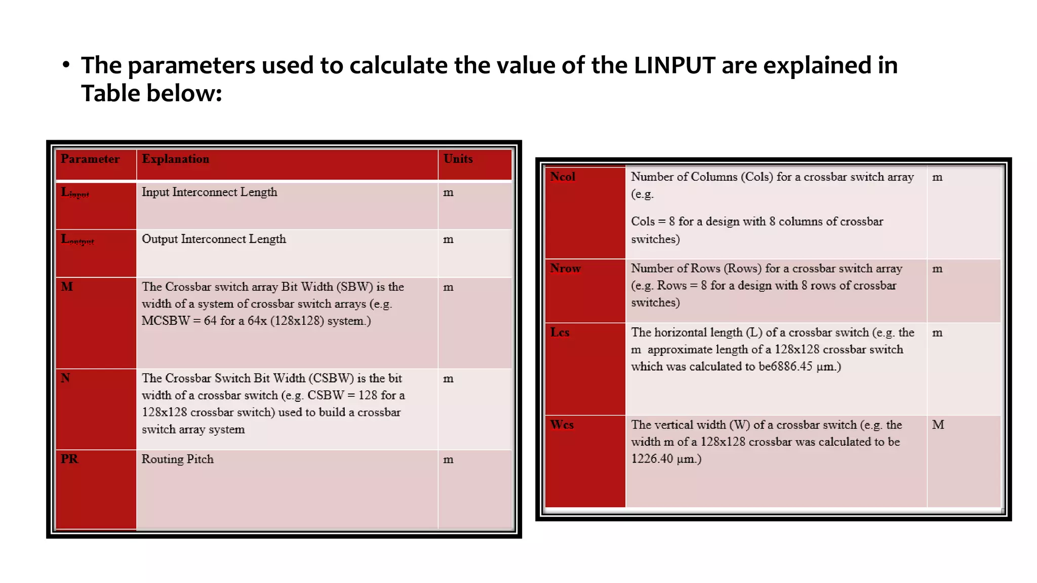
Illustrates the parameters used for calculating input parameters in the design of a crossbar switch.
Discusses crucial design aspects such as the switching matrix, signal frequency, and multiplexing.
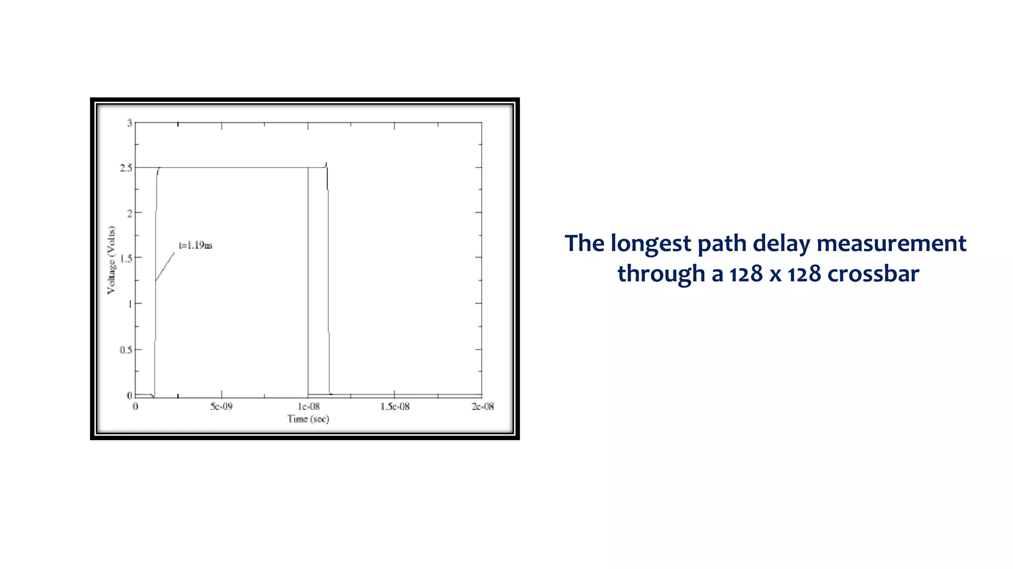
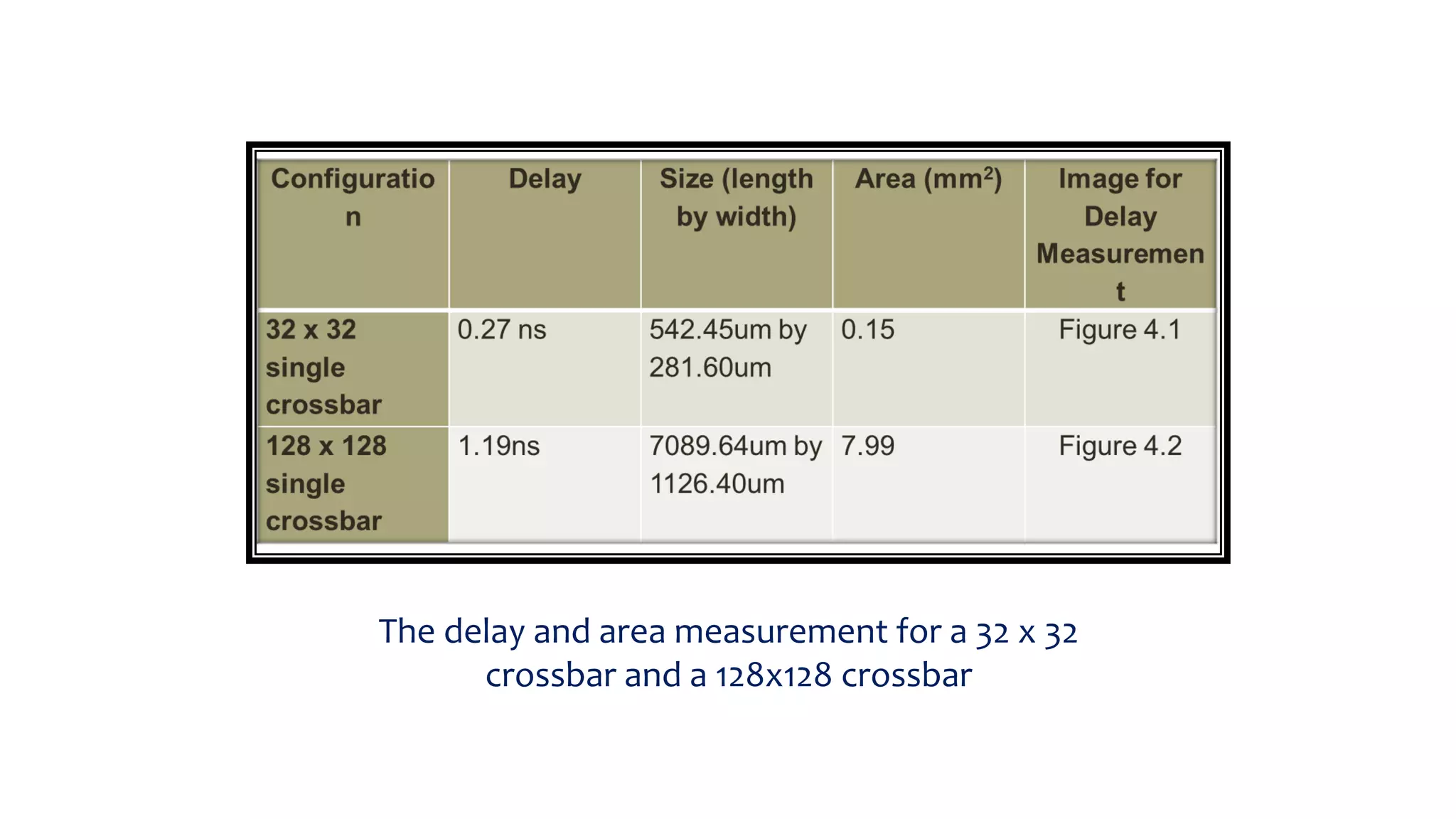
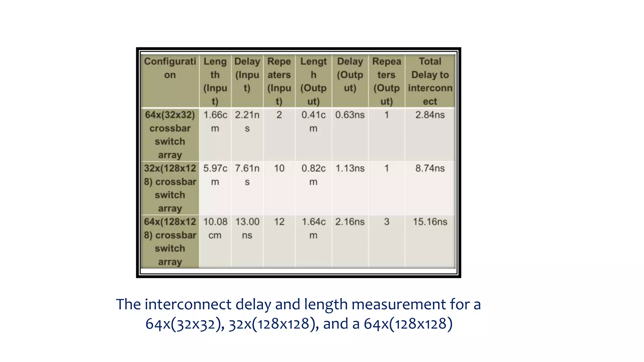
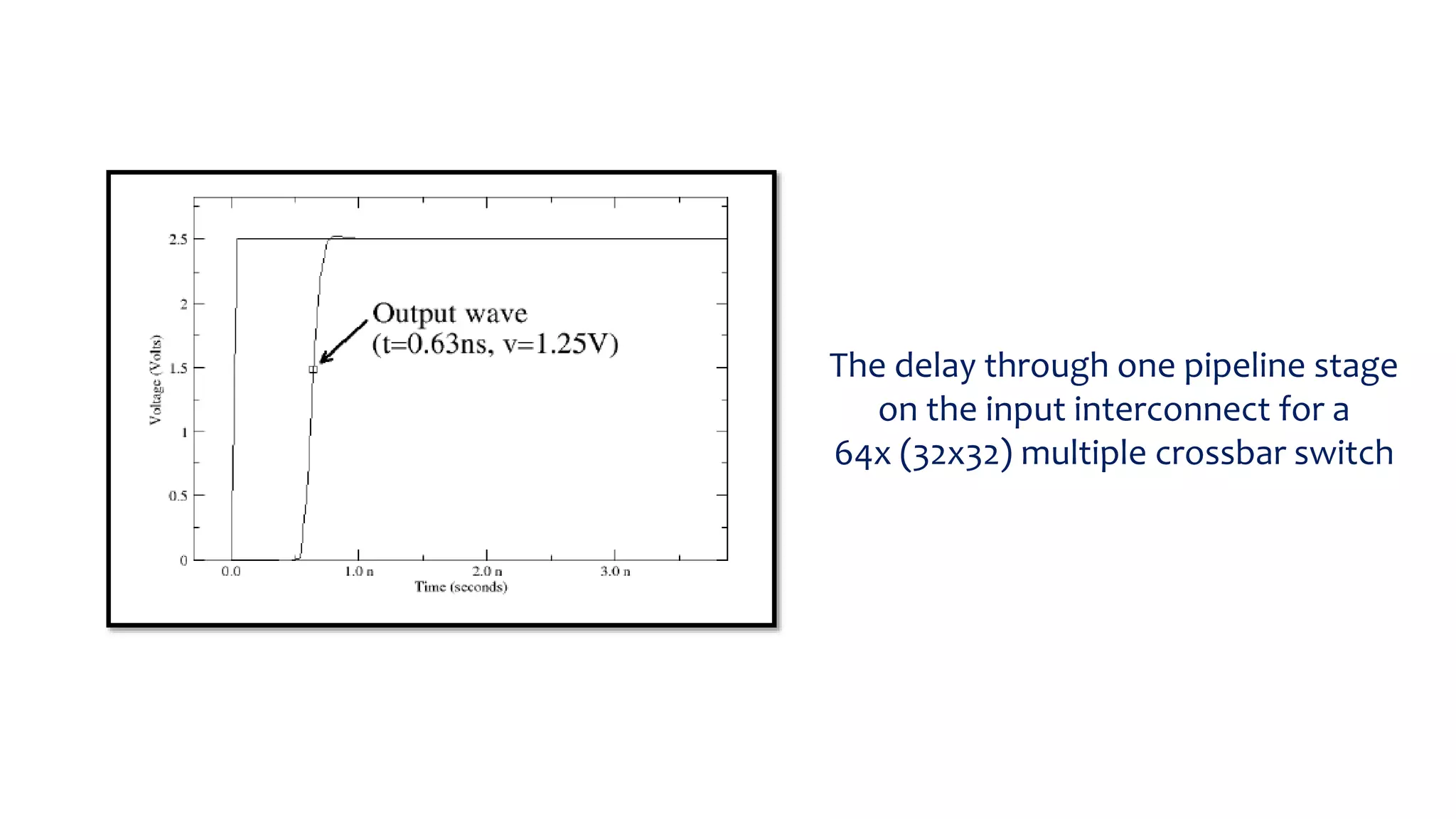
Analyzes delay measurement results for different crossbar configurations including 32x32 and 128x128.
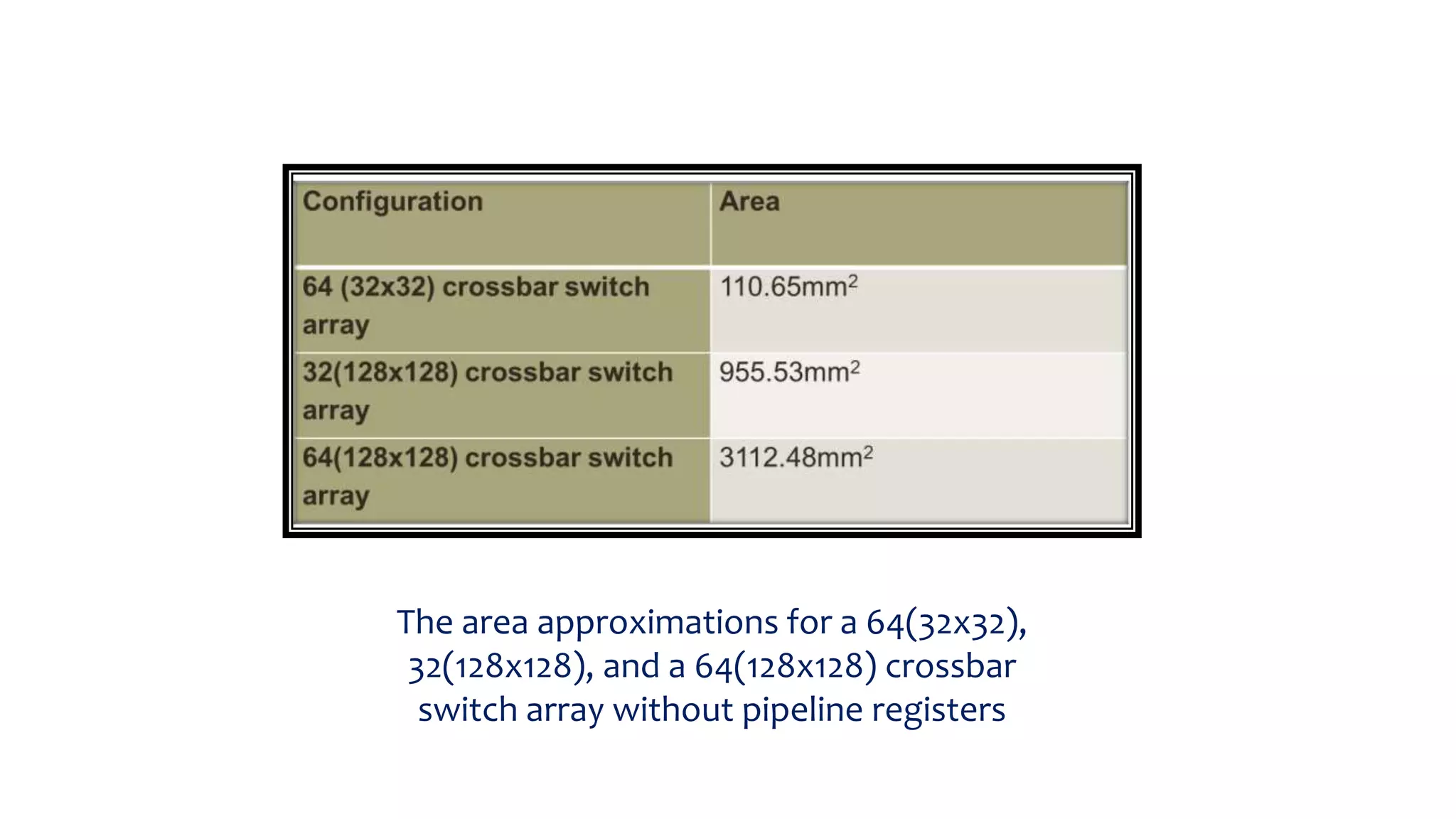
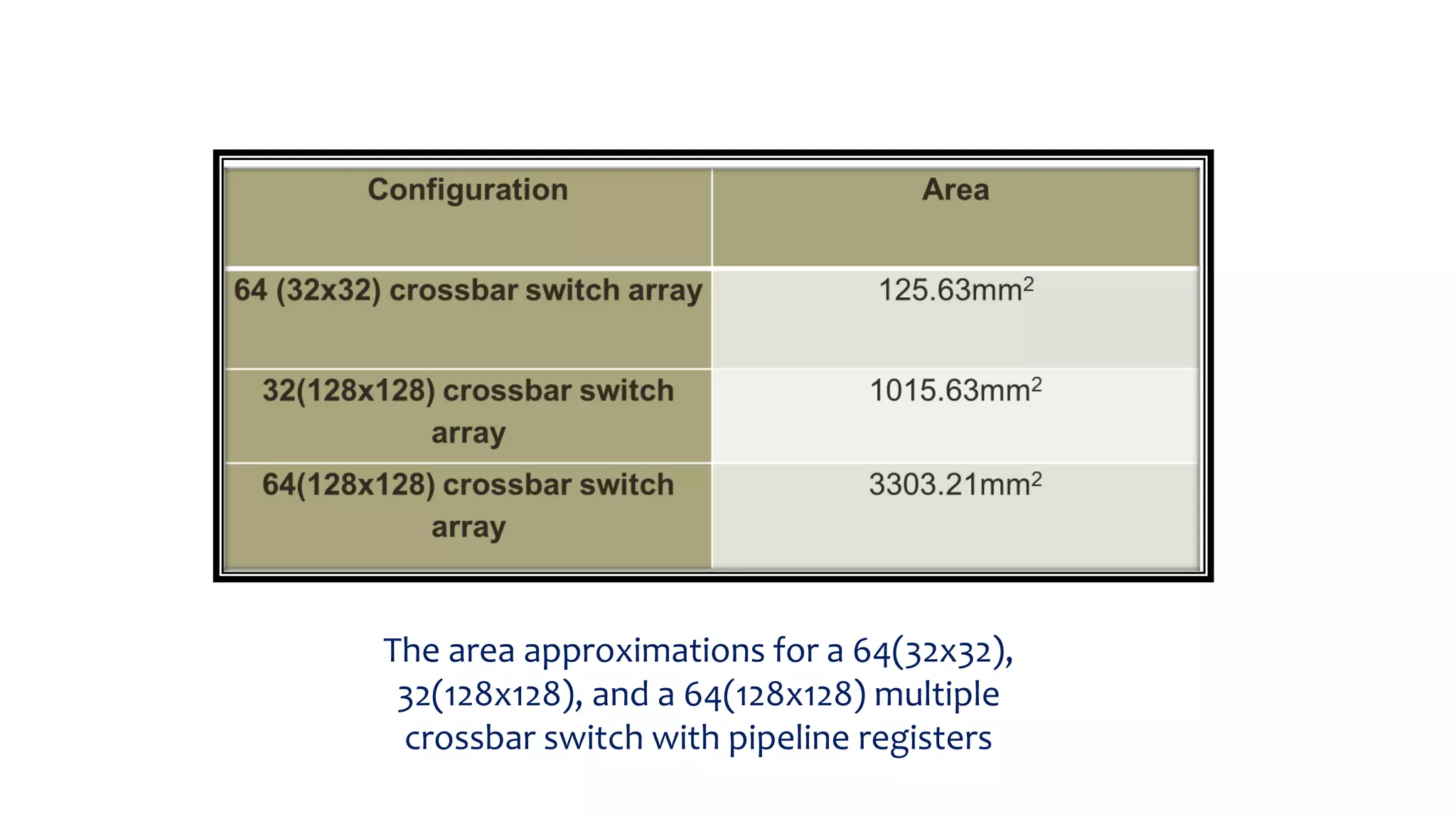
Details area approximations for multiple configurations of crossbar switches with and without registers.
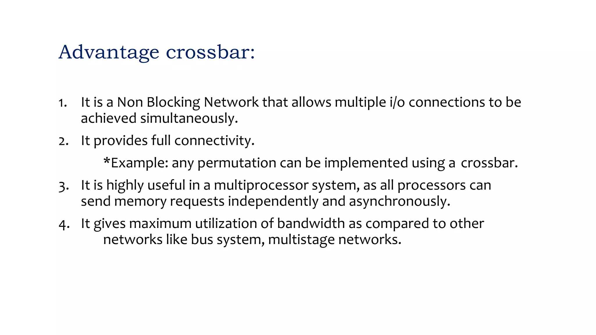
Highlights advantages including non-blocking nature, full connectivity, and bandwidth utilization.
Outlines disadvantages such as single-layered structure and connections at each switch point.
Summarizes understanding of crossbar switch technology, comparisons, compatibility, and simulations.