Downloaded 1,037 times
![Scattering Loss Factor ρ s = exp[-8(Πσ h sinθ i ) 2 ]I 0 [8(Πσ h cosθ i ) 2 ] where , I 0 is the Bessel function of the first kind and zero order σ h is the standard deviation of the surface height, h about the mean surface height θ i is the angle of incidence](https://image.slidesharecdn.com/propagationmechanisms-111105010345-phpapp01/75/Propagation-mechanisms-16-2048.jpg)

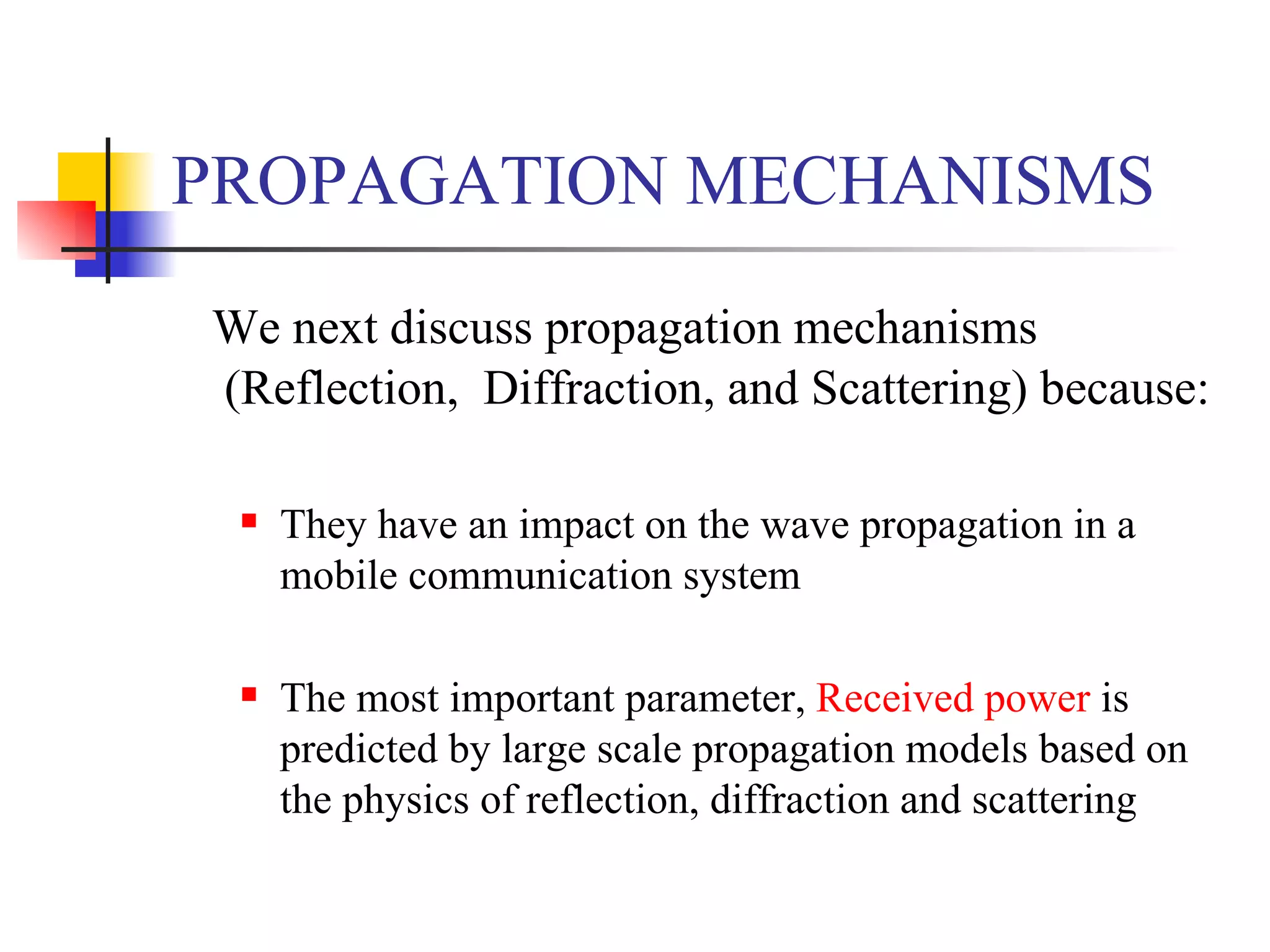
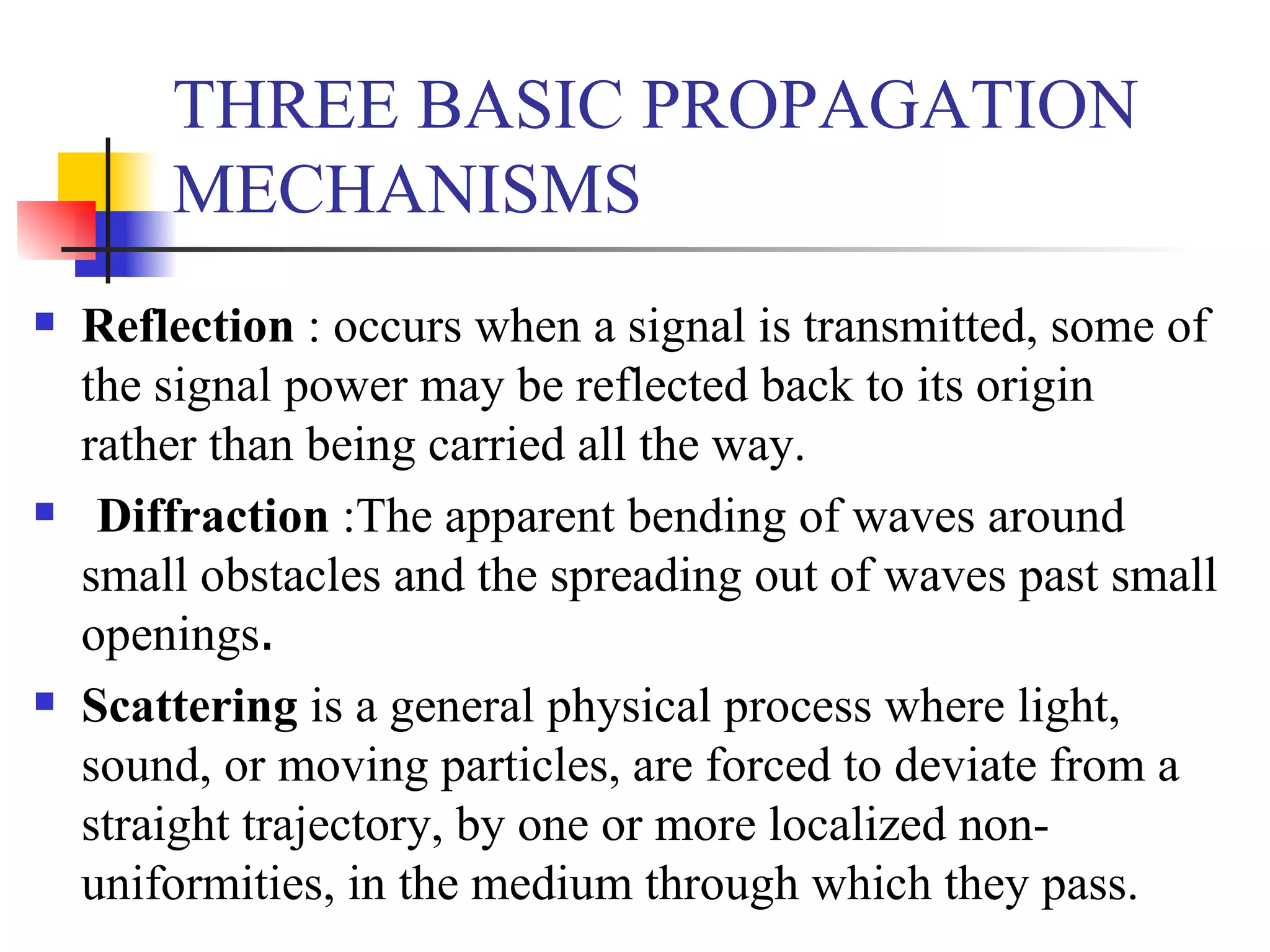
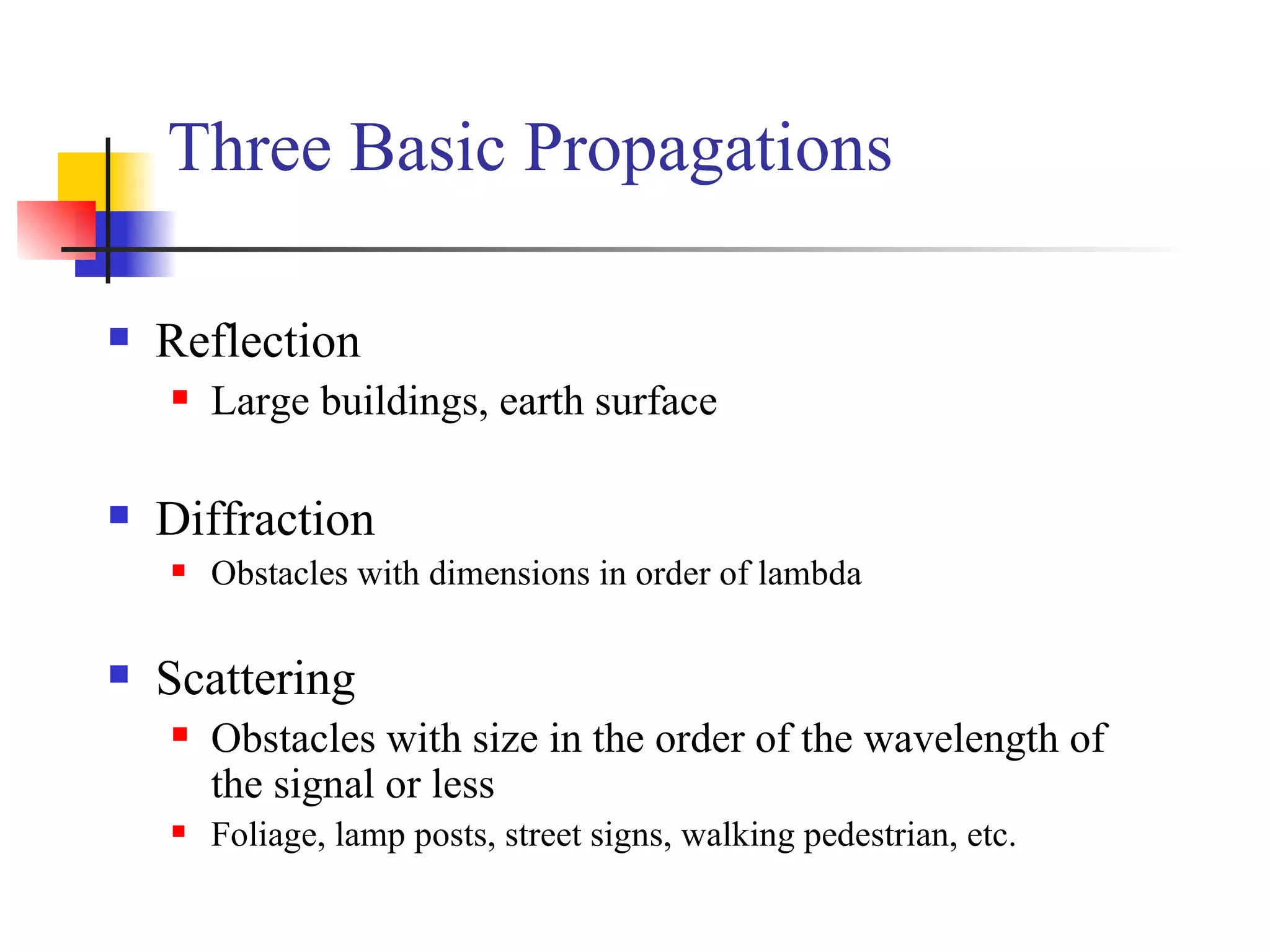
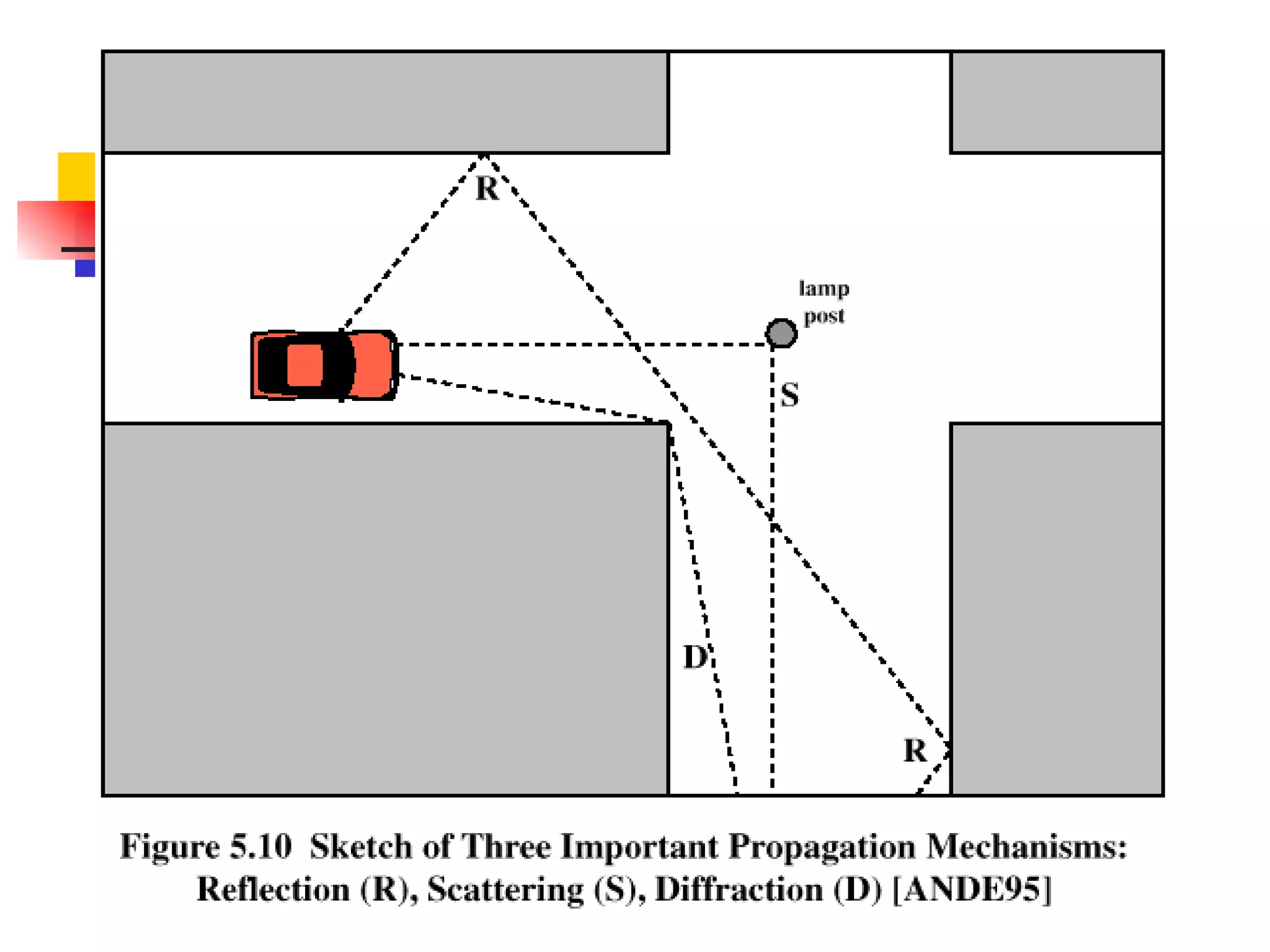
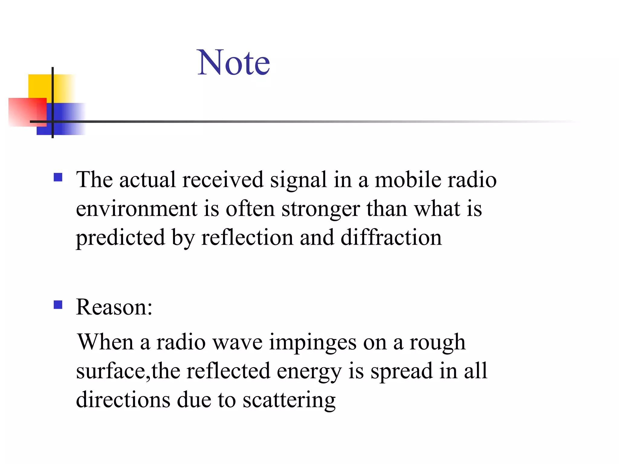
There are 3 main propagation mechanisms in mobile communication systems: 1. Reflection occurs when signals bounce off surfaces like buildings and earth. 2. Diffraction is when signals bend around obstacles like hills and buildings. 3. Scattering is when signals are deflected in many directions by small obstacles like trees and signs. These 3 mechanisms impact the received power and must be considered in propagation models.