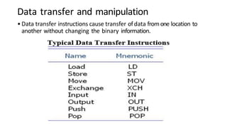
The document outlines the basics of computer organization and design, focusing primarily on instruction codes, computer registers, and the instruction cycle. It describes the structure and function of various types of instructions, including memory reference, register reference, and central processing unit instruction formats, as well as different addressing modes and architectures such as CISC and RISC. Key components include the operation code, data and address registers, and the stages of executing instructions within a CPU.
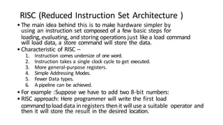
![•Logical Instructions: These instructions perform logical operations like AND, OR, XOR,
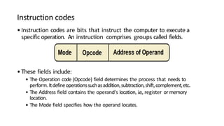
and NOT using registers as operands. Examples include:
•AND (Bitwise AND)
•OR (Bitwise OR)
•XOR (Bitwise XOR)
•NOT (Bitwise NOT)
•For example
•AND R1, R2 ; Perform bitwise AND of R1 and R2
•OR R3, R4 ; Perform bitwise OR of R3 and R4
•Data Transfer Instructions: These instructions move data between registers or between
registers and memory. Examples include:
•MOV (Move data between registers or memory locations)
•LOAD (Load data from memory into a register)
•STORE (Store data from a register into memory)
•For example:
•MOV R1, R2 ; Move data from R2 to R1
•LOAD R3, [R4] ; Load data from memory address stored in R4 into R3](https://image.slidesharecdn.com/comodule2-240601005839-77cd6d86/85/computer-organisation-and-architecture-Module-2-pptx-12-320.jpg)
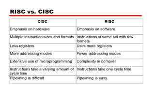
![•Immediate Addressing Mode :-> The operand is directly provided
as a constant value. No extra computations are required tocalculate
effective address (EA).Wehave noneedtostore the value ofthe constant in
memoryor register. Wecan directly use it from instruction.
•For example:->
•ADD 10 (AC = AC+10)
•MOV AL, 30H (move the data (30H) into AL register)
•Direct Addressing Mode:-> Theoperand ofinstruction contains the
address ofthe memorylocation.It also called an absolute addressing
mode.
•For example:->
•ADD AL,[0302] //add the contents of address 0302 to AL](https://image.slidesharecdn.com/comodule2-240601005839-77cd6d86/85/computer-organisation-and-architecture-Module-2-pptx-19-320.jpg)
![1
.
•Indirect Addressing Mode :-> The address field of the
instruction contains the address of memory location. That
memory location contains the effective address of the require
d .Two references of memory are required to fetch the required
•For example :->
ADD X in indirect addressing mode will perform in the
following way
AC← AC + [[X]]
2. LOAD R1,@100 ( Load the content of memory address stored at
memory address 100 to the register R1.)
•Register Direct Addressing Mode:-> The address field of the
instruction specifies to a CPU register which contains the
operand. There is no need for memory access to fetch the
operand.](https://image.slidesharecdn.com/comodule2-240601005839-77cd6d86/85/computer-organisation-and-architecture-Module-2-pptx-20-320.jpg)
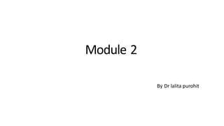
![•ADD R in register direct addressing mode will perform in the
following way
•For example :-> AC← AC + [R]
•Register Indirect Addressing Mode :-> The address field of the
instruction specifies toa CPUregister which provides the effective
address ofthe operand.Thereis Only onememory reference is required
to fetch the operand.
•For Example :->
•ADD R in register indirect addressing mode will perform in the
following way
•AC← AC + [[R]]](https://image.slidesharecdn.com/comodule2-240601005839-77cd6d86/85/computer-organisation-and-architecture-Module-2-pptx-21-320.jpg)
![•Auto-Increment and decrement Addressing Mode:-> This
addressing modeis a special case ofRegister Indirect Addressing
Mode. Auto-increment and decrement is used toaccess the data
in sequence from memory.
•For example :->
•Add R1, (R2)+ or Add R1,(R2)-
•Indexed Addressing Mode:-> Operand-field contains the starting base
address ofthe array-memory block and the general register (index-
register) field will contain the index value.
•For example :->
•MOV AX, [SI +05]](https://image.slidesharecdn.com/comodule2-240601005839-77cd6d86/85/computer-organisation-and-architecture-Module-2-pptx-22-320.jpg)