Basic Computer Organization
InstructionCodes
The organization of the computer is defined by its internal registers, the timing and
control structure, and the set of instructions that it uses.
A computer instruction is a binary code that specifies a sequence of
microoperations for the computer.
An instruction code is a group of bits that instruct the computer to perform a
specific operation.
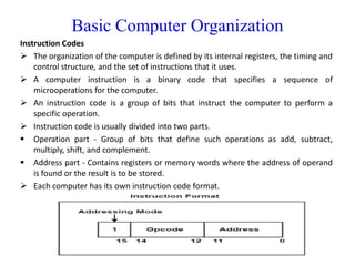
Instruction code is usually divided into two parts.
Operation part - Group of bits that define such operations as add, subtract,
multiply, shift, and complement.
Address part - Contains registers or memory words where the address of operand
is found or the result is to be stored.
Each computer has its own instruction code format.
3.
Basic Computer Organization
The operation code(op-code) of an instruction is a group of bits that define such
operations as add, subtract, multiply, shift, and complement.
The number of bits required for the operation code of an instruction depends on the
total number of operations available in the computer.(n bits for 2n operations)
An operation code is sometimes called a macro-operation because it specifies a set of
micro-operations.
Simplest way to organize computer is to have one processor register(Accumulator AC)
and an instruction code format with two parts.
First-Operation to be performed
Second – Address
The memory address tells the control where to find an operand in memory.
This operand is read from memory and used as the data to be operated on together
with the data stored in the processor register.
4.
Basic Computer Organization
ComputerRegisters - Need of Registers?
Computer instructions are normally stored in consecutive memory locations and are
executed sequentially one at a time.
The control reads an instruction from a specific address in memory and executes it. It
then continues by reading the next instruction in sequence and executes it, and so on.
This type of instruction sequencing needs a counter to calculate the address of the
next instruction after execution of the current instruction is completed.
It is also necessary to provide a register in the control unit for storing the instruction
code after it is read from memory.
The computer needs processor registers for manipulating data and a register for
holding a memory address.
5.
Basic Computer Organization
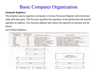
ComputerRegisters:
The simplest way to organize a computer is to have Processor Register and instruction
code with two parts. The first part specifies the operation to be performed and second
specifies an address. The memory address tells where the operand in memory will be
found.
List of Basic Registers:
6.
Basic Computer Organization
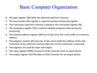
The data register (DR) holds the operand read from memory.
The accumulator (AC) register is a general purpose processing register.
The instruction read from memory is placed in the instruction register (IR).
The temporary register (TR) is used for holding temporary data during the
processing.
The memory address register (AR) has 12 bits since this is the width of a memory
address.
The program counter (PC) also has 12 bits and it holds the address of the next
instruction to be read from memory after the current instruction is executed.
Two registers are used for input and output.
The input register (INPR) receives an 8-bit character from an input device.
The output register (OUTR) holds an 8-bit character for an output device.
7.
Basic Computer Organization
ComputerInstructions:
Computer Instructions are the commands which is given by the user to the computer
to perform some specific function desired. Mostly the codes of the instruction are
written in binary language, i.e: 0’s and 1’s. ADD, JUMP, LOAD, etc are some of the
instructions used in processors.
Instruction Format
The basic computer has three instruction code formats each having 16 bits
1. Memory reference instructions
2. Register reference instructions
3. I/O instructions
The opcode part of the instruction contains three bits(3) and the meaning of the
remaining 13 bits depends on the operation code encountered.
8.
Basic Computer Organization
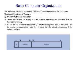
Theoperation part of an instruction code specifies the operation to be performed.
There are three types of formats:
1). Memory Reference Instruction
These instructions are mainly used to perform operations on operands that are
located in memory.
It uses 12 bits to specify the address, 3 bits for the opcode (000 to 110) and 1 bit
to specify the addressing mode (I). I is equal to 0 for direct address and 1 for
indirect address.
9.
Basic Computer Organization
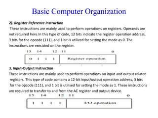
2).Register Reference Instruction
These instructions are mainly used to perform operations on registers. Operands are
not required here.In this type of code, 12 bits indicate the register operation address,
3 bits for the opcode (111), and 1 bit is utilized for setting the mode as 0. The
instructions are executed on the register.
3. Input-Output Instruction
These instructions are mainly used to perform operations on input and output related
registers. This type of code contains a 12-bit input/output operation address, 3 bits
for the opcode (111), and 1 bit is utilised for setting the mode as 1. These instructions
are required to transfer to and from the AC register and output device.
10.
Basic Computer Organization
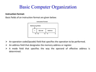
InstructionFormat:
Basic fields of an instruction format are given below:
An operation code(Opcode) field that specifies the operation to be performed.
An address field that designates the memory address or register.
A mode field that specifies the way the operand of effective address is
determined.
11.
Basic Computer Organization
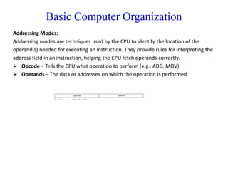
AddressingModes:
Addressing modes are techniques used by the CPU to identify the location of the
operand(s) needed for executing an instruction. They provide rules for interpreting the
address field in an instruction, helping the CPU fetch operands correctly.
Opcode – Tells the CPU what operation to perform (e.g., ADD, MOV).
Operands – The data or addresses on which the operation is performed.
12.
Basic Computer Organization
Typesof Addressing Modes:
1. Immediate Mode
In this mode, the operand is specified in the instruction itself. An immediate mode
instruction has an operand field rather than the address field.
For example: ADD 7, which says Add 7 to contents of accumulator. 7 is the operand
here.
2. Register Addressing Mode
In this mode the operand is stored in the register and this register is present in CPU.
The instruction has the address of the Register where the operand is stored.
Ex: mov eax, ebx
3. Register Indirect Mode
In this mode, the instruction specifies the register whose contents give us the address
of operand which is in memory. Thus, the register contains the address of operand
rather than the operand itself.
13.
Basic Computer Organization
Typesof Addressing Modes:
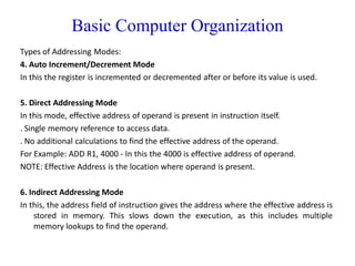
4. Auto Increment/Decrement Mode
In this the register is incremented or decremented after or before its value is used.
5. Direct Addressing Mode
In this mode, effective address of operand is present in instruction itself.
. Single memory reference to access data.
. No additional calculations to find the effective address of the operand.
For Example: ADD R1, 4000 - In this the 4000 is effective address of operand.
NOTE: Effective Address is the location where operand is present.
6. Indirect Addressing Mode
In this, the address field of instruction gives the address where the effective address is
stored in memory. This slows down the execution, as this includes multiple
memory lookups to find the operand.
14.
Basic Computer Organization
Typesof Addressing Modes:
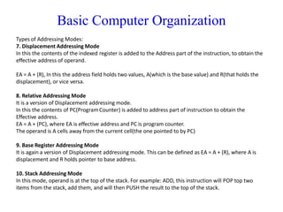
7. Displacement Addressing Mode
In this the contents of the indexed register is added to the Address part of the instruction, to obtain the
effective address of operand.
EA = A + (R), In this the address field holds two values, A(which is the base value) and R(that holds the
displacement), or vice versa.
8. Relative Addressing Mode
It is a version of Displacement addressing mode.
In this the contents of PC(Program Counter) is added to address part of instruction to obtain the
Effective address.
EA = A + (PC), where EA is effective address and PC is program counter.
The operand is A cells away from the current cell(the one pointed to by PC)
9. Base Register Addressing Mode
It is again a version of Displacement addressing mode. This can be defined as EA = A + (R), where A is
displacement and R holds pointer to base address.
10. Stack Addressing Mode
In this mode, operand is at the top of the stack. For example: ADD, this instruction will POP top two
items from the stack, add them, and will then PUSH the result to the top of the stack.
15.
Basic Computer Organization
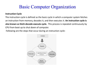
InstructionCycle
The instruction cycle is defined as the basic cycle in which a computer system fetches
an instruction from memory, decodes it, and then executes it. An instruction cycle is
also known as fetch-decode-execute cycle. This process is repeated continuously by
CPU from boot up to shut down of computer.
Following are the steps that occur during an instruction cycle:
16.
Basic Computer Organization
1.Fetch the Instruction
The CPU uses the program counter (PC) to access the memory location where the next
instruction is stored. The instruction is fetched and placed in the instruction register
(IR). At the end of the fetch operation, PC is incremented by 1 and it then points to the
next instruction to be executed.
2. Decode the Instruction
The instruction in the IR is executed by the decoder.
3. Read the Effective Address
If the instruction has an indirect address, the effective address is read from the
memory. Otherwise operands are directly read in case of immediate operand
instruction.
4. Execute the Instruction
The Control Unit passes the information in the form of control signals to the functional
unit of CPU. The result generated is stored in main memory or sent to an output
device.
The cycle is then repeated by fetching the next instruction. Thus in this way the
instruction cycle is repeated continuously.
17.
Basic Computer Organization
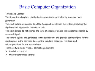
Timingand Control:
The timing for all registers in the basic computer is controlled by a master clock
generator.
The clock pulses are applied to all flip-flops and registers in the system, including the
flip-flops and registers in the control unit.
The clock pulses do not change the state of a register unless the register is enabled by
a control signal.
The control signals are generated in the control unit and provide control inputs for the
multiplexers in the common bus, control inputs in processor registers, and
microoperations for the accumulator.
There are two major types of control organization:
Hardwired control
Microprogrammed control
18.
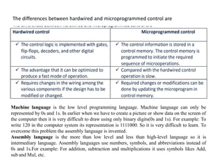
The differences betweenhardwired and microprogrammed control are
Machine language is the low level programming language. Machine language can only be
represented by 0s and 1s. In earlier when we have to create a picture or show data on the screen of
the computer then it is very difficult to draw using only binary digits(0s and 1s). For example: To
write 120 in the computer system its representation is 1111000. So it is very difficult to learn. To
overcome this problem the assembly language is invented.
Assembly language is the more than low level and less than high-level language so it is
intermediary language. Assembly languages use numbers, symbols, and abbreviations instead of
0s and 1s.For example: For addition, subtraction and multiplications it uses symbols likes Add,
sub and Mul, etc.
19.
Register Transfer andMicro operations
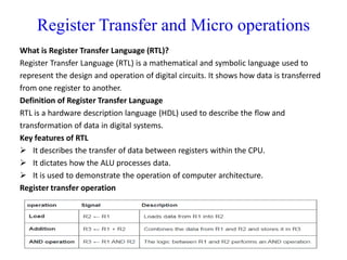
What is Register Transfer Language (RTL)?
Register Transfer Language (RTL) is a mathematical and symbolic language used to
represent the design and operation of digital circuits. It shows how data is transferred
from one register to another.
Definition of Register Transfer Language
RTL is a hardware description language (HDL) used to describe the flow and
transformation of data in digital systems.
Key features of RTL
It describes the transfer of data between registers within the CPU.
It dictates how the ALU processes data.
It is used to demonstrate the operation of computer architecture.
Register transfer operation
20.
Register Transfer andMicro operations
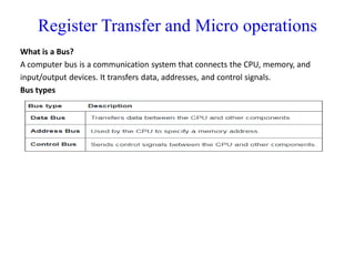
What is a Bus?
A computer bus is a communication system that connects the CPU, memory, and
input/output devices. It transfers data, addresses, and control signals.
Bus types
21.
Register Transfer andMicro operations
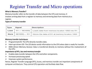
What is Memory Transfer?
Memory transfer refers to the transfer of data between the CPU and memory. It
involves writing data from a register to memory and retrieving data from memory to a
register.
Types of memory transfer
Memory transfer techniques
Programmed I/O: The CPU directly transfers data.
Interrupt-driven I/O: The I/O device sends information to the CPU when data is ready for transfer.
DMA (Direct Memory Access): Data is transferred directly to memory without the involvement of
the CPU.
Importance of RTL, bus and memory transfer
Enables data transfer between the CPU and other components.
Increases processing speed.
Improves system performance.
Hence, Register Transfer Language (RTL), buses, and memory transfer are important components of
computer architecture. They control CPU operation and facilitate data flow.
22.
Register Transfer andMicro operations
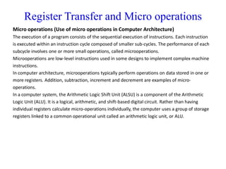
Micro operations (Use of micro operations in Computer Architecture)
The execution of a program consists of the sequential execution of instructions. Each instruction
is executed within an instruction cycle composed of smaller sub-cycles. The performance of each
subcycle involves one or more small operations, called microoperations.
Microoperations are low-level instructions used in some designs to implement complex machine
instructions.
In computer architecture, microoperations typically perform operations on data stored in one or
more registers. Addition, subtraction, increment and decrement are examples of micro-
operations.
In a computer system, the Arithmetic Logic Shift Unit (ALSU) is a component of the Arithmetic
Logic Unit (ALU). It is a logical, arithmetic, and shift-based digital circuit. Rather than having
individual registers calculate micro-operations individually, the computer uses a group of storage
registers linked to a common operational unit called an arithmetic logic unit, or ALU.
23.
Register Transfer andMicro operations
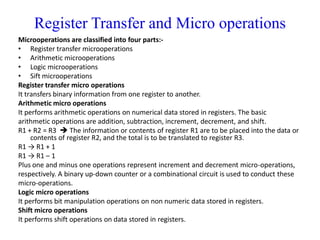
Microoperations are classified into four parts:-
• Register transfer microoperations
• Arithmetic microoperations
• Logic microoperations
• Sift microoperations
Register transfer micro operations
It transfers binary information from one register to another.
Arithmetic micro operations
It performs arithmetic operations on numerical data stored in registers. The basic
arithmetic operations are addition, subtraction, increment, decrement, and shift.
R1 + R2 = R3 The information or contents of register R1 are to be placed into the data or
contents of register R2, and the total is to be translated to register R3.
R1 → R1 + 1
R1 → R1 – 1
Plus one and minus one operations represent increment and decrement micro-operations,
respectively. A binary up-down counter or a combinational circuit is used to conduct these
micro-operations.
Logic micro operations
It performs bit manipulation operations on non numeric data stored in registers.
Shift micro operations
It performs shift operations on data stored in registers.