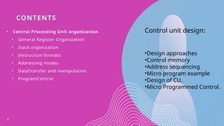
CONTENTS
• Central ProcessingUnit organization
• General Register Organization
• Stack organization
• Instruction formats
• Addressing modes
• DataTransfer and manipulation
• ProgramControl
6
Control unit design:
•Design approaches
•Control memory
•Address sequencing
•Micro program example
•Design of CU.
•Micro Programmed Control.
7.
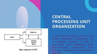
CENTRAL
PROCESSING UNIT
ORGANIZATION
A CentralProcessing Unit is the
most important component of
a computer system. A CPU is
hardware that performs data
input/output, processing, and
storage functions for a computer
system.
8.
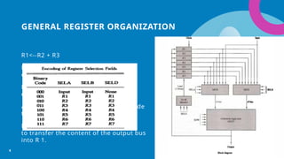
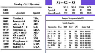
GENERAL REGISTER ORGANIZATION
R1<--R2+ R3
MUX A selector (SELA): to place the
content of R2 into bus A.
MUX B selector (SELB): to place the
content of R3 into bus B.
ALU operation selector (OPR): to provide
the arithmetic addition A+ B.
Decoder destination selector (SELD):
to transfer the content of the output bus
into R 1.
8
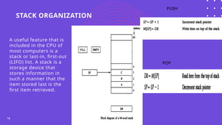
STACK ORGANIZATION
10
A usefulfeature that is
included in the CPU of
most computers is a
stack or last-in, first-out
(LIFO) list. A stack is a
storage device that
stores information in
such a manner that the
item stored last is the
first item retrieved.
PUSH
POP
11.
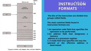
INSTRUCTION
FORMATS
Click icon toadd picture
The bits of the instruction are divided into
groups called fields.
The most common fields found in
instruction formats are:
1.An operation code field that specifies the
operation to be performed.
2.An address field that designates a
memory
address or a processor register.
3. A mode field that specifies the way the
operand or the effective address is
determined.
12.
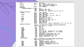
SAMPLE INSTRUCTIONS
12
1. ADDR1, R2, R3
2. ADD R1, R2
3. MOV R1, R2
4. ADD R1, A, B R1<-- M[A] + M[B]
5. ADD R2, C, D R2<-- M[C] + M[D]
6. MUL X, R1, R2 M[X] <-- R1•R2
• MOV R1, A R1<--M[A]
• ADD R1, B R1 <-- R1 + M[B]
• MOV R2, C R2<-- M[C]
• ADD R2, D R2<-- R2 + M[D]
• MUL R1,R2 R1 <-- R1• R2
• MOV X, R1 M[X] <-- R1
THREE ADDRESS
INSTRUCTIONS TWO ADDRESS
INSTRUCTIONS
ONE ADDRESS
INSTRUCTIONS
1. LOAD A AC<-M[A]
2. ADD B AC <-AC+M[B]
3. STORE T M[T] <-AC
4. LOAD C AC <-M[C]
5. ADD D AC <-AC+M[D]
6. MUL T AC <-AC*M[T]
7. STORE M[X] <-AC
13.
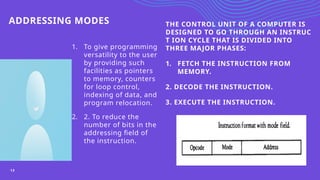
ADDRESSING MODES
1. Togive programming
versatility to the user
by providing such
facilities as pointers
to memory, counters
for loop control,
indexing of data, and
program relocation.
2. 2. To reduce the
number of bits in the
addressing field of
the instruction.
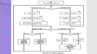
THE CONTROL UNIT OF A COMPUTER IS
DESIGNED TO GO THROUGH AN INSTRUC
T ION CYCLE THAT IS DIVIDED INTO
THREE MAJOR PHASES:
1. FETCH THE INSTRUCTION FROM
MEMORY.
2. DECODE THE INSTRUCTION.
3. EXECUTE THE INSTRUCTION.
13
14.
VARIOUS ADDRESSING
MODES
Immediate Mode:In this mode the operand is specified in the instruction itself.
Register Mode: In this mode the operands are in registers that reside within the CPU.
Register Indirect Mode: In this mode the instruction specifies a register in the CPU whose contents give
the address of the operand in memory.
Autoincrement or Autodecrement Mode: This is similar to the register in d i rect mode except that the
register is incremented or decremented after (or before) its value is used to access memory.
Direct Address Mode: In this mode the effective address is equal to the address part of the instruction.
Indirect Address Mode: In this mode the address field of the instruction gives the address where the
effective address is stored in memory.
Relative Address Mode: In this mode the content of the program counter is added to the address part of
the instruction in order to obtain the effective address.
Indexed Addressing Mode: In this mode the content of an index register is added to the address part of
the instruction to obtain the effective address.
14
15.
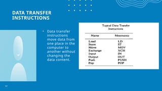
DATA TRANSFER
INSTRUCTIONS
• Datatransfer
instructions
move data from
one place in the
computer to
another without
changing the
data content.
15
DATA TRANSFER
INSTRUCTIONS
• Datatransfer
instructions
move data from
one place in the
computer to
another without
changing the
data content.
17
18.
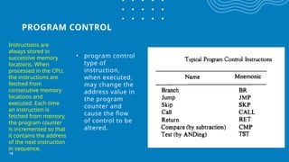
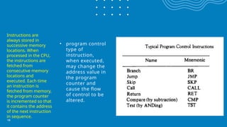
PROGRAM CONTROL
• programcontrol
type of
instruction,
when executed,
may change the
address value in
the program
counter and
cause the flow
of control to be
altered.
18
Instructions are
always stored in
successive memory
locations. When
processed in the CPU,
the instructions are
fetched from
consecutive memory
locations and
executed. Each time
an instruction is
fetched from memory,
the program counter
is incremented so that
it contains the address
of the next instruction
in sequence.
19.
• program control
typeof
instruction,
when executed,
may change the
address value in
the program
counter and
cause the flow
of control to be
altered.
19
Instructions are
always stored in
successive memory
locations. When
processed in the CPU,
the instructions are
fetched from
consecutive memory
locations and
executed. Each time
an instruction is
fetched from memory,
the program counter
is incremented so that
it contains the address
of the next instruction
in sequence.


![SAMPLE INSTRUCTIONS
12
1. ADD R1, R2, R3
2. ADD R1, R2
3. MOV R1, R2
4. ADD R1, A, B R1<-- M[A] + M[B]
5. ADD R2, C, D R2<-- M[C] + M[D]
6. MUL X, R1, R2 M[X] <-- R1•R2
• MOV R1, A R1<--M[A]
• ADD R1, B R1 <-- R1 + M[B]
• MOV R2, C R2<-- M[C]
• ADD R2, D R2<-- R2 + M[D]
• MUL R1,R2 R1 <-- R1• R2
• MOV X, R1 M[X] <-- R1
THREE ADDRESS
INSTRUCTIONS TWO ADDRESS
INSTRUCTIONS
ONE ADDRESS
INSTRUCTIONS
1. LOAD A AC<-M[A]
2. ADD B AC <-AC+M[B]
3. STORE T M[T] <-AC
4. LOAD C AC <-M[C]
5. ADD D AC <-AC+M[D]
6. MUL T AC <-AC*M[T]
7. STORE M[X] <-AC](https://image.slidesharecdn.com/coaunit-ii-250820150100-5e749263/85/computer-organization-and-architecute-unit-2-12-320.jpg)