Pin Description ofI2C Module
• The term I2C stands for “Inter Integrated Circuits”.
• It is normally denoted as IIC or I squared C or even as 2-
wire interface protocol (TWI).
• I2C is a synchronous communication protocol, means both
the devices that are sharing the information must share a
common clock signal.
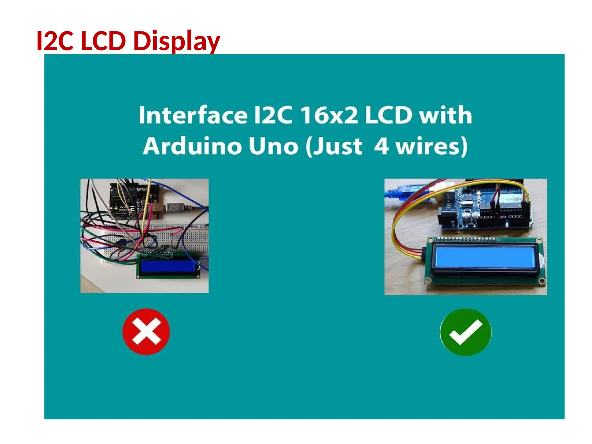
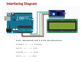
• It has only two wires, SDA (serial data) and SCL to share
information, out of which SCL(serial clock ) is used for the
clock signal and SDA is used for sending and receiving data.
3.
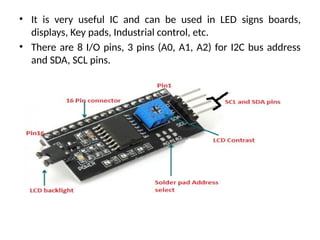
• It isvery useful IC and can be used in LED signs boards,
displays, Key pads, Industrial control, etc.
• There are 8 I/O pins, 3 pins (A0, A1, A2) for I2C bus address
and SDA, SCL pins.
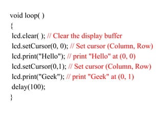
void loop( )
{
lcd.clear(); // Clear the display buffer
lcd.setCursor(0, 0); // Set cursor (Column, Row)
lcd.print("Hello"); // print "Hello" at (0, 0)
lcd.setCursor(0,1); // Set cursor (Column, Row)
lcd.print("Geek"); // print "Geek" at (0, 1)
delay(100);
}
8.
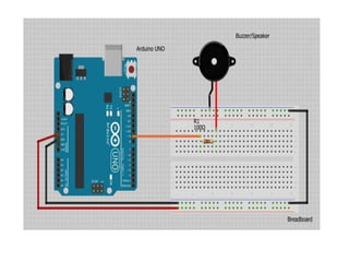
Buzzer with Arduino
•By interfacing a buzzer with Arduino, you can
create sound effects, alarms, melodies, and more.
• Buzzers can be found in alarm devices,
computers, timers and confirmation of user input
such as a mouse click or keystroke.
• converting electronic vibrations into speaker
pulses which vibrate the air.
• Ex: Arduino to play “Twinkle Twinkle Little
Star”
9.
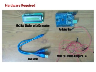
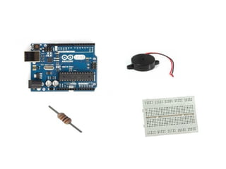
•For this tutorialyou will
need:Arduino uno
•Breadboard
•Buzzer/piezo speaker
•100 Ohm resistor
11.
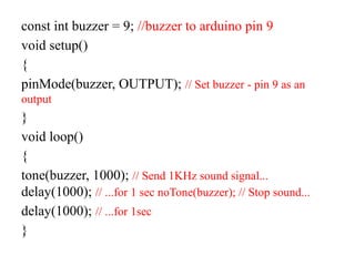
const int buzzer= 9; //buzzer to arduino pin 9
void setup()
{
pinMode(buzzer, OUTPUT); // Set buzzer - pin 9 as an
output
}
void loop()
{
tone(buzzer, 1000); // Send 1KHz sound signal...
delay(1000); // ...for 1 sec noTone(buzzer); // Stop sound...
delay(1000); // ...for 1sec
}
12.
Using Sensors andActuators with
Arduino
Sensors: Sensor is a device used for the
conversion of physical events or characteristics
into the electrical signals. capturing data from
the physical world.
This is a hardware device that takes the input
from environment and gives to the system by
converting it.
13.
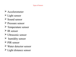
Types of Sensors
Accelerometer
Light sensor
Sound sensor
Pressure sensor
Temperature sensor
IR sensor
Ultrasonic sensor
humidity sensor
PIR sensor
Water detector sensor
Light distance sensor
14.
Actuator: Actuator isa device that converts the
electrical signals into the physical events or
characteristics.
It takes the input from the system and gives
output to the environment.
Ex: motors and heaters
15.
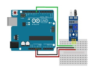
Interfacing IR SensorModule with Arduino
An infrared proximity sensor or IR Sensor is
an electronic device that emits infrared lights to
sense some aspect of the surroundings and can
be employed to detect the motion of an object.
This sensor is very common in the electronic
industry and if you’ve ever tried to design an
obstacle avoidance robot or any other
proximity detection-based system.
16.
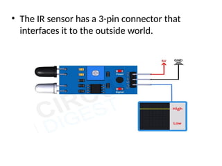
• The IRsensor has a 3-pin connector that
interfaces it to the outside world.
18.
• The workingof the IR sensor module is very
simple, it consists of two main components:
the first is the IR transmitter section and the
second is the IR receiver section. In the
transmitter section, IR led is used and in the
receiver section, a photodiode is used to
receive infrared signal and after some signal
processing and conditioning, you will get the
output.
19.
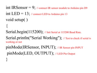
int IRSensor =9; // connect IR sensor module to Arduino pin D9
int LED = 13; // connect LED to Arduino pin 13
void setup( )
{
Serial.begin(115200); // Init Serial at 115200 Baud Rate.
Serial.println("Serial Working"); // Test to check if serial is
working or not
pinMode(IRSensor, INPUT); // IR Sensor pin INPUT
pinMode(LED, OUTPUT); // LED Pin Output
}
20.
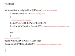
void loop( )
{
intsensorStatus = digitalRead(IRSensor); // Set the GPIO as Input
if (sensorStatus == 1) // Check if the pin high or not
{
// if the pin is high turn off the onboard Led
digitalWrite(LED, LOW); // LED LOW
Serial.println("Motion Detected!"); // print Motion Detected! on the serial monitor window
}
else
{
//else turn on the onboard LED
digitalWrite(LED, HIGH); // LED High
Serial.println("Motion Ended!"); // print Motion Ended! on the serial monitor window
}
}
21.
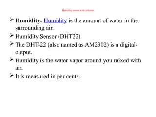
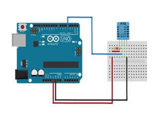
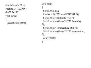
Humidity sensor withArduino
Humidity: Humidity is the amount of water in the
surrounding air.
Humidity Sensor (DHT22)
The DHT-22 (also named as AM2302) is a digital-
output.
Humidity is the water vapor around you mixed with
air.
It is measured in per cents.
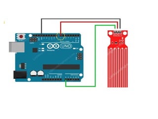
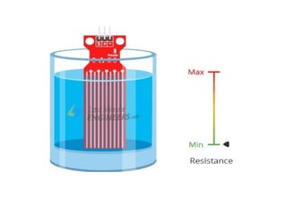
Water Level SensorInterface with Arduino
Water Level Sensor measure the water
level(detect the presence of water.)
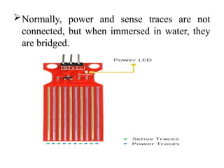
The Water Level Sensor has ten exposed
copper traces.
five of which are power traces and the
remaining five are sense traces.
These traces are interlaced so that there is one
sense trace between every two power traces.
25.
Normally, power andsense traces are not
connected, but when immersed in water, they
are bridged.
28.
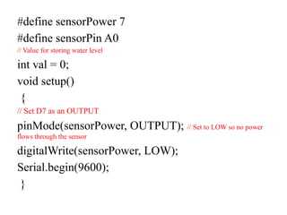
#define sensorPower 7
#definesensorPin A0
// Value for storing water level
int val = 0;
void setup()
{
// Set D7 as an OUTPUT
pinMode(sensorPower, OUTPUT); // Set to LOW so no power
flows through the sensor
digitalWrite(sensorPower, LOW);
Serial.begin(9600);
}
29.
void loop()
{
//get thereading from the function below and print it
Int level = readSensor();
Serial.print("Water level: ");
Serial.println(level);
delay(1000); }
//This is a function used to get the reading
int readSensor()
{
digitalWrite(sensorPower, HIGH);
// Turn the sensor ON
delay(10); // wait 10 milliseconds
val = analogRead(sensorPin); // Read the analog value form sensor
digitalWrite(sensorPower, LOW); // Turn the sensor OFF
return val; // send current reading
}
30.
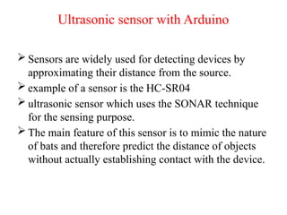
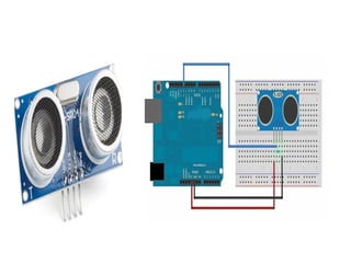
Ultrasonic sensor withArduino
Sensors are widely used for detecting devices by
approximating their distance from the source.
example of a sensor is the HC-SR04
ultrasonic sensor which uses the SONAR technique
for the sensing purpose.
The main feature of this sensor is to mimic the nature
of bats and therefore predict the distance of objects
without actually establishing contact with the device.
31.
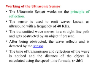
Working of theUltrasonic Sensor
• The Ultrasonic Sensor works on the principle of
reflection.
• The sensor is used to emit waves known as
ultrasound with a frequency of 40 KHz.
• The transmitted wave moves in a straight line path
and gets obstructed by an object if present.
• After being obstructed, the wave reflects and is
detected by the sensor.
• The time of transmission and reflection of the wave
is noticed and the distance of the object is
calculated using the speed-time formula. s= 2d/t
32.
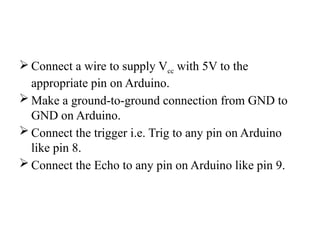
Connect awire to supply Vcc with 5V to the
appropriate pin on Arduino.
Make a ground-to-ground connection from GND to
GND on Arduino.
Connect the trigger i.e. Trig to any pin on Arduino
like pin 8.
Connect the Echo to any pin on Arduino like pin 9.
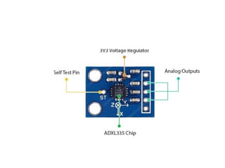
Accelerometer Interface withArduino
Accelerometers is the device capable of detecting
changes in motion in the form of acceleration.
It can also measure the vibration of the structure.
Accelerometers are widely used in low-power, low-cost
motion and tilt sensing applications such as mobile
devices, gaming systems, disk drive protection, image
stabilization, and sports and health devices.
Ex: ADXL320, ADXL321, ADXL322, ADXL330
It can measure not only static acceleration caused by
gravity, but also dynamic acceleration caused by
motion, shock, or vibration.
39.
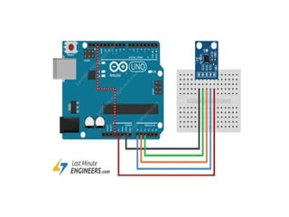
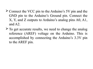
Connect theVCC pin to the Arduino’s 5V pin and the
GND pin to the Arduino’s Ground pin. Connect the
X, Y, and Z outputs to Arduino’s analog pins A0, A1,
and A2.
To get accurate results, we need to change the analog
reference (AREF) voltage on the Arduino. This is
accomplished by connecting the Arduino’s 3.3V pin
to the AREF pin.
40.
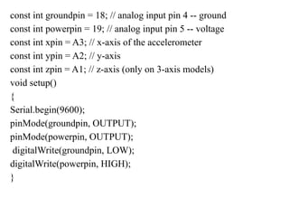
const int groundpin= 18; // analog input pin 4 -- ground
const int powerpin = 19; // analog input pin 5 -- voltage
const int xpin = A3; // x-axis of the accelerometer
const int ypin = A2; // y-axis
const int zpin = A1; // z-axis (only on 3-axis models)
void setup()
{
Serial.begin(9600);
pinMode(groundpin, OUTPUT);
pinMode(powerpin, OUTPUT);
digitalWrite(groundpin, LOW);
digitalWrite(powerpin, HIGH);
}
41.
void loop() {
//print the sensor values:
Serial.print(analogRead(xpin));
// print a tab between values:
Serial.print("t");
Serial.print(analogRead(ypin));
// print a tab between values:
Serial.print("t");
Serial.print(analogRead(zpin));
Serial.println();
// delay before next reading:
delay(100);
}
42.
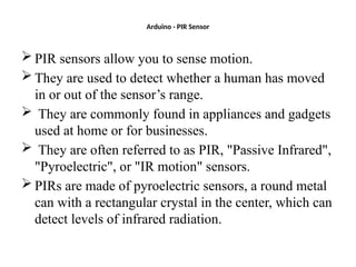
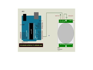
Arduino - PIRSensor
PIR sensors allow you to sense motion.
They are used to detect whether a human has moved
in or out of the sensor’s range.
They are commonly found in appliances and gadgets
used at home or for businesses.
They are often referred to as PIR, "Passive Infrared",
"Pyroelectric", or "IR motion" sensors.
PIRs are made of pyroelectric sensors, a round metal
can with a rectangular crystal in the center, which can
detect levels of infrared radiation.
44.
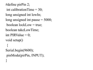
#define pirPin 2;
intcalibrationTime = 30;
long unsigned int lowIn;
long unsigned int pause = 5000;
boolean lockLow = true;
boolean takeLowTime;
int PIRValue = 0;
void setup()
{
Serial.begin(9600);
pinMode(pirPin, INPUT);
}