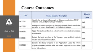
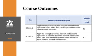
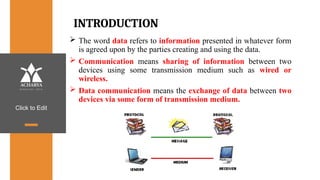
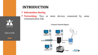
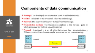
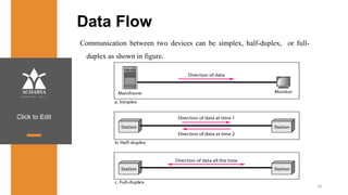
w w w . a c h a r y a . a c . i n
Click to Edit
Overveiw
Acharya stands as a beacon of excellence in higher education,
boasting a legacy of academic distinction since its establishment in
1990. We offer a transformative educational experience, fostering
holistic development, nurturing innovation and providing world-
class facilities to ensure an enriching journey for our students.
Dept of ECE
Click to Edit
Prepared by:
SNEHA N P
Assistant Professor
Dept.of Computer Science &
Engineering
AIT
COMPUTER NETWORKS
BCS502
3
Module-1
Click to Edit
Overview of Syllabus
Module 1
• Introduction: Data Communications, Networks, Network Types,
Networks Models: Protocol Layering, TCP/IP Protocol suite, The
OSI model, Introduction to Physical Layer: Transmission media,
Guided Media, Unguided Media: Wireless. Switching: Packet
Switching and its types.
• Textbook: Ch. 1.1 - 1.3, 2.1 - 2.3, 7.1 – 7.3, 8.3
Click to Edit
Overview of Syllabus
Module 2
• Data Link Layer: Error Detection and Correction: Introduction,
Block Coding, Cyclic Codes. Data link control: DLC Services:
Framing, Flow Control, Error Control, Connectionless and
Connection Oriented, Data link layer protocols, High Level Data
Link Control. Media Access Control: Random Access, Controlled
Access. Check Sum and Point to Point Protocol
• Textbook: Ch. 10.1-10.4, 11.1 -11.4, 12.1 - 12.2
Click to Edit
Overview of Syllabus
Module 3
• Network Layer: Network layer Services, Packet Switching, IPv4
Address, IPv4 Datagram, IPv6 Datagram, Introduction to Routing
Algorithms, Unicast Routing Protocols: DVR, LSR, PVR,
• Unicast Routing protocols: RIP, OSPF, BGP, Multicasting Routing-
MOSPF
• Textbook: Ch. 18.1, 18.2, 18.4, 22.2,20.1-20.3, 21.3.2
Click to Edit
Overview of Syllabus
Module 4
• Introduction to Transport Layer: Introduction, Transport-Layer
Protocols: Introduction, User Datagram Protocol, Transmission
Control Protocol: services, features, segments, TCP connections,
flow control, Error control, Congestion control.
• Textbook: Ch. 23.1- 23.2, 24.1-24.3.4, 24.3.6-24.3.9
Click to Edit
Overview of Syllabus
Module 5
• Introduction to Application Layer: Introduction, Client-Server
Programming, Standard Client-Server Protocols: World Wide Web
and HTTP, FTP, Electronic Mail, Domain Name System (DNS),
TELNET, Secure Shell (SSH)
• Textbook: Ch. 25.1-25.2, 26.1-26.6
Click to Edit
Textbooks
1. Behrouz A. Forouzan, Data Communications and Networking
5E, 5th Edition, Tata McGraw-Hill,2013.
Reference Books:
2. William Stallings: Data and Computer Communication, 8th
Edition, Pearson Education, 2007.
3. Larry L. Peterson and Bruce S. Davie: Computer Networks – A
Systems Approach, 4th Edition, Elsevier, 2007.
4. Nader F. Mir: Computer and Communication Networks, Pearson
Education, 2007.
Click to Edit
Course Objectives
This course will enable students to,
1. Study the TCP/IP protocol suite, switching criteria and Medium
Access Control protocols for reliable and noisy channels.
2. Learn network layer services and IP versions.
3. Discuss transport layer services and understand UDP and TCP
protocols.
4. Demonstrate the working of different concepts of networking
layers and protocols.
Click to Edit
Course Outcomes
Cos Course outcome Description
Blooms
Level
BCS502.1
Explain the fundamental concepts of data communication, TCP/IP
Protocol suite, and physical layer functions. BL2
BCS502.2
Apply error detection and correction techniques in data transmission
scenarios to ensure data integrity at the Data Link Layer. BL3
BCS502.3
Apply the routing protocols in network environments to ensure data
transmission.
BL2
BCS502.4
Explain the basic functions of the Transport Layer and their roles in
reliable network communication.
BL2
BCS502.5
Describe the basic concepts of the Application Layer, the role it
plays in network communication and how it supports various client-
server interactions.
BL2
Click to Edit
Course Outcomes
Cos Course outcome Description
Blooms
Level
BCS502.6
Implement a three-node point-to-point network under
different configurations demonstrating an understanding
of network performance. BL3
BCS502.7
Apply the concepts of various network protocols and
algorithms, to simulate real-world network scenarios to
assess their effectiveness in efficient data transmission
across different network environments.
BL3
Click to Edit
INTRODUCTION
 The word data refers to information presented in whatever form
is agreed upon by the parties creating and using the data.
 Communication means sharing of information between two
devices using some transmission medium such as wired or
wireless.
 Data communication means the exchange of data between two
devices via some form of transmission medium.
Click to Edit
INTRODUCTION
 Information sharing
 Networking: Two or more devices connected by some
communication link.
Click to Edit
Components of data communication
Message : The message is the information (data) to be communicated .
Sender: The sender is the device that sends the data message.
Receiver :The receiver is the device that receives the message.
Transmission medium :The transmission medium is the physical path by
which a message travels from sender to receiver.
Protocol : A protocol is a set of rules that govern data communications .
Without a protocol, two devices may be connected but not communicating.
15
Click to Edit
Characteristics of data communication system
 Delivery : The system must deliver data to the correct destination .
 Accuracy :The system must deliver the data accurately.
 Timeliness: The system must deliver data in a timely manner.
 Real time transmission : Delivering data as they are produced, in the same order
that they are produced, and without significant delay.
 Jitter: Jitter refers to variation in the packet arrival time.
 Video packets are sent every 30 ms . If some of the packets arrive with 30-ms
delay and others with 40-ms delay, an uneven quality in the video is the result.
16
Click to Edit
Data Representation
 Text: It is represented as a bit pattern, a sequence of bits(0s or 1s). Each set is
called a code, and the process of representing symbols is called coding.
 Numbers: It is also represented by bit patterns .
 Images: An image is composed of a matrix of pixels where each pixel is a small
dot . After an image is divided into pixels, each pixel is assigned a bit pattern.
 Audio: It refers to the recording or broadcasting of sound or music. It is
continuous, not discrete.
 Video: Video refers to the recording or broadcasting of a picture or
movie. It can be continuous or discrete.
17
Click to Edit
Data Flow
Communication between two devices can be simplex, half-duplex, or full-
duplex as shown in figure.
18
Click to Edit
 Simplex: Communication is unidirectional, Only one of the two
devices on a link can transmit; the other can only receive.
E.g. : One way street, Keyboard , Monitor.
 Half duplex: Each station can both transmit and receive, but not at
the same time. When one device is sending, the other can only
receive, and vice versa.
E.g.: Walkie Talkie.
 Full duplex: Both stations can transmit and receive simultaneously.
It is like a two way street with the traffic flowing in both the
directions at the same time.
E.g .: Telephone network
19
Click to Edit
Networks
Networks : A network is a set of devices (nodes) connected by
communication links. A node can be a computer, printer, or any other
device capable of sending and/or receiving data generated by other
nodes on the network.
A link can be a cable, air, optical fiber, or any medium which can
transport a signal carrying information.
Distributed Processing : Here task is divided among multiple
computers. Instead of one single large machine being responsible for all
aspects of a process, separate computers handle a subset.
20
Click to Edit
Network Criteria
 Performance : It can be measured in two ways.
1. Transit time : It is the amount of time required for a message to travel
from one device to another.
2. Response time : It is the time elapsed between an inquiry and
a response.
 Reliability : It is measured by the frequency of failure, the time it takes
a link to recover from failure.
 Security : It includes protecting data from unauthorized access,
protecting data from damage , implementing policies and procedures for
recovery from data losses.
21
Click to Edit
Physical Structures- Type of Connection
 Point to Point :
 It provides a dedicated link between two devices .
 The entire capacity of the link is reserved for transmission between
those two devices.
 It uses an actual length of wire or cable to connect the two ends.
22
Click to Edit
Physical Structures- Type of Connection
 Multi Point :
 It is the one in which more than two specific devices share a single link.
 Capacity of the channel is either spatially or temporally shared.
 Spatially shared : Several devices can use the link simultaneously.
 Temporally shared : Users take turns.
23
Click to Edit
Physical Topology
 Two or more devices connect to a link; two or more links form a topology.
 Topology : It is the geometric representation of relationship of all the links
and linking devices to one another.
 Four basic topologies :
24
Click to Edit
Mesh Topology
 Every device has a dedicated point-to point link to every
other device.
 The term dedicated means that the link carries traffic only between the
two devices it connects.
 To find the number of physical links in a fully connected mesh
network with n nodes, n(n - 1) / 2 duplex mode links
25
Click to Edit
Advantages :
 A mesh topology is robust. If one link becomes unusable, it does
not incapacitate the entire system.
 Point-to-point links make fault identification and fault isolation
easy.
 Privacy or security : When every message travels along a dedicated
line, only the intended recipient sees it.
Disadvantages :
 Installation and reconnection are difficult.
 The hardware required to connect each link can be
prohibitively expensive.
 The sheer bulk of the wiring can be greater than the available
space can accommodate.
26
Click to Edit
Star Topology
 Each device has a dedicated point-to point link only to a
central controller, usually called a hub.
 The controller acts as an exchange:If one device wants to send data to another,
it sends the data to the controller, which then relays the data to the other
connected device.
27
Click to Edit
Advantages:
 A star topology is less expensive than a mesh topology. Each device
needs only one link and one I/O port to connect it to any number of
others.
 Easy to install and reconfigure.
 Requires less cabling, less expensive than mesh topology.
 Robustness: If one link fails, only that link is affected. All other
links remain active. As a result fault identification and fault
isolation becomes easy.
Disadvantages :
 Dependency of whole topology on one single point, the hub.
E.g. : LAN
28
Click to Edit
Bus Topology
 One long cable acts as a backbone to link all the devices in a
network.
 Nodes are connected to the bus cable by drop lines and taps.
 A drop line is a connection running between the device and the main
cable.
 As a signal travels along the backbone,
some of its energy is transformed into heat.
 As a result there is a limit on the number of taps a bus can support and on
the distance between those taps.
29
Click to Edit
30
Advantages:
 Ease of installation : Backbone cable can be laid along the most efficient
path, then connected to the nodes and drop lines.
 Signal reflection at the taps can cause degradation in quality. This
degradation can be controlled by limiting the number and spacing of
devices connected to a given length of cable.
Disadvantages :
 A bus is usually designed to be optimally efficient at installation. It can
therefore be difficult to add new devices.
 A fault or break in the bus cable stops all transmission, and the damaged
area reflects signals back in the direction of origin, creating noise in both
directions.
 Adding new devices may therefore require modification or replacement
of the backbone.
Click to Edit
Ring Topology
 Each device has a dedicated point-to-point connection with only the two
devices on either side of it.
 A signal is passed along the ring in one direction, from device to device,
until it reaches its destination.
 Each device in the ring incorporates a repeater.
 When a device receives a signal intended for another device, its repeater
regenerates the bits and passes them along.
31
Click to Edit
32
Advantages :
 A ring is relatively easy to install and
reconfigure. Each device is linked to only its immediate
neighbors.
 To add or delete a device requires changing only two
connections.
 Fault isolation is simplified. Here, a signal is circulating at all
times. If one device does not receive a signal within a specified
period, it can issue an alarm.
 The alarm alerts the network operator to the problem and its
location.
Disadvantages :
 Unidirectional traffic can be a disadvantage.
 In a simple ring, a break in the ring can disable the entire
network.
Click to Edit
Hybrid Topology
33
Click to Edit
Network Models
 Local Area Networks (LAN): It is privately owned and
links the devices in a single office, building, or campus.
 LAN can be as simple as two PCs and a printer in someone's home
office . Its size is limited to a few kilometers.
 LANs are designed to allow resources to be shared between personal
computers or workstations.
 The resources to be shared can include hardware (e.g., a printer), software
(e.g., an application program).
34
Click to Edit
Click to Edit
Network Models
Wide Area Networks (WAN):
 It provides long-distance transmission of data, image, audio, and
video information over large geographic areas that comprise a country,
a continent or even the whole world.
Two types of WAN:
 Point to Point WAN : A point-to-point WAN is a network that
connects two communicating devices through a transmission media
(cable or air).
 The switched WAN : It connects the end systems, which usually
comprise a router that connects to another LAN or WAN.
36
Click to Edit
Click to Edit
Switching
An internet is a switched network in which a switch connects at least two links
together. A switch needs to forward data from a network to another .
Two types of switched networks :
 Packet Switched networks : Here communication between the two ends is
done in blocks of data called packets.
 Router has a queue that can store and forward the packet which is used for
longer distance transmission.
38
Click to Edit
39
 Circuit Switched networks : Here a dedicated connection called a
circuit is available between two end systems.
 Switches are used to connect end system within a network.
 The thick line connecting two switches is a high capacity
communication line that can handle four voice communication at the
same time.
Click to Edit
Internetwork
40
Click to Edit
Internetwork
Click to Edit
The Internet
 Backbone networks are large networks owned by companies like
Sprint , Verizon , AT&T and NTT. They are connected through peering
points.
 Provider networks are smaller networks uses the services of the
backbones for a fee.
 Customer networks that actually use the services provided by the
internet.
42
Click to Edit
43
Click to Edit
Accessing the Internet
Using Telephone Networks
 Dial up Service : To the telephone line add a modem that converts data to
voice. But it is very slow when line used for internet connection.
 DSL Service : Telephone companies have upgraded their telephone lines
to provide higher speed internet services .
Using Cable Networks
 The cable companies have been upgrading their cable
networks to provide internet connection.
 But speed varies depending on the number of neighbors that use the
same cable.
Using Wireless Networks
 A household or small business can be connected to the internet through a
wireless LAN.
Direct Connection to the internet : A large organization can become a local
ISP and be connected to internet.
44
Click to Edit
Network Models
PROTOCOL LAYERING
Protocol defines the rules that both the sender and receiver and all
intermediate devices need to follow to be able to communicate effectively.
When communication is simple- one simple protocol
When the communication is complex-need to divide the task between
different layers, in which case we need a protocol at each layer, or protocol
layering.
Chapter 2
Click to Edit
Scenarios
Let us develop two simple scenarios to better understand the need for protocol layering.
First scenario
 communication is so simple that it can occur in only one layer.
 Assume Maria and Ann are neighbors with a lot of common ideas.
 Communication between Maria and Ann takes place in one layer, face to face, in the
same language, as shown in Figure.
Click to Edit
2.42
Even in this simple scenario, we can see that a set of rules needs to be followed.
1.Maria and Ann know that they should greet each other when they meet.
2.They know that they should confine their vocabulary to the level of their friendship.
3.Each party knows that she should refrain from speaking when the other party is
speaking.
4.Each party knows that the conversation should be a dialog, not a monolog: both
should have the opportunity to talk about the issue.
5.They should exchange some nice words when they leave.
Click to Edit
Second Scenario
 Assume that Ann is offered a higher-level position in her company, but needs to move
to another branch located in a city very far from Maria.
 The two friends still want to continue their communication and exchange ideas because
they have come up with an innovative project to start a new business when they both
retire.
 They decide to continue their conversation using regular mail through the post office.
 They do not want their ideas to be revealed by other people if the letters are intercepted.
They agree on an encryption/decryption technique.
Click to Edit
The sender of the letter encrypts it to make it unreadable by an intruder ;
the receiver of the letter decrypts it to get the original letter.
 Now we can say that the communication between Maria and Ann takes place in
three layers, as shown in Figure 2.2.
Click to Edit
Let us assume that Maria sends the first letter to Ann.
At Maria side:
• Maria talks to the machine at the third layer as though the machine is Ann and is
listening to her.
• The third layer machine listens to what Maria says and creates the plaintext (a
letter in English), which is passed to the second layer machine.
• The second layer machine takes the plaintext, encrypts it, and creates the
ciphertext, which is passed to the first layer machine.
• The first layer machine, presumably a robot, takes the ciphertext , puts it in an
envelope, adds the sender and receiver addresses, and mails it.
Click to Edit
At Ann’s side
•The first layer machine picks up the letter from Ann’s mail box, recognizing the letter
from Maria by the sender address.
•The machine takes out the ciphertext from the envelope and delivers it to the second
layer machine.
•The second layer machine decrypts the message, creates the plaintext, and passes the
plaintext to the third-layer machine.
•The third layer machine takes the plaintext and reads it as though Maria is speaking.
Protocol layering enables us to divide a complex task into several smaller and simpler
tasks.
Click to Edit
 For example, in Figure 2.2, we could have used only one machine to do the job of
all three machines. However, if Maria and Ann decide that the encryption/
decryption done by the machine is not enough to protect their secrecy, they
would have to change the whole machine.
 In the present situation, they need to change only the second layer machine; the
other two can remain the same. This is referred to as modularity.
 Modularity in this case means independent layers.
 A layer (module) can be defined as a black box with inputs and outputs, without
concern about how inputs are changed to outputs.
 If two machines provide the same outputs when given the same inputs, they can
replace each other.
Click to Edit
 For example, Ann and Maria can buy the second layer machine from two different
manufacturers. As long as the two machines create the same ciphertext from the same
plaintext and vice versa, they do the job.
Advantages of protocol layering
 Allows to separate the services from the implementation.
• A layer needs to be able to receive a set of services from the lower layer
and to give the services to the upper layer; we don’t care about how the layer is
implemented.
• For example, Maria may decide not to buy the machine (robot) for the first
layer; she can do the job herself. As long as Maria can do the tasks provided by
the first layer, in both directions, the communication system works.
Click to Edit
 Reduces the complexity at the intermediate system
• Communication does not always use only two end systems; there are intermediate
systems that need only some layers, but not all layers.
• If we did not use protocol layering, we would have to make each intermediate system
as complex as the end systems, which makes the whole system more expensive.
Two principles of protocol layering
First Principle
 The first principle dictates that if we want bidirectional communication, we need to
make each layer so that it is able to perform two opposite tasks, one in each direction.
 For example, the third layer task is to listen (in one direction) and talk (in the other
direction). The second layer needs to be able to encrypt and decrypt. The first layer needs
to send and receive mail.
Click to Edit
Second Principle
The second principle that we need to follow in protocol layering is that the two
objects under each layer at both sites should be identical.
 For example, the object under layer 3 at both sites should be a
plaintext letter. The object under layer 2 at both sites should be a ciphertext letter.
The object under layer 1 at both sites should be a piece of mail.
Logical Connections
 Two protocols at the same layer can have a logical Connection
 This means that we have layer-to-layer communication.
Click to Edit
Maria and Ann can think that there is a logical (imaginary) connection at each
layer through which they can send the object created from that layer.
Click to Edit
TCP/IP PROTOCOL SUITE
 TCP/IP(Transmission Control Protocol/Internet Protocol) suite used in
the Internet today.
 It is a hierarchical protocol made up of interactive modules, each of
which provides a specific functionality.
hierarchical means that each upper level protocol
is
by the services provided by one or more lower
level
 The term
supported
protocols.
 The original TCP/IP protocol suite was defined as four software layers
built upon the hardware.
 Today, however, TCP/IP is thought of as a five-layer model. Figure 2.4
shows both configurations.
Click to Edit
Layered Architecture
 To show how the layers in the TCP/IP protocol suite are involved in
communication between two hosts, we assume that we want to use the suite
in a small internet made up of three LANs (links), each with a link- layer switch.
 We also assume that the links are connected by one router
Click to Edit
Click to Edit
 Let us assume that computer A communicates with computer B.
 As the figure shows, we have five communicating devices in this
communication:
1.source host(computer A)
2.The link-layer switch in link 1
3.The router
4.The link-layer switch in link 2,
5.destination host (computer B).
 Each device is involved with a set of layers depending on the role of the
device in the internet.
 The two hosts are involved in all five layers
 The source host needs to create a message in the application layer and
send it down the layers so that it is physically sent to the destination host.
 The destination host needs to receive the communication at the physical
layer and then deliver it through the other layers to the application layer.
Click to Edit
 The router is involved in only three layers; link-layer switch in a link is involved
only in two layers, data-link and physical.
Layers in the TCP/IP Protocol Suite
 To better understand the duties of each layer, we need to think about the logical
connections between layers.
Click to Edit
 The duty of the application, transport, and network layers is end-to-
end.
 The duty of the data-link and physical layers is hop-to-hop, in which a
hop is a host or router.
 The domain of duty of the top three layers is the internet, and the
domain of duty of the two lower layers is the link.
 Another way of thinking of the logical connections is to think about the
data unit created from each layer.
 In the top three layers, the data unit (packets) should not be changed
by any router or link-layer switch.
 In the bottom two layers, the packet created by the host is changed
only by the routers, not by the link-layer switches.
Click to Edit
 Figure 2.7 shows the second principle the identical objects at each layer
related to each device.
 Although the logical connection at the network layer is between the two
hosts, we can only say that identical objects exist between two hops in this case
because a router may fragment the packet at the network layer and send more
packets than Received.
Click to Edit
Description of Each Layer
Physical Layer
The lowest level in the TCP/IP protocol suite, responsible for carrying
individual bits in a frame across the link
Two devices are connected by a transmission medium (cable or air).
The transmission medium does not carry bits; it carries electrical or
optical signals.
So the bits received in a frame from the data-link layer are transformed
and sent through the transmission media
Click to Edit
Data-link Layer
 Responsible for taking the datagram and moving it across the link.
 Internet is made up of several links (LANs and WANs) connected by routers.
 The routers are responsible for choosing the best links when the next link
to travel is determined by the router, the data-link layer is responsible for
taking the datagram and moving it across the link.
 The link can be a wired LAN with a link-layer switch, a wireless LAN, a wired
WAN, or a wireless WAN.
 TCP/IP does not define any specific protocol for the data-link layer. It supports
all the standard and proprietary protocols.
 The data-link layer takes a datagram and encapsulates it in a packet called a
frame.
 Each link-layer protocol may provide a different service. Some link-layer
protocols provide complete error detection and correction, some provide
only error correction
Click to Edit
Network Layer
responsible for creating a connection between the source computer and the
destination computer.
Responsible for host-to-host communication and routing the packet through
possible routes.
The network layer in the Internet includes the main protocol, Internet Protocol
(IP),
• Defines the format of the packet, called a datagram at the network layer.
• defines the format and the structure of addresses used in this layer.
• responsible for routing a packet from its source to its
destination, which is achieved by each router forwarding the datagram to
the next router in its path.
IP is a connectionless protocol.
It provides no flow control, no error control, and no congestion control
services.
Click to Edit
 The network layer also includes unicast (one-to-one) and
multicast (one-to-many) routing protocols.
 A routing protocol does not take part in but it creates forwarding
tables for routers to help them in the routing process.
 The network layer also has some auxiliary protocols that help IP in its
delivery and routing tasks.
• The Internet Control Message Protocol (ICMP)
• The Dynamic Host Configuration Protocol (DHCP)-helps IP to get
the network-layer address for a host.
• The Address Resolution Protocol (ARP)
Click to Edit
Transport Layer
Responsible for giving services to the application layer: to get a
message from an application program running on the source host
encapsulates it in a transport layer packet (called a segment or a user
datagram and deliver it to the corresponding application program on
the destination host through the logical connection
The logical connection at the transport layer is also end-to-end.
There are a few transport-layer protocols in the Internet, each
designed for some specific task.
Transmission Control Protocol (TCP)
• connection-oriented protocol that first establishes a logical
connection between transport layers at two hosts before
transferring data.
• provides flow control, error control and congestion.
Click to Edit
control
User Datagram Protocol (UDP)
• Connectionless protocol that transmits user datagrams without
first
creating a logical connection
• each user datagram is an independent entity without being related to
the previous or the next one
• does not provide flow, error, or congestion control
• simplicity, which means small overhead, is attractive to an application
program that needs to send short messages and cannot afford the
retransmission of the packets involved in TCP, when a packet is corrupted
or lost.
Stream Control Transmission Protocol (SCTP)
• designed to respond to new applications that are emerging in the
multimedia.
Click to Edit
Application Layer
 The logical connection between the two application layers is end to-
end.
 The two application layers exchange messages between each other
as though there were a bridge between the two layers.
 Communication at the application layer is between two processes
(two programs running at this layer).
 To communicate, a process sends a request to the other process
and receives a response.
 Process-to-process communication is the duty of the application
layer.
 The application layer in the Internet includes many predefined
protocols, but a user can also create a pair of processes to be run at
the two hosts.
 The Hypertext Transfer Protocol (HTTP) : accessing the World Wide
Web (WWW).
Click to Edit
 The Simple Mail Transfer Protocol (SMTP): e-mail service.
 The File Transfer Protocol (FTP): File Transfer.
 The Terminal Network (TELNET) and Secure Shell (SSH): Remote
login
Protocol (SNMP): to manage the
 The Simple Network Management
Internet at global and local levels.
 The Domain Name System (DNS): to find the network-layer address of
a computer.
 The Internet Group Management Protocol (IGMP): to
collect membership in a group.
Click to Edit
Encapsulation and Decapsulation
Click to Edit
Encapsulation at the Source Host
1. At the application layer, the data to be exchanged is referred to as
a message. It does not contain header or trailer and message is
passed to transport layer.
2. The transport layer takes the message as the payload, the load that
the transport layer should take care of. It adds the transport layer
header to the payload, which contains the identifiers of the source
and destination application programs plus some more information
that is needed for the end-to end delivery of the message, such as
information needed for flow, error control, or congestion control.
The result is the transport-layer packet, which is called the
segment(in TCP) and the user datagram (in UDP). The transport
layer then passes the packet to the network layer.
Click to Edit
3. The network layer takes the transport-layer packet as data or
payload and adds its own header to the payload. The header
contains the addresses of the source and destination hosts and
some more information used for error checking of the header,
fragmentation information, and so on. The result is the network-
layer packet, called a datagram. The network layer then passes the
packet to the data-link layer.
4. The data-link layer takes the network-layer packet as data or
payload and adds its own header, which contains the link-layer
addresses of the host or the next hop (the router). The result is the
link-layer packet, which is called a frame. The frame is passed to the
physical layer for transmission.
Click to Edit
Decapsulation and Encapsulation at the Router
 At the router, we have both decapsulation and encapsulation
because the router is connected to two or more links.
1. After the set of bits are delivered to the data-link layer, this layer
decapsulates the datagram from the frame and passes it to the
network layer.
2. The network layer only inspects the source and destination
addresses in the datagram header and consults its forwarding table
to find the next hop to which the datagram is to be delivered. The
contents of the datagram should not be changed by the network
layer in the router unless there is a need to fragment the datagram
if it is too big to be passed through the next link. The datagram is
then passed to the data-link layer of the next link.
3. The data-link layer of the next link encapsulates the datagram in a
frame and passes it to the physical layer for transmission.
Click to Edit
Decapsulation at the Destination Host
 At the destination host, each layer only decapsulates the packet
received, removes the payload, and delivers the payload to the next-
higher layer protocol until the message reaches the application layer.
 decapsulation in the host involves error checking.
Addressing
 we have logical communication between pairs of layers in this model.
 Any communication that involves two parties needs two addresses:
source address and destination address.
 Although it looks as if we need five pairs of addresses, one pair per
layer, we normally have only four because the physical layer does not
need addresses; the unit of data exchange at the physical layer is a bit,
which definitely cannot have an address.
Click to Edit
 There is a relationship between the layer, the address used in that
layer, and the packet name at that layer.
 At the application layer, we normally use names to define the site that
provides services, such as someorg.com,or the e-mail address, such
as somebody@coldmail.com.
Click to Edit
 At the transport layer, addresses are called port numbers, and these
define the application-layer programs at the source and destination.
 Port numbers are local addresses that distinguish between several
programs running at the same time.
 At the network-layer, the addresses are global, with the whole Internet
as the scope.
 A network-layer address uniquely defines the connection of a device to
the Internet.
 The link-layer addresses, sometimes called MAC addresses, are locally
defined addresses, each of which defines a specific host or router in a
network (LAN or WAN).
Click to Edit
Multiplexing and Demultiplexing
 Since the TCP/IP protocol suite uses several protocols at some layers,
we can say that we have multiplexing at the source and
demultiplexing at the destination.
 Multiplexing in this case means that a protocol at a layer can
encapsulate a packet from several next-higher layer protocols (one at
a time)
 Demultiplexing means that a protocol can decapsulate and deliver a
packet to several next-higher layer protocols (one at a time).
Click to Edit
 To be able to multiplex and demultiplex, a protocol needs to have a field
in its header to identify to which protocol the encapsulated packets
belong.
 At the transport layer, either UDP or TCP can accept a message from
several application-layer protocols.
 At the network layer, IP can accept a segment from TCP or a user
datagram from UDP.
 IP can also accept a packet from other protocols such as ICMP, IGMP,
and so on.
 At the data-link layer, a frame may carry the payload coming from IP or
other protocols such as ARP
Click to Edit
THE OSI MODEL
 The International Organization for Standardization (ISO) is a
multinational body dedicated to worldwide agreement on international
standards.
 An ISO standard that covers all aspects of network communications is
the Open Systems Interconnection (OSI) model. It was first introduced
in the late 1970s.
 ISO is the organization; OSI is the model.
 An open system is a set of protocols that allows any two different
systems to communicate regardless of their underlying architecture.
 The purpose of the OSI model is to show how to facilitate
communication between different systems without requiring changes
to the logic of the underlying hardware and software.
 The OSI model is not a protocol.
Click to Edit
 The OSI model was intended to be the basis for the creation of the
protocols in the OSI stack.
 The OSI model is a layered framework for the design of network
systems that allows communication between all types of computer
systems.
 It consists of seven separate but related layers, each of which defines a
part of the process of moving information across a network
Click to Edit
OSI versus TCP/IP
 Two layers, session and presentation are missing from the TCP/IP
protocol suite.
 The application layer in the suite is usually considered to be the
combination of three layers in the OSI model
Click to Edit
 TCP/IP has more than one transport-layer protocol. Some of the
functionalities of the session layer are available in some of the
transport-layer protocols.
 The application layer is not only one piece of software. Many
applications can be developed at this layer.
 If some of the functionalities mentioned in the session and
presentation layers are needed for a particular application, they can
be included in the development of that piece of software.
Click to Edit
Lack of OSI Model’s Success
 OSI was completed when TCP/IP was fully in place and a lot of time
and money had been spent on the suite; changing it would cost a
lot.
 Some layers in the OSI model were never fully defined.
 For example, although the services provided by the
presentation and the session layers were listed in the
document, actual protocols for these two layers were not fully
defined, nor were they fully described, and the corresponding
software was not fully developed.
 when OSI was implemented by an organization in a different
application, it did not show a high enough level of performance to
entice the Internet authority to switch from the TCP/IP protocol
suite to the OSI model.
Click to Edit
11 Institutions, Infinite Possibilities
We provide 100+ programs across 50 academic
streams.
Dept of ECE

Computer Networks its about computer network which is very important in engineering. this

  • 1.
    w w w. a c h a r y a . a c . i n
  • 2.
    Click to Edit Overveiw Acharyastands as a beacon of excellence in higher education, boasting a legacy of academic distinction since its establishment in 1990. We offer a transformative educational experience, fostering holistic development, nurturing innovation and providing world- class facilities to ensure an enriching journey for our students. Dept of ECE
  • 3.
    Click to Edit Preparedby: SNEHA N P Assistant Professor Dept.of Computer Science & Engineering AIT COMPUTER NETWORKS BCS502 3 Module-1
  • 4.
    Click to Edit Overviewof Syllabus Module 1 • Introduction: Data Communications, Networks, Network Types, Networks Models: Protocol Layering, TCP/IP Protocol suite, The OSI model, Introduction to Physical Layer: Transmission media, Guided Media, Unguided Media: Wireless. Switching: Packet Switching and its types. • Textbook: Ch. 1.1 - 1.3, 2.1 - 2.3, 7.1 – 7.3, 8.3
  • 5.
    Click to Edit Overviewof Syllabus Module 2 • Data Link Layer: Error Detection and Correction: Introduction, Block Coding, Cyclic Codes. Data link control: DLC Services: Framing, Flow Control, Error Control, Connectionless and Connection Oriented, Data link layer protocols, High Level Data Link Control. Media Access Control: Random Access, Controlled Access. Check Sum and Point to Point Protocol • Textbook: Ch. 10.1-10.4, 11.1 -11.4, 12.1 - 12.2
  • 6.
    Click to Edit Overviewof Syllabus Module 3 • Network Layer: Network layer Services, Packet Switching, IPv4 Address, IPv4 Datagram, IPv6 Datagram, Introduction to Routing Algorithms, Unicast Routing Protocols: DVR, LSR, PVR, • Unicast Routing protocols: RIP, OSPF, BGP, Multicasting Routing- MOSPF • Textbook: Ch. 18.1, 18.2, 18.4, 22.2,20.1-20.3, 21.3.2
  • 7.
    Click to Edit Overviewof Syllabus Module 4 • Introduction to Transport Layer: Introduction, Transport-Layer Protocols: Introduction, User Datagram Protocol, Transmission Control Protocol: services, features, segments, TCP connections, flow control, Error control, Congestion control. • Textbook: Ch. 23.1- 23.2, 24.1-24.3.4, 24.3.6-24.3.9
  • 8.
    Click to Edit Overviewof Syllabus Module 5 • Introduction to Application Layer: Introduction, Client-Server Programming, Standard Client-Server Protocols: World Wide Web and HTTP, FTP, Electronic Mail, Domain Name System (DNS), TELNET, Secure Shell (SSH) • Textbook: Ch. 25.1-25.2, 26.1-26.6
  • 9.
    Click to Edit Textbooks 1.Behrouz A. Forouzan, Data Communications and Networking 5E, 5th Edition, Tata McGraw-Hill,2013. Reference Books: 2. William Stallings: Data and Computer Communication, 8th Edition, Pearson Education, 2007. 3. Larry L. Peterson and Bruce S. Davie: Computer Networks – A Systems Approach, 4th Edition, Elsevier, 2007. 4. Nader F. Mir: Computer and Communication Networks, Pearson Education, 2007.
  • 10.
    Click to Edit CourseObjectives This course will enable students to, 1. Study the TCP/IP protocol suite, switching criteria and Medium Access Control protocols for reliable and noisy channels. 2. Learn network layer services and IP versions. 3. Discuss transport layer services and understand UDP and TCP protocols. 4. Demonstrate the working of different concepts of networking layers and protocols.
  • 11.
    Click to Edit CourseOutcomes Cos Course outcome Description Blooms Level BCS502.1 Explain the fundamental concepts of data communication, TCP/IP Protocol suite, and physical layer functions. BL2 BCS502.2 Apply error detection and correction techniques in data transmission scenarios to ensure data integrity at the Data Link Layer. BL3 BCS502.3 Apply the routing protocols in network environments to ensure data transmission. BL2 BCS502.4 Explain the basic functions of the Transport Layer and their roles in reliable network communication. BL2 BCS502.5 Describe the basic concepts of the Application Layer, the role it plays in network communication and how it supports various client- server interactions. BL2
  • 12.
    Click to Edit CourseOutcomes Cos Course outcome Description Blooms Level BCS502.6 Implement a three-node point-to-point network under different configurations demonstrating an understanding of network performance. BL3 BCS502.7 Apply the concepts of various network protocols and algorithms, to simulate real-world network scenarios to assess their effectiveness in efficient data transmission across different network environments. BL3
  • 13.
    Click to Edit INTRODUCTION The word data refers to information presented in whatever form is agreed upon by the parties creating and using the data.  Communication means sharing of information between two devices using some transmission medium such as wired or wireless.  Data communication means the exchange of data between two devices via some form of transmission medium.
  • 14.
    Click to Edit INTRODUCTION Information sharing  Networking: Two or more devices connected by some communication link.
  • 15.
    Click to Edit Componentsof data communication Message : The message is the information (data) to be communicated . Sender: The sender is the device that sends the data message. Receiver :The receiver is the device that receives the message. Transmission medium :The transmission medium is the physical path by which a message travels from sender to receiver. Protocol : A protocol is a set of rules that govern data communications . Without a protocol, two devices may be connected but not communicating. 15
  • 16.
    Click to Edit Characteristicsof data communication system  Delivery : The system must deliver data to the correct destination .  Accuracy :The system must deliver the data accurately.  Timeliness: The system must deliver data in a timely manner.  Real time transmission : Delivering data as they are produced, in the same order that they are produced, and without significant delay.  Jitter: Jitter refers to variation in the packet arrival time.  Video packets are sent every 30 ms . If some of the packets arrive with 30-ms delay and others with 40-ms delay, an uneven quality in the video is the result. 16
  • 17.
    Click to Edit DataRepresentation  Text: It is represented as a bit pattern, a sequence of bits(0s or 1s). Each set is called a code, and the process of representing symbols is called coding.  Numbers: It is also represented by bit patterns .  Images: An image is composed of a matrix of pixels where each pixel is a small dot . After an image is divided into pixels, each pixel is assigned a bit pattern.  Audio: It refers to the recording or broadcasting of sound or music. It is continuous, not discrete.  Video: Video refers to the recording or broadcasting of a picture or movie. It can be continuous or discrete. 17
  • 18.
    Click to Edit DataFlow Communication between two devices can be simplex, half-duplex, or full- duplex as shown in figure. 18
  • 19.
    Click to Edit Simplex: Communication is unidirectional, Only one of the two devices on a link can transmit; the other can only receive. E.g. : One way street, Keyboard , Monitor.  Half duplex: Each station can both transmit and receive, but not at the same time. When one device is sending, the other can only receive, and vice versa. E.g.: Walkie Talkie.  Full duplex: Both stations can transmit and receive simultaneously. It is like a two way street with the traffic flowing in both the directions at the same time. E.g .: Telephone network 19
  • 20.
    Click to Edit Networks Networks: A network is a set of devices (nodes) connected by communication links. A node can be a computer, printer, or any other device capable of sending and/or receiving data generated by other nodes on the network. A link can be a cable, air, optical fiber, or any medium which can transport a signal carrying information. Distributed Processing : Here task is divided among multiple computers. Instead of one single large machine being responsible for all aspects of a process, separate computers handle a subset. 20
  • 21.
    Click to Edit NetworkCriteria  Performance : It can be measured in two ways. 1. Transit time : It is the amount of time required for a message to travel from one device to another. 2. Response time : It is the time elapsed between an inquiry and a response.  Reliability : It is measured by the frequency of failure, the time it takes a link to recover from failure.  Security : It includes protecting data from unauthorized access, protecting data from damage , implementing policies and procedures for recovery from data losses. 21
  • 22.
    Click to Edit PhysicalStructures- Type of Connection  Point to Point :  It provides a dedicated link between two devices .  The entire capacity of the link is reserved for transmission between those two devices.  It uses an actual length of wire or cable to connect the two ends. 22
  • 23.
    Click to Edit PhysicalStructures- Type of Connection  Multi Point :  It is the one in which more than two specific devices share a single link.  Capacity of the channel is either spatially or temporally shared.  Spatially shared : Several devices can use the link simultaneously.  Temporally shared : Users take turns. 23
  • 24.
    Click to Edit PhysicalTopology  Two or more devices connect to a link; two or more links form a topology.  Topology : It is the geometric representation of relationship of all the links and linking devices to one another.  Four basic topologies : 24
  • 25.
    Click to Edit MeshTopology  Every device has a dedicated point-to point link to every other device.  The term dedicated means that the link carries traffic only between the two devices it connects.  To find the number of physical links in a fully connected mesh network with n nodes, n(n - 1) / 2 duplex mode links 25
  • 26.
    Click to Edit Advantages:  A mesh topology is robust. If one link becomes unusable, it does not incapacitate the entire system.  Point-to-point links make fault identification and fault isolation easy.  Privacy or security : When every message travels along a dedicated line, only the intended recipient sees it. Disadvantages :  Installation and reconnection are difficult.  The hardware required to connect each link can be prohibitively expensive.  The sheer bulk of the wiring can be greater than the available space can accommodate. 26
  • 27.
    Click to Edit StarTopology  Each device has a dedicated point-to point link only to a central controller, usually called a hub.  The controller acts as an exchange:If one device wants to send data to another, it sends the data to the controller, which then relays the data to the other connected device. 27
  • 28.
    Click to Edit Advantages: A star topology is less expensive than a mesh topology. Each device needs only one link and one I/O port to connect it to any number of others.  Easy to install and reconfigure.  Requires less cabling, less expensive than mesh topology.  Robustness: If one link fails, only that link is affected. All other links remain active. As a result fault identification and fault isolation becomes easy. Disadvantages :  Dependency of whole topology on one single point, the hub. E.g. : LAN 28
  • 29.
    Click to Edit BusTopology  One long cable acts as a backbone to link all the devices in a network.  Nodes are connected to the bus cable by drop lines and taps.  A drop line is a connection running between the device and the main cable.  As a signal travels along the backbone, some of its energy is transformed into heat.  As a result there is a limit on the number of taps a bus can support and on the distance between those taps. 29
  • 30.
    Click to Edit 30 Advantages: Ease of installation : Backbone cable can be laid along the most efficient path, then connected to the nodes and drop lines.  Signal reflection at the taps can cause degradation in quality. This degradation can be controlled by limiting the number and spacing of devices connected to a given length of cable. Disadvantages :  A bus is usually designed to be optimally efficient at installation. It can therefore be difficult to add new devices.  A fault or break in the bus cable stops all transmission, and the damaged area reflects signals back in the direction of origin, creating noise in both directions.  Adding new devices may therefore require modification or replacement of the backbone.
  • 31.
    Click to Edit RingTopology  Each device has a dedicated point-to-point connection with only the two devices on either side of it.  A signal is passed along the ring in one direction, from device to device, until it reaches its destination.  Each device in the ring incorporates a repeater.  When a device receives a signal intended for another device, its repeater regenerates the bits and passes them along. 31
  • 32.
    Click to Edit 32 Advantages:  A ring is relatively easy to install and reconfigure. Each device is linked to only its immediate neighbors.  To add or delete a device requires changing only two connections.  Fault isolation is simplified. Here, a signal is circulating at all times. If one device does not receive a signal within a specified period, it can issue an alarm.  The alarm alerts the network operator to the problem and its location. Disadvantages :  Unidirectional traffic can be a disadvantage.  In a simple ring, a break in the ring can disable the entire network.
  • 33.
  • 34.
    Click to Edit NetworkModels  Local Area Networks (LAN): It is privately owned and links the devices in a single office, building, or campus.  LAN can be as simple as two PCs and a printer in someone's home office . Its size is limited to a few kilometers.  LANs are designed to allow resources to be shared between personal computers or workstations.  The resources to be shared can include hardware (e.g., a printer), software (e.g., an application program). 34
  • 35.
  • 36.
    Click to Edit NetworkModels Wide Area Networks (WAN):  It provides long-distance transmission of data, image, audio, and video information over large geographic areas that comprise a country, a continent or even the whole world. Two types of WAN:  Point to Point WAN : A point-to-point WAN is a network that connects two communicating devices through a transmission media (cable or air).  The switched WAN : It connects the end systems, which usually comprise a router that connects to another LAN or WAN. 36
  • 37.
  • 38.
    Click to Edit Switching Aninternet is a switched network in which a switch connects at least two links together. A switch needs to forward data from a network to another . Two types of switched networks :  Packet Switched networks : Here communication between the two ends is done in blocks of data called packets.  Router has a queue that can store and forward the packet which is used for longer distance transmission. 38
  • 39.
    Click to Edit 39 Circuit Switched networks : Here a dedicated connection called a circuit is available between two end systems.  Switches are used to connect end system within a network.  The thick line connecting two switches is a high capacity communication line that can handle four voice communication at the same time.
  • 40.
  • 41.
  • 42.
    Click to Edit TheInternet  Backbone networks are large networks owned by companies like Sprint , Verizon , AT&T and NTT. They are connected through peering points.  Provider networks are smaller networks uses the services of the backbones for a fee.  Customer networks that actually use the services provided by the internet. 42
  • 43.
  • 44.
    Click to Edit Accessingthe Internet Using Telephone Networks  Dial up Service : To the telephone line add a modem that converts data to voice. But it is very slow when line used for internet connection.  DSL Service : Telephone companies have upgraded their telephone lines to provide higher speed internet services . Using Cable Networks  The cable companies have been upgrading their cable networks to provide internet connection.  But speed varies depending on the number of neighbors that use the same cable. Using Wireless Networks  A household or small business can be connected to the internet through a wireless LAN. Direct Connection to the internet : A large organization can become a local ISP and be connected to internet. 44
  • 45.
    Click to Edit NetworkModels PROTOCOL LAYERING Protocol defines the rules that both the sender and receiver and all intermediate devices need to follow to be able to communicate effectively. When communication is simple- one simple protocol When the communication is complex-need to divide the task between different layers, in which case we need a protocol at each layer, or protocol layering. Chapter 2
  • 46.
    Click to Edit Scenarios Letus develop two simple scenarios to better understand the need for protocol layering. First scenario  communication is so simple that it can occur in only one layer.  Assume Maria and Ann are neighbors with a lot of common ideas.  Communication between Maria and Ann takes place in one layer, face to face, in the same language, as shown in Figure.
  • 47.
    Click to Edit 2.42 Evenin this simple scenario, we can see that a set of rules needs to be followed. 1.Maria and Ann know that they should greet each other when they meet. 2.They know that they should confine their vocabulary to the level of their friendship. 3.Each party knows that she should refrain from speaking when the other party is speaking. 4.Each party knows that the conversation should be a dialog, not a monolog: both should have the opportunity to talk about the issue. 5.They should exchange some nice words when they leave.
  • 48.
    Click to Edit SecondScenario  Assume that Ann is offered a higher-level position in her company, but needs to move to another branch located in a city very far from Maria.  The two friends still want to continue their communication and exchange ideas because they have come up with an innovative project to start a new business when they both retire.  They decide to continue their conversation using regular mail through the post office.  They do not want their ideas to be revealed by other people if the letters are intercepted. They agree on an encryption/decryption technique.
  • 49.
    Click to Edit Thesender of the letter encrypts it to make it unreadable by an intruder ; the receiver of the letter decrypts it to get the original letter.  Now we can say that the communication between Maria and Ann takes place in three layers, as shown in Figure 2.2.
  • 50.
    Click to Edit Letus assume that Maria sends the first letter to Ann. At Maria side: • Maria talks to the machine at the third layer as though the machine is Ann and is listening to her. • The third layer machine listens to what Maria says and creates the plaintext (a letter in English), which is passed to the second layer machine. • The second layer machine takes the plaintext, encrypts it, and creates the ciphertext, which is passed to the first layer machine. • The first layer machine, presumably a robot, takes the ciphertext , puts it in an envelope, adds the sender and receiver addresses, and mails it.
  • 51.
    Click to Edit AtAnn’s side •The first layer machine picks up the letter from Ann’s mail box, recognizing the letter from Maria by the sender address. •The machine takes out the ciphertext from the envelope and delivers it to the second layer machine. •The second layer machine decrypts the message, creates the plaintext, and passes the plaintext to the third-layer machine. •The third layer machine takes the plaintext and reads it as though Maria is speaking. Protocol layering enables us to divide a complex task into several smaller and simpler tasks.
  • 52.
    Click to Edit For example, in Figure 2.2, we could have used only one machine to do the job of all three machines. However, if Maria and Ann decide that the encryption/ decryption done by the machine is not enough to protect their secrecy, they would have to change the whole machine.  In the present situation, they need to change only the second layer machine; the other two can remain the same. This is referred to as modularity.  Modularity in this case means independent layers.  A layer (module) can be defined as a black box with inputs and outputs, without concern about how inputs are changed to outputs.  If two machines provide the same outputs when given the same inputs, they can replace each other.
  • 53.
    Click to Edit For example, Ann and Maria can buy the second layer machine from two different manufacturers. As long as the two machines create the same ciphertext from the same plaintext and vice versa, they do the job. Advantages of protocol layering  Allows to separate the services from the implementation. • A layer needs to be able to receive a set of services from the lower layer and to give the services to the upper layer; we don’t care about how the layer is implemented. • For example, Maria may decide not to buy the machine (robot) for the first layer; she can do the job herself. As long as Maria can do the tasks provided by the first layer, in both directions, the communication system works.
  • 54.
    Click to Edit Reduces the complexity at the intermediate system • Communication does not always use only two end systems; there are intermediate systems that need only some layers, but not all layers. • If we did not use protocol layering, we would have to make each intermediate system as complex as the end systems, which makes the whole system more expensive. Two principles of protocol layering First Principle  The first principle dictates that if we want bidirectional communication, we need to make each layer so that it is able to perform two opposite tasks, one in each direction.  For example, the third layer task is to listen (in one direction) and talk (in the other direction). The second layer needs to be able to encrypt and decrypt. The first layer needs to send and receive mail.
  • 55.
    Click to Edit SecondPrinciple The second principle that we need to follow in protocol layering is that the two objects under each layer at both sites should be identical.  For example, the object under layer 3 at both sites should be a plaintext letter. The object under layer 2 at both sites should be a ciphertext letter. The object under layer 1 at both sites should be a piece of mail. Logical Connections  Two protocols at the same layer can have a logical Connection  This means that we have layer-to-layer communication.
  • 56.
    Click to Edit Mariaand Ann can think that there is a logical (imaginary) connection at each layer through which they can send the object created from that layer.
  • 57.
    Click to Edit TCP/IPPROTOCOL SUITE  TCP/IP(Transmission Control Protocol/Internet Protocol) suite used in the Internet today.  It is a hierarchical protocol made up of interactive modules, each of which provides a specific functionality. hierarchical means that each upper level protocol is by the services provided by one or more lower level  The term supported protocols.  The original TCP/IP protocol suite was defined as four software layers built upon the hardware.  Today, however, TCP/IP is thought of as a five-layer model. Figure 2.4 shows both configurations.
  • 58.
    Click to Edit LayeredArchitecture  To show how the layers in the TCP/IP protocol suite are involved in communication between two hosts, we assume that we want to use the suite in a small internet made up of three LANs (links), each with a link- layer switch.  We also assume that the links are connected by one router
  • 59.
  • 60.
    Click to Edit Let us assume that computer A communicates with computer B.  As the figure shows, we have five communicating devices in this communication: 1.source host(computer A) 2.The link-layer switch in link 1 3.The router 4.The link-layer switch in link 2, 5.destination host (computer B).  Each device is involved with a set of layers depending on the role of the device in the internet.  The two hosts are involved in all five layers  The source host needs to create a message in the application layer and send it down the layers so that it is physically sent to the destination host.  The destination host needs to receive the communication at the physical layer and then deliver it through the other layers to the application layer.
  • 61.
    Click to Edit The router is involved in only three layers; link-layer switch in a link is involved only in two layers, data-link and physical. Layers in the TCP/IP Protocol Suite  To better understand the duties of each layer, we need to think about the logical connections between layers.
  • 62.
    Click to Edit The duty of the application, transport, and network layers is end-to- end.  The duty of the data-link and physical layers is hop-to-hop, in which a hop is a host or router.  The domain of duty of the top three layers is the internet, and the domain of duty of the two lower layers is the link.  Another way of thinking of the logical connections is to think about the data unit created from each layer.  In the top three layers, the data unit (packets) should not be changed by any router or link-layer switch.  In the bottom two layers, the packet created by the host is changed only by the routers, not by the link-layer switches.
  • 63.
    Click to Edit Figure 2.7 shows the second principle the identical objects at each layer related to each device.  Although the logical connection at the network layer is between the two hosts, we can only say that identical objects exist between two hops in this case because a router may fragment the packet at the network layer and send more packets than Received.
  • 64.
    Click to Edit Descriptionof Each Layer Physical Layer The lowest level in the TCP/IP protocol suite, responsible for carrying individual bits in a frame across the link Two devices are connected by a transmission medium (cable or air). The transmission medium does not carry bits; it carries electrical or optical signals. So the bits received in a frame from the data-link layer are transformed and sent through the transmission media
  • 65.
    Click to Edit Data-linkLayer  Responsible for taking the datagram and moving it across the link.  Internet is made up of several links (LANs and WANs) connected by routers.  The routers are responsible for choosing the best links when the next link to travel is determined by the router, the data-link layer is responsible for taking the datagram and moving it across the link.  The link can be a wired LAN with a link-layer switch, a wireless LAN, a wired WAN, or a wireless WAN.  TCP/IP does not define any specific protocol for the data-link layer. It supports all the standard and proprietary protocols.  The data-link layer takes a datagram and encapsulates it in a packet called a frame.  Each link-layer protocol may provide a different service. Some link-layer protocols provide complete error detection and correction, some provide only error correction
  • 66.
    Click to Edit NetworkLayer responsible for creating a connection between the source computer and the destination computer. Responsible for host-to-host communication and routing the packet through possible routes. The network layer in the Internet includes the main protocol, Internet Protocol (IP), • Defines the format of the packet, called a datagram at the network layer. • defines the format and the structure of addresses used in this layer. • responsible for routing a packet from its source to its destination, which is achieved by each router forwarding the datagram to the next router in its path. IP is a connectionless protocol. It provides no flow control, no error control, and no congestion control services.
  • 67.
    Click to Edit The network layer also includes unicast (one-to-one) and multicast (one-to-many) routing protocols.  A routing protocol does not take part in but it creates forwarding tables for routers to help them in the routing process.  The network layer also has some auxiliary protocols that help IP in its delivery and routing tasks. • The Internet Control Message Protocol (ICMP) • The Dynamic Host Configuration Protocol (DHCP)-helps IP to get the network-layer address for a host. • The Address Resolution Protocol (ARP)
  • 68.
    Click to Edit TransportLayer Responsible for giving services to the application layer: to get a message from an application program running on the source host encapsulates it in a transport layer packet (called a segment or a user datagram and deliver it to the corresponding application program on the destination host through the logical connection The logical connection at the transport layer is also end-to-end. There are a few transport-layer protocols in the Internet, each designed for some specific task. Transmission Control Protocol (TCP) • connection-oriented protocol that first establishes a logical connection between transport layers at two hosts before transferring data. • provides flow control, error control and congestion.
  • 69.
    Click to Edit control UserDatagram Protocol (UDP) • Connectionless protocol that transmits user datagrams without first creating a logical connection • each user datagram is an independent entity without being related to the previous or the next one • does not provide flow, error, or congestion control • simplicity, which means small overhead, is attractive to an application program that needs to send short messages and cannot afford the retransmission of the packets involved in TCP, when a packet is corrupted or lost. Stream Control Transmission Protocol (SCTP) • designed to respond to new applications that are emerging in the multimedia.
  • 70.
    Click to Edit ApplicationLayer  The logical connection between the two application layers is end to- end.  The two application layers exchange messages between each other as though there were a bridge between the two layers.  Communication at the application layer is between two processes (two programs running at this layer).  To communicate, a process sends a request to the other process and receives a response.  Process-to-process communication is the duty of the application layer.  The application layer in the Internet includes many predefined protocols, but a user can also create a pair of processes to be run at the two hosts.  The Hypertext Transfer Protocol (HTTP) : accessing the World Wide Web (WWW).
  • 71.
    Click to Edit The Simple Mail Transfer Protocol (SMTP): e-mail service.  The File Transfer Protocol (FTP): File Transfer.  The Terminal Network (TELNET) and Secure Shell (SSH): Remote login Protocol (SNMP): to manage the  The Simple Network Management Internet at global and local levels.  The Domain Name System (DNS): to find the network-layer address of a computer.  The Internet Group Management Protocol (IGMP): to collect membership in a group.
  • 72.
    Click to Edit Encapsulationand Decapsulation
  • 73.
    Click to Edit Encapsulationat the Source Host 1. At the application layer, the data to be exchanged is referred to as a message. It does not contain header or trailer and message is passed to transport layer. 2. The transport layer takes the message as the payload, the load that the transport layer should take care of. It adds the transport layer header to the payload, which contains the identifiers of the source and destination application programs plus some more information that is needed for the end-to end delivery of the message, such as information needed for flow, error control, or congestion control. The result is the transport-layer packet, which is called the segment(in TCP) and the user datagram (in UDP). The transport layer then passes the packet to the network layer.
  • 74.
    Click to Edit 3.The network layer takes the transport-layer packet as data or payload and adds its own header to the payload. The header contains the addresses of the source and destination hosts and some more information used for error checking of the header, fragmentation information, and so on. The result is the network- layer packet, called a datagram. The network layer then passes the packet to the data-link layer. 4. The data-link layer takes the network-layer packet as data or payload and adds its own header, which contains the link-layer addresses of the host or the next hop (the router). The result is the link-layer packet, which is called a frame. The frame is passed to the physical layer for transmission.
  • 75.
    Click to Edit Decapsulationand Encapsulation at the Router  At the router, we have both decapsulation and encapsulation because the router is connected to two or more links. 1. After the set of bits are delivered to the data-link layer, this layer decapsulates the datagram from the frame and passes it to the network layer. 2. The network layer only inspects the source and destination addresses in the datagram header and consults its forwarding table to find the next hop to which the datagram is to be delivered. The contents of the datagram should not be changed by the network layer in the router unless there is a need to fragment the datagram if it is too big to be passed through the next link. The datagram is then passed to the data-link layer of the next link. 3. The data-link layer of the next link encapsulates the datagram in a frame and passes it to the physical layer for transmission.
  • 76.
    Click to Edit Decapsulationat the Destination Host  At the destination host, each layer only decapsulates the packet received, removes the payload, and delivers the payload to the next- higher layer protocol until the message reaches the application layer.  decapsulation in the host involves error checking. Addressing  we have logical communication between pairs of layers in this model.  Any communication that involves two parties needs two addresses: source address and destination address.  Although it looks as if we need five pairs of addresses, one pair per layer, we normally have only four because the physical layer does not need addresses; the unit of data exchange at the physical layer is a bit, which definitely cannot have an address.
  • 77.
    Click to Edit There is a relationship between the layer, the address used in that layer, and the packet name at that layer.  At the application layer, we normally use names to define the site that provides services, such as someorg.com,or the e-mail address, such as somebody@coldmail.com.
  • 78.
    Click to Edit At the transport layer, addresses are called port numbers, and these define the application-layer programs at the source and destination.  Port numbers are local addresses that distinguish between several programs running at the same time.  At the network-layer, the addresses are global, with the whole Internet as the scope.  A network-layer address uniquely defines the connection of a device to the Internet.  The link-layer addresses, sometimes called MAC addresses, are locally defined addresses, each of which defines a specific host or router in a network (LAN or WAN).
  • 79.
    Click to Edit Multiplexingand Demultiplexing  Since the TCP/IP protocol suite uses several protocols at some layers, we can say that we have multiplexing at the source and demultiplexing at the destination.  Multiplexing in this case means that a protocol at a layer can encapsulate a packet from several next-higher layer protocols (one at a time)  Demultiplexing means that a protocol can decapsulate and deliver a packet to several next-higher layer protocols (one at a time).
  • 80.
    Click to Edit To be able to multiplex and demultiplex, a protocol needs to have a field in its header to identify to which protocol the encapsulated packets belong.  At the transport layer, either UDP or TCP can accept a message from several application-layer protocols.  At the network layer, IP can accept a segment from TCP or a user datagram from UDP.  IP can also accept a packet from other protocols such as ICMP, IGMP, and so on.  At the data-link layer, a frame may carry the payload coming from IP or other protocols such as ARP
  • 81.
    Click to Edit THEOSI MODEL  The International Organization for Standardization (ISO) is a multinational body dedicated to worldwide agreement on international standards.  An ISO standard that covers all aspects of network communications is the Open Systems Interconnection (OSI) model. It was first introduced in the late 1970s.  ISO is the organization; OSI is the model.  An open system is a set of protocols that allows any two different systems to communicate regardless of their underlying architecture.  The purpose of the OSI model is to show how to facilitate communication between different systems without requiring changes to the logic of the underlying hardware and software.  The OSI model is not a protocol.
  • 82.
    Click to Edit The OSI model was intended to be the basis for the creation of the protocols in the OSI stack.  The OSI model is a layered framework for the design of network systems that allows communication between all types of computer systems.  It consists of seven separate but related layers, each of which defines a part of the process of moving information across a network
  • 83.
    Click to Edit OSIversus TCP/IP  Two layers, session and presentation are missing from the TCP/IP protocol suite.  The application layer in the suite is usually considered to be the combination of three layers in the OSI model
  • 84.
    Click to Edit TCP/IP has more than one transport-layer protocol. Some of the functionalities of the session layer are available in some of the transport-layer protocols.  The application layer is not only one piece of software. Many applications can be developed at this layer.  If some of the functionalities mentioned in the session and presentation layers are needed for a particular application, they can be included in the development of that piece of software.
  • 85.
    Click to Edit Lackof OSI Model’s Success  OSI was completed when TCP/IP was fully in place and a lot of time and money had been spent on the suite; changing it would cost a lot.  Some layers in the OSI model were never fully defined.  For example, although the services provided by the presentation and the session layers were listed in the document, actual protocols for these two layers were not fully defined, nor were they fully described, and the corresponding software was not fully developed.  when OSI was implemented by an organization in a different application, it did not show a high enough level of performance to entice the Internet authority to switch from the TCP/IP protocol suite to the OSI model.
  • 86.
    Click to Edit 11Institutions, Infinite Possibilities We provide 100+ programs across 50 academic streams. Dept of ECE