The helical drive pinion in the rear axle is supported by two tapered bearings. It transmits power to the four-wheel drive system. To service it, the tractor must be separated between the gearbox and rear axle. Then the drive pinion, bearings, and casing can be removed. The protrusion distance and bearing preload are set using shims. The differential assembly contains planet gears and is locked via multidisc clutches. Its bearings are removed by securing the assembly with locating studs.
5 Warning Signs Your BMW's Intelligent Battery Sensor Needs AttentionBertini's German Motors
IBS monitors and manages your BMW’s battery performance. If it malfunctions, you will have to deal with an array of electrical issues in your vehicle. Recognize warning signs like dimming headlights, frequent battery replacements, and electrical malfunctions to address potential IBS issues promptly.
𝘼𝙣𝙩𝙞𝙦𝙪𝙚 𝙋𝙡𝙖𝙨𝙩𝙞𝙘 𝙏𝙧𝙖𝙙𝙚𝙧𝙨 𝙞𝙨 𝙫𝙚𝙧𝙮 𝙛𝙖𝙢𝙤𝙪𝙨 𝙛𝙤𝙧 𝙢𝙖𝙣𝙪𝙛𝙖𝙘𝙩𝙪𝙧𝙞𝙣𝙜 𝙩𝙝𝙚𝙞𝙧 𝙥𝙧𝙤𝙙𝙪𝙘𝙩𝙨. 𝙒𝙚 𝙝𝙖𝙫𝙚 𝙖𝙡𝙡 𝙩𝙝𝙚 𝙥𝙡𝙖𝙨𝙩𝙞𝙘 𝙜𝙧𝙖𝙣𝙪𝙡𝙚𝙨 𝙪𝙨𝙚𝙙 𝙞𝙣 𝙖𝙪𝙩𝙤𝙢𝙤𝙩𝙞𝙫𝙚 𝙖𝙣𝙙 𝙖𝙪𝙩𝙤 𝙥𝙖𝙧𝙩𝙨 𝙖𝙣𝙙 𝙖𝙡𝙡 𝙩𝙝𝙚 𝙛𝙖𝙢𝙤𝙪𝙨 𝙘𝙤𝙢𝙥𝙖𝙣𝙞𝙚𝙨 𝙗𝙪𝙮 𝙩𝙝𝙚 𝙜𝙧𝙖𝙣𝙪𝙡𝙚𝙨 𝙛𝙧𝙤𝙢 𝙪𝙨.
Over the 10 years, we have gained a strong foothold in the market due to our range's high quality, competitive prices, and time-lined delivery schedules.
Symptoms like intermittent starting and key recognition errors signal potential problems with your Mercedes’ EIS. Use diagnostic steps like error code checks and spare key tests. Professional diagnosis and solutions like EIS replacement ensure safe driving. Consult a qualified technician for accurate diagnosis and repair.
Why Is Your BMW X3 Hood Not Responding To Release CommandsDart Auto
Experiencing difficulty opening your BMW X3's hood? This guide explores potential issues like mechanical obstruction, hood release mechanism failure, electrical problems, and emergency release malfunctions. Troubleshooting tips include basic checks, clearing obstructions, applying pressure, and using the emergency release.
Core technology of Hyundai Motor Group's EV platform 'E-GMP'Hyundai Motor Group
What’s the force behind Hyundai Motor Group's EV performance and quality?
Maximized driving performance and quick charging time through high-density battery pack and fast charging technology and applicable to various vehicle types!
Discover more about Hyundai Motor Group’s EV platform ‘E-GMP’!
What Does the Active Steering Malfunction Warning Mean for Your BMWTanner Motors
Discover the reasons why your BMW’s Active Steering malfunction warning might come on. From electrical glitches to mechanical failures and software anomalies, addressing these promptly with professional inspection and maintenance ensures continued safety and performance on the road, maintaining the integrity of your driving experience.
In this presentation, we have discussed a very important feature of BMW X5 cars… the Comfort Access. Things that can significantly limit its functionality. And things that you can try to restore the functionality of such a convenient feature of your vehicle.
What Does the PARKTRONIC Inoperative, See Owner's Manual Message Mean for You...Autohaus Service and Sales
Learn what "PARKTRONIC Inoperative, See Owner's Manual" means for your Mercedes-Benz. This message indicates a malfunction in the parking assistance system, potentially due to sensor issues or electrical faults. Prompt attention is crucial to ensure safety and functionality. Follow steps outlined for diagnosis and repair in the owner's manual.
"Trans Failsafe Prog" on your BMW X5 indicates potential transmission issues requiring immediate action. This safety feature activates in response to abnormalities like low fluid levels, leaks, faulty sensors, electrical or mechanical failures, and overheating.
Things to remember while upgrading the brakes of your carjennifermiller8137
Upgrading the brakes of your car? Keep these things in mind before doing so. Additionally, start using an OBD 2 GPS tracker so that you never miss a vehicle maintenance appointment. On top of this, a car GPS tracker will also let you master good driving habits that will let you increase the operational life of your car’s brakes.
Comprehensive program for Agricultural Finance, the Automotive Sector, and Empowerment . We will define the full scope and provide a detailed two-week plan for identifying strategic partners in each area within Limpopo, including target areas.:
1. Agricultural : Supporting Primary and Secondary Agriculture
• Scope: Provide support solutions to enhance agricultural productivity and sustainability.
• Target Areas: Polokwane, Tzaneen, Thohoyandou, Makhado, and Giyani.
2. Automotive Sector: Partnerships with Mechanics and Panel Beater Shops
• Scope: Develop collaborations with automotive service providers to improve service quality and business operations.
• Target Areas: Polokwane, Lephalale, Mokopane, Phalaborwa, and Bela-Bela.
3. Empowerment : Focusing on Women Empowerment
• Scope: Provide business support support and training to women-owned businesses, promoting economic inclusion.
• Target Areas: Polokwane, Thohoyandou, Musina, Burgersfort, and Louis Trichardt.
We will also prioritize Industrial Economic Zone areas and their priorities.
Sign up on https://profilesmes.online/welcome/
To be eligible:
1. You must have a registered business and operate in Limpopo
2. Generate revenue
3. Sectors : Agriculture ( primary and secondary) and Automative
Women and Youth are encouraged to apply even if you don't fall in those sectors.
What Exactly Is The Common Rail Direct Injection System & How Does It WorkMotor Cars International
Learn about Common Rail Direct Injection (CRDi) - the revolutionary technology that has made diesel engines more efficient. Explore its workings, advantages like enhanced fuel efficiency and increased power output, along with drawbacks such as complexity and higher initial cost. Compare CRDi with traditional diesel engines and discover why it's the preferred choice for modern engines.
1. Ares 806 – 09.2004 – GB C1.7
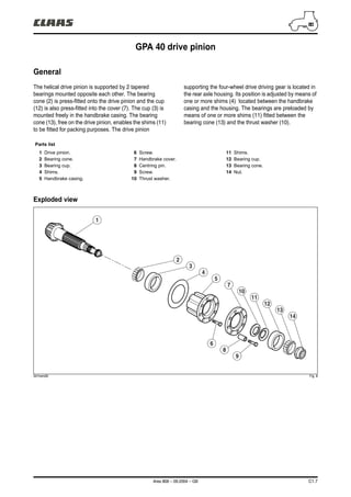
GPA 40 drive pinion
General
The helical drive pinion is supported by 2 tapered
bearings mounted opposite each other. The bearing
cone (2) is press-fitted onto the drive pinion and the cup
(12) is also press-fitted into the cover (7). The cup (3) is
mounted freely in the handbrake casing. The bearing
cone (13), free on the drive pinion, enables the shims (11)
to be fitted for packing purposes. The drive pinion
supporting the four-wheel drive driving gear is located in
the rear axle housing. Its position is adjusted by means of
one or more shims (4) located between the handbrake
casing and the housing. The bearings are preloaded by
means of one or more shims (11) fitted between the
bearing cone (13) and the thrust washer (10).
Exploded view
341hsm26 Fig. 8
Parts list
1 Drive pinion.
2 Bearing cone.
3 Bearing cup.
4 Shims.
5 Handbrake casing.
6 Screw.
7 Handbrake cover.
8 Centring pin.
9 Screw.
10 Thrust washer.
11 Shims.
12 Bearing cup.
13 Bearing cone.
14 Nut.
1
2
3
4
5
7
6
8
9
10
11
12
13
14
2. C1.8 Ares 806 – 09.2004 – GB
GPA 40 drive pinion
Removal/refitting
Uncouple the tractor between the gearbox and rear axle
as follows:
– Refer to Chapter "H" for partial cab removal.
Operations 1 to 7.
– Drain the transmission system.
– Remove the reservoir(s) and disconnect the pipes,
hoses and wiring harnesses interfering with the
uncoupling operation.
– Make the tractor safe with stands and trolleys.
– Chock the tilt between the front axle and the cradle.
– Release the transmission lock.
– Remove the RH and LH hydraulic covers.
– Remove the PTO clutch (15) (see paragraph
concerned).
– Remove the four-wheel drive shaft and clutch (16) (see
chapter "D").
– Remove the crawler speed system if fitted (see
chapter "B").
– Remove the retaining ring (17), washer and shims.
– Remove the driving gear (18) from the 4WD casing.
– Remove the pivot screw (19) from the handbrake
compensator.
– Free and secure the nut (14) with spanner
n° 60 05 006 310. Fit special socket n° 60 05 006 311
at the end of the drive pinion (Fig. 10) and turn
clockwise.
– Only release the nut.
– Remove the eight screws (9) and two screws (6).
341hsm27 Fig. 9
341hsm28 Fig. 10
15
17
16
18
19
14
6
60 05 006 311
9
60 05 006 310
3. Ares 806 – 09.2004 – GB C1.9
GPA 40 drive pinion
– Extract the handbrake casing using an extension and
socket n° 60 05 006 311.
– Recover the protrusion distance adjustment shims (4).
– Position the casing vertically on the drive pinion.
– Finish unscrewing the nut (14) and discard it.
– Remove the bearing cone (13), shims (11) and thrust
washer (10).
– Remove the cover (7) and handbrake device (see
paragraph concerned).
– Separate the drive pinion from the handbrake casing.
– Extract the cone (2) and cup (3) if necessary.
N.B.: If the drive pinion, tapered bearings, casing,
cover, thrust washer or rear axle housing need to be
replaced, it is essential to adjust the drive pinion
protrusion distance and then shim the tapered
bearings.
– Clean and inspect all parts, replace all faulty parts. If
removed, fit the bearing cone (2) fully onto the drive
pinion using an appropriate jig and a press and bring
the cup (3) into contact inside the casing (5).
– Refit the assembly in reverse order to removal.
– The shims (11) must be fitted between the thrust
washer (10) and the bearing cone.
– Lubricate the bearing cones.
– Screw on the new nut (14); it will be tightened up once
the casing has been refitted inside the rear axle
housing.
– Fit the measured shims (4) between the casing and the
housing.
341hsm29 Fig. 11
341hsm30 Fig. 12
60 05 006 311
14
13
11
7
5
4
10
3
2
4. C1.10 Ares 806 – 09.2004 – GB
GPA 40 drive pinion
– Refit the casing in the housing in reverse order to
removal.
– Fit the handbrake compensator (20) at the same time.
– Coat the screws with Frenetanch (242).
– Tighten the screws progressively to fit the casing
correctly.
– Finish tightening to 12 ± 1 daN.m. .
– Adjust the braking device (see paragraph concerned).
– Remove and coat the nut (14) lightly with
Frenbloc (270), and hold it with spanner
n° 60 05 006 310.
– Turn the drive pinion anticlockwise with tool
n° 60 05 006 311 to tighten to 23 ± 2 daN.m.
– Lock the nut in the 3 grooves.
– Fit the driving gear (18) of the 4 drive wheels.
– Position the shims between the thrust washer and the
gear to obtain 0,05 ± 0,05 mm play.
– Refit the equipment in reverse order to removal and
couple up the tractor.
341hsm31 Fig. 13
341hsm32 Fig. 14
341hsm33 Fig. 15
20
60 05 006 311
60 05 006 310
6
005
0063
11
14
0,05
± 0,05
mm
18
5. Ares 806 – 09.2004 – GB C1.11
GPA 40 drive pinion
Setting and adjusting the protrusion
distance of the drive pinion
N.B.: Shim thicknesses "E1" and "E2" must be
produced with no more than 3 shims. The drive pinion
and the ring gear are paired by a number and a letter
engraved on each component.
Setting the drive pinion bearings
The brake casing must be free of the braking device.
– Assemble the cover with two screws (9). Setting will be
carried out on the press.
– Fit the prelubricated tapered bearings with an
appropriate jig.
– Make a set-up with the thrust washer and a greater
thickness of shims.
– Tighten a new nut (14) provisionally to 23 ± 2 daN.m.
Measuring "X"
On a press equipped with a pressure gauge.
– Position the casing vertically with the pinion bearing on
the base (Fig. 17).
– Exert 200 daN axial pressure on the cover with an
appropriate jig.
– Rotate the casing a few times to seat the bearings.
– Measure the value "X".
Measuring "Y"
On a press equipped with a pressure gauge.
– Position the casing vertically on the base (Fig. 18).
– Exert 200 daN axial pressure at the end of the drive
pinion shaft.
– Rotate the casing a few times to seat the bearings.
– Measure the value "Y".
341hsm34 Fig. 16
341hsm35 Fig. 17
341hsm36 Fig. 18
14
9
X
X
Y
Y
6. C1.12 Ares 806 – 09.2004 – GB
GPA 40 drive pinion
Calculating J1
"J1" corresponds to the measured play.
J1 = X – Y
Thickness "E1" of shims (11)
Determine thickness "E1" corresponding to the higher
number of shims minus "J1" minus a preload "P1"
of 0,11 ± 0,03 mm.
E1 = J1 + P1
The maximum number of shims will be 3.
For example, if X = 9,60, Y = 8,20 and the higher shim
thickness is 4
J1 = 9,60 – 8,20 = 1,40 mm
"E1" (minimum) = 4 – 1,40 – 0,14 = 2,46
"E1" (maximum) = 4 – 1,40 – 0,08 = 2,52
According to the example, shims with a thickness of
between 2,46 and 2,52 mm should be inserted.
– Remove the nut (14) and bearing cone (13) and insert
the measured thickness of shims "E1".
– Refit the cone and tighten the nut to 23 ± 2 daN.m.
N.B.: The drag torque must now be checked.
– Place the casing in a vice. Use a torque wrench and
socket n° 60 05 006 311.
– Complete a few regular turns to measure the drag
torque. This value should be between 0,15
and 0,4 daN.m.
– Adjust the setting by removing or adding shims in an
effort to get as close as possible to the 0,4 daN.m
tolerance.
341hsm37 Fig. 19
341hsm38 Fig. 20
11
14 13
660 05 006 311
7. Ares 806 – 09.2004 – GB C1.13
GPA 40 drive pinion
Setting the drive pinion protrusion distance
Measuring "A"
Measure "A" with a depth gauge (Fig. 21). Distance
between the end of the drive pinion and the bearing
surface of the casing.
Thickness "E2" of shims (4)
Determine "E2" according to "A" and – 100,23 mm.
Given that – 100,23 mm corresponds to the result of the
nominal housing and differential torque dimensions.
E2 = – 100,23 + A
For example, if A = 100,85
E2 = – 100,23 + 100,85 = 0,62
According to the example, shims with a thickness
of 0,60 mm must be inserted.
– Proceed with refitting the braking device.
– Refit the handbrake casing and drive pinion assembly
according to the procedure described on the previous
pages.
341hsm39 Fig. 21
A
8. C1.14 Ares 806 – 09.2004 – GB
5" differential
General
The ring gear is riveted to the differential case. The
differential assembly rotates on 2 tapered bearings held
by 2 side supports (2) and (36) screwed onto the housing.
The differential assembly consists of 2 half-cases
containing 4 planet gears and 2 sun gears. The differential
assembly is preloaded by means of shims (32) placed
between the cone (31) and the left-hand bearing (36).
The backlash between the drive pinion and the ring gear
is obtained by means of shims (7) inserted between the
cup (6) and the differential half-case (10).
Differential lock
The multidisc locking device located on the left-hand side
of the half-case (19) comprises.
– A unit (21) containing the discs (23) and the
backplates (24).
– A hub (25) connected by splines to the sun gear of the
LH axle tube.
– An assembled cover (29) for the piston (27) supported
by a tapered bearing.
The piston chamber housed in the cover (19)
communicates with a duct in the bearing (36), enabling
low pressure (17 bar) to act on the piston. The duct is
sealed by 2 piston rings (34).
Clutched position
When the differential locking solenoid valve is activated,
oil flows into the piston chamber. The piston compresses
the intermediate plates (24) and the discs (23) connected
to the hub (25) and case (21) respectively. In this clutched
position, the input sun gear of the RH and LH axle tubes
rotate at the same speed.
Declutched position
When power is turned off, the piston withdraws and the
discs and intermediate plates are decompressed,
enabling the sun gears and planets gears to fulfil their
differential function.
Parts list
1 Screw.
2 RH bearing.
3 O-ring.
4 Centring pin.
5 Bearing cone.
6 Bearing cup.
7 Shims.
8 Deflector.
9 Rivets.
10 Differential half-case.
11 Friction ring.
12 Ring gear.
13 Drive pinion.
14 Sun gear.
15 Friction washer.
16 Planet gear.
17 Spider shaft.
18 Friction ring.
19 Differential half-case.
20 Screw.
21 Differential locking case.
22 Screw.
23 Differential locking disc.
24 Differential locking backplate.
25 Differential locking hub.
26 O-ring.
27 Piston.
28 O-ring.
29 Differential locking cover.
30 Bearing cup.
31 Bearing cone.
32 Shims.
33 O-ring.
34 Sealing piston ring.
35 Centring pin.
36 LH bearing.
37 Screw.
38 O-ring.
39 Supply tube.
40 Seal.
41 Coupling.
10. C1.16 Ares 806 – 09.2004 – GB
5" differential
342hsm29 Fig. 23
Removing/refitting the bearings
LH bearing
N.B.: The bearing (36) and sealing rings (34) of the
differential lock can be worked on by removing just
the left-hand axle tube.
– Remove the left-hand axle tube (see paragraph
concerned).
– Unscrew the coupling (41) and remove the transfer
tube (39).
– Remove the brake piston (see chapter "C3").
– Remove the forward motion sensor (42) from the
housing.
– Remove the screws (37) from the bearing (36), fit 2
diametrically opposed locating studs "A" into the
housing and tighten them firmly up against the
differential locking cover (29) (Fig. 26).
– Extract the bearing with the aid of the tapped holes and
two screws (B) and recover the cone (31) and
shims (32) (Fig. 26).
N.B.: The locating studs (A) hold and centre the
differential assembly in the housing. Do not loosen
the studs or the assembly may become skewed and
section the sealing rings (34) on refitting the bearing.
342hsm30 Fig. 24
342hsm31 Fig. 25
342hsm32 Fig. 26
41
42
39
29
37
36
32
31
34
29
36 A
B
B
11. Ares 806 – 09.2004 – GB C1.17
5" differential
342hsm33 Fig. 27
N.B.: If the bearing block or roller bearing has to be
replaced, always adjust the differential roller bearings
(see following pages).
– Check that the centring pin (35), shims (32) and
bearing cone (31) are present.
– Check that the sealing rings (34) are not damaged and
rotate normally in their groove. After checking, remove
the rings and coat them with miscible grease so that
they remain seated in the groove while the support is
refitted.
– Fit new O-rings (33) and (38).
– Slide the bearing (36) onto the locating studs (A) and
tighten 4 screws (37) evenly and alternately
to 11,5 ± 1,5 daN.m (Fig. 28 and 29).
– Remove the locating studs. Fit and tighten the other
screws to the same torque.
– Position the supply tube and coupling.
– Refit the brake piston (see chapter "C3").
– Check that the seal (33) is correctly positioned.
– Refit the left-hand axle tube (see paragraph
concerned).
RH bearing
The removal/refitting procedure for the right-hand bearing
is similar to the one for the left-hand bearing. Except that
the RH bearing is not equipped with hydraulic ducts and
seals (34).
342hsm34 Fig. 28
342hsm35 Fig. 29
35 3133
34 32
37
38
35
A
36
37
A
12. C1.18 Ares 806 – 09.2004 – GB
5" differential
Removing/refitting the differential
case
– Drain the transmission system.
– Disconnect the PTO control cables and pipes.
– Remove the linkage and lift accessories obstructing the
uncoupling of the PTO housing.
– Remove the PTO speed sensor from the rear axle to
avoid damaging it.
– Remove the PTO housing with a chain and hoist.
– Remove the countershaft connected to the clutch.
– Remove the axle tubes (see paragraph concerned).
– Position rear differential stand n° 60 05 006 319 in
support. (This stand requires base n° 60 05 006 314).
With the aid of the stand, keep the differential assembly
in line with the RH and LH bearings ((2) and (36)
respectively).
– Remove the RH and LH bearings according to the
procedure described above.
– Recover the cones (31) and (5) and shims (32) from
the LH bearing.
– Remove the differential case from the rear axle
housing (Fig. 31).
N.B.: As space is restricted around the differential
case, it is essential to fit the hydraulic tubes in the
rear axle housing before refitting the case.
In order to avoid damaging the sealing rings (34), it is
necessary to align the differential assembly correctly with
the housing axis before fitting the bearings (2) and (36).
With the aid of the tool, insert the differential assembly into
the central housing and hold it in line with the axle tubes.
– Fit the measured thickness of shims (7) behind the
cup (6).
– Fit the bearing (2) according to the procedure
described above. 342hsm36 Fig. 30
342hsm0r Fig. 31
5
2
7
6
32
31
36
60 05 006 319
13. Ares 806 – 09.2004 – GB C1.19
5" differential
Prepare to fit the bearing (36) as follows:
– Slide the bearing cone onto setting tool
n° 60 05 006 309 adapted to the differential case.
Using the tool, centre the differential assembly in the
housing while turning the central screw clockwise as
far as it will go.
– Fit 2 diametrically opposed locating studs (A) into the
housing and tighten them firmly. This method keeps
the differential assembly centred after removing tool
n° 60 05 006 309.
– Remove the tool and recover the bearing cone.
– Check the presence of the centring pin (35) and shims.
– Fit a new O-ring (33).
– Check that the sealing rings (34) are not damaged and
rotate normally in their groove.
– Fit the bearing (36) according to the procedure
described above. After fitting the bearings, check the
rotation of the differential assembly by hand.
– Refit the brake pistons (see chapter "C3").
– Refit the axle tubes (see paragraph concerned). If
removed, refit the PTO housing.
– Couple up the tractor between the intermediate
housing and the rear axle housing.
– Check the operation of all controls (mechanical,
hydraulic and electronic). Road test.
– Check the mating surfaces and hydraulic couplings for
leaks.
342hsm38 Fig. 32
342hsm39 Fig. 33
60 05 006 309
3635
33
34
14. C1.20 Ares 806 – 09.2004 – GB
5" differential
Removing/refitting the differential
lock
– Remove the differential case as described in the
procedure above.
– Position the differential case with the cover (29) facing
up.
– Remove the screws (20).
– Remove the cover (29), discs (23), backplates (24) and
hub (25).
– Remove the screws (22) and case (21).
– Tap the cover (29) lightly on a wooden block to remove
the piston (27).
– Replace the O-rings. Drive out the cup (30) if
necessary.
N.B.: If the case (21), cover (29) and bearing (36) need
to be replaced, the differential case must be shimmed
and the backlash between the drive pinion and the
ring gear checked (see following pages).
– Check that the hydraulic duct in the cover is not
blocked.
– Lubricate the new seals before fitting.
– Refit the piston (27) by tapping gradually and
alternately around the edge with a mallet.
– Check that there are no seal fragments after fitting.
– Coat the screws (22) lightly with Frenbloc (270) and
tighten to 11,5 ± 1,5 daN.m. .
– Fit the hub, backplates and discs.
– Position the assembled cover (29) of the piston (27).
– Fit and tighten the screws (20) coated with
Frenbloc (270) to 11 ± 1 daN.m.
– Check manually that the discs and backplates are not
stressed.
– Refit the differential case as described in the procedure
above.
342hsm40 Fig. 34
27
20
30
29
25
23
24
21
22
15. Ares 806 – 09.2004 – GB C1.21
5" differential
Removing/refitting the planet gears,
sun gears and ring gear
– Remove the differential locking system.
– Separate the half-cases (10) and (19).
N.B.: These parts have the same number. They must
imperatively be coupled.
– Remove the sun gears (14) fitted with friction rings (11)
and (18), planet gears (16), washers and spider (17).
If necessary, drive out the bearing cup on half-
casing (10) and recover the shims.
– Extract and discard the deflector. The drive pinion must
be replaced if the ring gear is replaced.
N.B.: These parts have the same number. They must
imperatively be coupled.
The ring gear and case are originally riveted together. For
repair, the rivets are replaced by screws and nuts
referenced in the spare parts catalogue.
– Punch (on the ring gear teeth side) the centre of each
rivet (9). Using a 5 mm dia. bit, drill the rivets to a depth
of 12 mm (Fig. 36).
– Drill again to an identical depth with a 12 mm bit.
– Drive the rivets hard with a suitable drift punch
(Fig. 37).
– Clean the bearing surfaces of the new ring gear (12)
and half-case (10), as well as the screws and nuts.
– Coat the initial threads of the screws with
Frenbloc (270) and position them in the ring gear and
case.
– Tighten the nuts to 18 ± 2 daN.m.
– Refit the deflector, shims and cup.
– Refit the planet gears and sun gears in reverse order to
removal.
– Tighten the screws (22) coated with Frenbloc (270)
to 11,5 ± 1,5 daN.m.
342hsm41 Fig. 35
342hsm42 Fig. 36
342hsm43 Fig. 37
22
19 16
18 11
10
9
12
14
17
10
12
16. C1.22 Ares 806 – 09.2004 – GB
5" differential
Adjusting the backlash
N.B.: The backlash to be obtained between the ring
gear and drive pinion ensures that the final drive is
reliable and that the assembly operates correctly.
This backlash must be checked following:
– Adjustment of the protrusion distance.
– Shimming of the differential case.
With the aid of a suitable extractor, remove the cup (6)
and discard the deflector (8).
– Position shims (7) with a thickness of 0,20 mm on the
differential half-case (10).
– Fit the cup (6) up against the shims without the
deflector (8).
– Refit the differential case (see corresponding
paragraph) with only the RH bearing (2). On the LH
side, fit tool n° 60 05 006 309 with the roller
bearing (31). .
– Tighten the tool's centre screw to 1 daN.m (Fig. 39).
– Turn the differential to seat the bearings.
– Check once again that the tool screw is tight.
– Couple and fasten the intermediate housing
temporarily with the rear axle housing by tightening the
screws to 61 ± 7 daN.m. With the PTO housing
removed, place the plunger of a dial gauge at half-
length on a tooth of the ring gear (Fig. 40).
– Check that the backlash is 0,35 ± 0,10 mm.
– Carry out this operation at 3 points of the ring gear. If
the presetting is incorrect, the principle consists of
removing or adding shims (7) until the backlash is
within the aforementioned tolerance.
– Insert the selected shims (7).
– Partly insert a new deflector (8). The deflector will be
fitted completely with the cup (6).
– Check that the cup is bearing properly on the shims
and is in contact with the deflector.
– The next essential step is to shim the differential case
roller bearings.
342hsm44 Fig. 38
342hsm45 Fig. 39
342hsm46 Fig. 40
6
7
8
2
10
31
17. Ares 806 – 09.2004 – GB C1.23
5" differential
Shimming the differential case roller
bearings
N.B.: If the rear axle housing, ring gear, tapered roller
bearings and bearing blocks need to be replaced, the
differential case must be shimmed. Check
beforehand that the backlash is correct.
– Fit the differential (see paragraph concerned).
– Fit the RH bearing with the measured number of shims.
On the LH side, fit tool n° 60 05 006 309 with the roller
bearing (31). Using two bolts, mount the tool on the
housing (Fig. 41).
– Tighten the centre bolt to 1 daN.m.
N.B.: Turn the ring gear a few times to seat the cones
correctly in the cups. Check the centre bolt torque
again.
Measuring "Y"
– Determine "Y" according to "A" and "B".
– Measure "A", the distance between the top of the
bearing and the contact surface of the shims, with tool
n° 60 05 006 309 (Fig. 42 and 43).
– Measure "B", the distance between the top of the
bearing and the contact surface of the bearing on the
housing, with tool n° 60 05 006 309 (Fig. 42).
Y = B – A
342hsm47 Fig. 41
342hsm48 Fig. 42
342hsm49 Fig. 43
31
Y
B
A
60
05
006
309
A
18. Thank you very much for
your reading. Please Click
Here. Then Get COMPLETE
MANUAL. NO WAITING
NOTE:
If there is no response to
click on the link above,
please download the PDF
document first and then
click on it.
19. C1.24 Ares 806 – 09.2004 – GB
5" differential
Measuring "X"
Using a suitable depth gauge, measure "C" and determine
dimension "X" between the bearing cone (31) and the
contact surface of the bearing on the housing (Fig. 45):
X = C – 10
(10 mm is the thickness of measuring tool
n° 60 05 006 309).
Thickness "E" of shims (32)
Determine "E" according to "X" and "Y" plus a preload
P1 = 0,10 ± 0,05 mm.
E = X – Y + P1
For example, if A = 39,65, B = 103,45 and C = 74,5
Y = 103,45 – 39,65 = 63,8
X = 74,5 – 10 = 64,5
E (minimum) = 64,5 – 63,8 + 0,05 = 0,75
E (maximum) = 64,5 – 63,8 + 0,15 = 0,85
According to the example, the shim thickness must be
between 0,75 and 0,85 mm.
– Remove the tool and the bearing cone (31). Place
shims (32) to a thickness "E" on the bearing (36).
– Fit the RH bearing (36) (see paragraph concerned).
– Refit the assembly as described in the procedures on
the pages concerned.
342hsm50 Fig. 44
342hsm51 Fig. 45
342hsm52 Fig. 46
C
31
X
C
32
31
36