1. Atles 906 – 09.2004 – GB C1.7
GPA 30 drive pinion
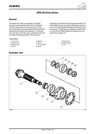
General
The helical drive pinion is supported by 2 tapered
bearings mounted opposite each other. The bearing
cone (2) is press-fitted onto the drive pinion and the
cups (3) and (9) are also press-fitted into the intermediate
housing and the bearing (5) respectively. The bearing
cone (10), free on the drive pinion, enables the shims (8)
to be fitted for packing purposes. The drive pinion
supporting the 4-wheel drive driving gear is located in the
intermediate housing. Its position is adjusted by means of
one or more shims (6) placed between the bearing (5) and
the housing. The bearings are preloaded by means of one
or more shims (8) fitted between the bearing cone (10)
and the thrust washer (7).
Exploded view
342hsm16 Fig. 8
Nomenclature
1 Drive pinion.
2 Bearing cone.
3 Bearing cup.
4 Screw.
5 Bearing.
6 Shims.
7 Thrust washer.
8 Shims.
9 Bearing cup.
10 Bearing cone.
11 Nut.
7
6
5
4
3
2
1
8
9
10
11
2. C1.8 Atles 906 – 09.2004 – GB
GPA 30 drive pinion
Removal/refitting
Uncouple the tractor between the gearbox and the
intermediate housing (12) as follows:
– Refer to Chapter "H" for partial cab removal.
Operations 1 to 7.
– Drain the transmission system.
– Remove the reservoir(s) and disconnect the pipes,
hoses and wiring harnesses interfering with the
uncoupling operation.
– Make the tractor safe with stands and trolleys.
– Chock the tilt between the front axle and the cradle.
– Release the ratchet of the "Park Lock" transmission
lock.
– Mark the position and extract the sleeve between the
drive pinion and the lower shaft.
– Remove the bearing/hydraulic pump driving gear
assembly.
– Disconnect the handbrake mechanism control shaft.
– Free and secure the nut (11) with spanner
n° 60 05 006 310.
– Fit special socket n° 60 05 006 311 to the end of the
drive pinion and turn in a clockwise direction (Fig. 10).
– Remove the bearing cone (10), shims (8) and thrust
washer (7).
342hsm17 Fig. 9
342hsm18 Fig. 10
342hsm19 Fig. 11
12
60 05 006 310
60 05 006 311
11
10
11
8
7
3. Atles 906 – 09.2004 – GB C1.9
GPA 30 drive pinion
342hsm20 Fig. 12
– Uncouple the intermediate housing (12) from the rear
axle.
– Remove 2 diametrically opposite screws (13) from the
bearing (5).
– Screw 2 locating studs in replacement (Fig. 13).
– Finish removing the other screws.
– Extract the bearing (5) with the aid of 2 screws inserted
into the tapped holes.
– Remove the shims (6).
– Remove the handbrake casing and the 4-wheel drive
gear (17).
– Make a visual note of the position of the parts.
– Remove the retaining ring (14).
– Remove the screws (15).
– Separate the handbrake casing from the bearing (5).
– Remove the discs, the intermediate plates and the
handbrake mechanism.
If necessary, extract the bearing cups and the cone from
the drive pinion.
342hsm21 Fig. 13
342hsm22 Fig. 14
5
13
13
6
5
1551417
4. C1.10 Atles 906 – 09.2004 – GB
GPA 30 drive pinion
342hsm23 Fig. 15
N.B.: If the drive pinion, tapered roller bearings,
bearing block, thrust washer or intermediate housing
need to be replaced, it is essential to adjust the drive
pinion protrusion distance and then shim the tapered
bearings.
– Clean and inspect all parts, replace all faulty parts. If
removed, fit the bearing cone (2) fully onto the drive
pinion using an appropriate jig and a press and bring
the cup (3) into contact with the bearing block (5).
– Lubricate the roller bearing with transmission oil.
– Refit the handbrake mechanism, the intermediate
plates and the discs.
– Assemble the handbrake casing and the bearing.
– Slide the drive pinion, handbrake and bearing (5)
assembly with the aid of locating studs and with the
measured number of shims (6).
– Drive the screws (13) gradually and alternately to fit the
bearing correctly.
– Coat the screws (13) lightly with Frenbloc (270) and
tighten to 12 ± 1 daN.m.
– The thrust washer (7) must be placed in contact with
the shoulder in the drive pinion.
– Slide on the shims (8).
– Lubricate the bearing cone (10) with transmission oil
and mount it on the drive pinion in contact with the
shims.
– Degrease the nut (11) and the drive pinion threads.
– Coat the nut thread lightly with Frenbloc (270) and
immobilise it with spanner n° 60 05 006 310. Using
socket n° 60 05 006 311, turn the drive pinion
anticlockwise to a torque of 23 ± 2 daN.m.
Important: Check drive pinion rotation manually.
Lock the nut by deforming its flange, without breaking
it, using a suitable tool.
– Fit and adjust the brake control.
– Refit the bearing/hydraulic pump driving gear
assembly.
– Refit the ratchet and sleeve of the "Park Lock"
transmission lock.
– Couple up the tractor.
N.B.: If the ring gear and drive pinion have needed to
be replaced, check the backlash (see paragraph
concerned).
– Check the operation of all controls. Road test.
– Check the gasket faces for leaks.
– Check the hydraulic couplings for leaks.
10
7
13
5
3
2
6
11
8
5. Atles 906 – 09.2004 – GB C1.11
GPA 30 drive pinion
Drive pinion protrusion distance and shimming
Reminder: It is essential to adjust the pinion
protrusion before shimming the tapered roller
bearings. Do not alter the adjustment without
reviewing the shimming of the drive pinion bearings.
Setting the drive pinion
protrusion distance
Without the handbrake casing and the 4-wheel drive gear.
– Fit the bearing (5) with its bearing cup (3) and without
shims, tighten screws (13) to 12 ± 1 daN.m.
– Slide the drive gear (1) with the bearing cone (2).
– Fit the bearings (9) and (10) and the thrust washer
without shims.
N.B.: The thrust washer (7) will be fitted while the
distance between the bearing ocone and the nut is
being measured.
– Tighten the nut (11) to 4 ± 1 daN.m with tools
n° 60 05 006 310 and n° 60 05 006 311.
– Turn the drive pinion 8 times to seat the bearings
properly.
– Check the nut torque once again.
342hsm24 Fig. 16
7 9 15
3
1321011
6. C1.12 Atles 906 – 09.2004 – GB
GPA 30 drive pinion
342hsm25 Fig. 17
Measuring "X"
Measure "X" with a depth gauge (Fig. 18).
Thickness "E1" of shims (6)
Determine "E1" according to "X", "Y" and "Z".
Given that:
– "Z" corresponds to the nominal dimension determined
between the rear face of the intermediate housing and
the differential axis = 241 ± 0,05 mm.
N.B.: This dimension is marked inside the housing
along the horizontal axis of the differential case.
– "Y" corresponds to the nominal positioning dimension
of the drive pinion in relation to the differential
axis = 139 ± 0,05 mm.
E1 = Z – (X + Y)
For example, if X = 101,35 and Z = 241
"E1" (minimum) = 241 – (101,35 + 138,95) = 0,7
"E1" (maximum) = 241 – (101,35 + 139,05) = 0,6
According to the example, shims with a thickness of
between 0,6 and 0,7 mm should be inserted.
N.B.: Thickness "E1" should be achieved with no
more than 3 shims. The drive pinion and the ring gear
are paired by a number and a letter engraved on each
component.
342hsm26 Fig. 18
Z
X
Y
6
X
51
7. Atles 906 – 09.2004 – GB C1.13
GPA 30 drive pinion
342hsm27 Fig. 19
Setting the drive pinion bearings
N.B.: Always proceed with shimming the roller
bearings after adjusting the drive pinion protrusion
distance.
Without the handbrake casing and the 4-wheel drive gear.
– Mount the bearing (5) with its bearing cup (3) and
shims (6) (thickness "E1") and tighten the screws (13)
to 12 ± 1 daN.m.
N.B.: The thrust washer (7) must be placed in contact
with the shoulder in the drive pinion (Fig. 19).
– Determine a higher thickness of shims (8) to obtain
play.
– Lubricate the bearing cup (9).
– Mount the taper (10). Using spanner n° 60 05 006 310
and socket n° 60 05 006 311, tighten the nut (11)
to 23 ± 2 daN.m.
Measuring "W"
– Position a dial gauge probe on the end of the drive
pinion (Fig. 19).
– Apply an axial tensile force of 45 ± 5 daN and turn the
drive pinion at least 8 times to seats the bearings
correctly.
– Set the dial gauge to zero.
– Apply an axial thrust force of 45 ± 5 daN and turn the
drive pinion at least 8 times to seats the bearings
correctly.
– Measure the value "W".
Thickness "E2" of shims (8)
– Determine thickness "E2" corresponding to the higher
number of shims minus the measured play minus a
preload of 0,07 ± 0,03 mm.
811 7 6 5
910 3 13
0,07 ± 0,03 mm
W
8. C1.14 Atles 906 – 09.2004 – GB
GPA 30 drive pinion
342hsm27 Fig. 20
For example, if the measured play is 0,15 mm and the
higher number of shims is 1 mm
1 – 0,15 = 0,85 mm of shims with zero play and preload.
"E2" (minimum) = 0,85 – 0,1 = 0,75
"E2" (maximum) = 0,85 – 0,04 = 0,81
According to the example, the shim thickness should be
between 0,75 and 0,81 mm.
– Loosen and remove the nut (11). Slide on shims (8) to
the measured thickness "E2" between the thrust
washer (7) and the bearing cone (10).
– Lubricate the two tapered bearings. Using spanner
n° 60 05 006 310 and socket n° 60 05 006 311,
tighten the nut (11) to 23 ± 2 daN.m.
– Turn the drive pinion at least 8 times to seat the
bearings correctly.
– Check that the drive pinion drag torque
is 0,23 ± 0,12 daN.m.
– Loosen and remove the nut (11).
– Refit the handbrake casing and the 4-wheel drive gear
according to the drive pinion refitting procedure.
811 7 6 5
910 3 13
0,07 ± 0,03 mm
W
10. C1.16 Atles 906 – 09.2004 – GB
7" differential
General
The ring gear is screwed onto the differential case. The
differential assembly rotates on 2 tapered bearings held
by 2 side supports and screwed onto the housing. The
differential assembly consists of a case containing 4
planet gears and 2 sun gears. The differential assembly is
preloaded by means of shims (31) placed between the
cone (30) and the left-hand bearing (35). The backlash
between the drive pinion and the ring gear is obtained by
means of shims (7) inserted between the cup (6) and the
differential case (9).
Differential lock
The multidisc locking device located on the left-hand side
of the case (9) comprises.
– A casing (27) containing the discs (22) and the
backplates (23).
– A hub (20) connected to the sun gear of the LH axle
tube.
– A piston (25) fitted in the casing (27).
The piston chamber housed in the casing (27)
communicates with a duct in the bearing (35), enabling
low pressure (17 bar) to act on the piston. The duct is
sealed by two rings (33).
Clutched position
When the differential locking solenoid valve is activated,
oil flows into the piston chamber. The piston compresses
the intermediate plates (23) and the discs (22) connected
to the hub (20) and case (27) respectively. In this clutched
position, the input sun gear of the RH and LH axle tubes
rotate at the same speed.
Declutched position
When power is turned off, the piston withdraws and the
discs and intermediate plates are decompressed,
enabling the sun gears and planets gears to fulfil their
differential function.
Nomenclature
1 Screw.
2 RH bearing.
3 O-ring.
4 Centring pin.
5 Bearing cone.
6 Bearing cup.
7 Shims.
8 Screw.
9 Differential housing.
10 Friction ring.
11 Ring gear.
12 Drive pinion.
13 Sun gear.
14 Friction washer.
15 Planet gear.
16 Locking needle.
17 Screw.
18 Planet gear pin.
19 Differential joint.
20 Sun gear/hub.
21 Friction ring.
22 Differential locking disc.
23 Differential locking backplate.
24 O-ring.
25 Piston.
26 O-ring.
27 Differential locking case.
28 Screw.
29 Bearing cup.
30 Bearing cone.
31 Shims.
32 O-ring.
33 Sealing piston ring.
34 Centring pin.
35 LH bearing.
36 Screw.
37 O-ring.
38 Supply tube.
39 Seal.
40 Coupling.
12. C1.18 Atles 906 – 09.2004 – GB
7" differential
342hsm85 Fig. 22
Removing/refitting the bearings
LH bearing
N.B.: The bearing (35) and sealing rings (33) of the
differential lock can be worked on by removing just
the left-hand axle tube.
– Remove the left-hand axle tube
(see paragraph concerned).
– Unscrew the coupling (40) and remove the transfer
tube (38).
– Remove the brake piston (see chapter "C3").
– Remove the forward motion sensor (41) from the
housing.
– Remove the screws (36) from the bearing (35), fit 2
diametrically opposed locating studs "A" into the
housing and tighten them firmly up against the
differential locking case (27) (Fig. 25).
– Extract the bearing with the aid of the tapped holes
and 2 screws (B) and recover the cone (30) and
shims (31) (Fig. 25).
N.B.: The locating studs (A) hold and centre the
differential assembly in the housing. Do not loosen
the studs or the assembly may become skewed and
section the sealing rings (33) on refitting the bearing.
342hsm86 Fig. 23
342hsm87 Fig. 24
342hsm88 Fig. 25
40
41
38
36
31
35
30
33 27
27
35 A
B
B
13. Atles 906 – 09.2004 – GB C1.19
7" differential
N.B.: If the bearing block or roller bearing has to be
replaced, always adjust the differential roller bearings
(see following pages).
– Check that the centring pin (34), shims (31) and
bearing cone (30) are present.
– Check that the sealing rings (33) are not damaged and
rotate normally in their groove. After checking, remove
the rings and coat them with miscible grease so that
they remain seated in the groove while the support is
refitted.
– Fit new O-rings (32) and (37).
– Slide the bearing (35) onto the locating studs (A) and
tighten 4 screws (36) evenly and alternately
to 11,5 ± 1,5 daN.m. Remove the locating studs.
Fit and tighten the other screws to the same
torque (Fig. 28).
– Position the supply tube and coupling.
– Refit the brake piston (see chapter "C3").
– Check that the seal (32) is correctly positioned.
– Refit the left-hand axle tube (see paragraph
concerned).
RH bearing
The removal/refitting procedure for the right-hand bearing
is similar to the one for the left-hand bearing. Except that
the RH bearing is not equipped with hydraulic ducts and
seals (33).
342hsm89 Fig. 26
342hsm90 Fig. 27
342hsm91 Fig. 28
32
33
35
36
34
37
31
30
34
A
35
36
A
14. C1.20 Atles 906 – 09.2004 – GB
7" differential
Removing/refitting the differential
case
Uncouple the tractor between the intermediate housing
and the rear axle housing as follows:
– Refer to Chapter "H" for partial cab removal.
Operations 1 to 7.
– Drain the transmission system.
– Remove the reservoir(s) and disconnect the pipes,
hoses and wiring harnesses interfering with the
uncoupling operation.
– Make the tractor safe with stands and trolleys.
– Chock the tilt between the front axle and the cradle.
– Release the ratchet of the "Park Lock" transmission
lock.
If necessary, remove the PTO housing.
– Remove the axle tubes (see paragraph concerned).
– Position rear differential stand n° 60 05 006 314 in
support. With the aid of the stand, keep the differential
assembly in line with the RH and LH bearings ((2)
and (35) respectively).
– Remove the RH and LH bearings according to the
procedure described above.
– Recover the cones (30) and (5) and shims (32) from
the LH bearing.
– Remove the differential case from the rear axle
housing (Fig. 30).
N.B.: As space is restricted around the differential
case, it is essential to fit the hydraulic tubes in the
rear axle housing before refitting the case.
In order to avoid damaging the sealing rings (33), it is
necessary to align the differential assembly correctly with
the housing axis before fitting the bearings (2) and (35).
With the aid of the tool, insert the differential assembly into
the central housing and hold it in line with the axle tubes.
– Fit the measured thickness of shims (7) behind the
cup (6).
– Fit the bearing (2) according to the procedure
described above.
342hsm0c Fig. 29
342hsm37 Fig. 30
2
5673330
3235
15. Atles 906 – 09.2004 – GB C1.21
7" differential
Prepare to fit the bearing (35) as follows:
– Slide the bearing cone onto setting tool
n° 60 05 006 309 adapted to the differential case.
Using the tool, centre the differential assembly in the
housing while turning the central screw clockwise as
far as it will go.
– Fit 2 diametrically opposed locating studs into the
housing and tighten them firmly. This method keeps the
differential assembly centred after removing tool
n° 60 05 006 309.
– Remove the tool and recover the bearing cone.
– Check the presence of the centring pin (34) and shims.
– Fit a new O-ring (32).
– Check that the sealing rings (33) are not damaged and
rotate normally in their groove.
– Fit the bearing (35) according to the procedure
described above. After fitting the bearings, check the
rotation of the differential assembly by hand.
– Refit the brake pistons (see chapter "C3").
– Refit the axle tubes (see paragraph concerned). If
removed, refit the PTO housing.
– Couple up the tractor between the intermediate
housing and the rear axle housing.
– Check the operation of all controls (mechanical,
hydraulic and electronic). Road test.
– Check the mating surfaces and hydraulic couplings for
leaks.
342hsm38 Fig. 31
342hsm92 Fig. 32
60 05 006 309
3534
32
33
16. C1.22 Atles 906 – 09.2004 – GB
7" differential
Removing/refitting the differential
lock
– Remove the differential case as described in the
procedure above.
– Position the differential case with the casing (27)
facing up.
– Remove the screws (28).
– Remove the casing (27), discs (22), backplates (23)
and hub (20).
– Tap the casing (27) lightly on a wooden block to
remove the piston (25).
– Recover the friction ring (21).
– Replace the O-rings. Drive out the cup (29) if
necessary.
N.B.: If the case (9), casing (27) and bearing (35) need
to be replaced, the differential case must be shimmed
and the backlash between the drive pinion and the
ring gear checked (see following pages).
– Check that the hydraulic duct in the casing is not
blocked.
– Lubricate the new seals before fitting.
– Refit the piston (25) by tapping gradually and
alternately around the edge with a mallet.
– Check that there are no seal fragments after fitting.
– Fit the hub, backplates and discs.
– Position the casing (27) with the piston (25)
assembled.
– Fit and tighten the screws (28), coated with
Frenbloc (270), to 12 ± 1 daN.m.
– Check manually that the discs and backplates are not
stressed.
– Refit the differential case as described in the procedure
above.
342hsm93 Fig. 33
2827252129
9222320
17. Atles 906 – 09.2004 – GB C1.23
7" differential
Removing/refitting the planet gears,
sun gears and ring gear
– Remove the differential locking system.
– Remove the ring gear.
– Remove the screws (17) and needles (16).
– Drive out the pins (18) by tapping the opposite pin.
– Recover the friction washers (14).
– Remove the planet gears and sun gear.
– If necessary, recover the bearing cup (6) with the
shims (7).
The drive pinion must be replaced if the ring gear is
replaced.
N.B.: These parts have the same number. They must
imperatively be coupled.
Refit the assembly in reverse order to removal while
observing the following instructions:
– Refit the friction rings (10), coated with Scelbloc (648),
using a suitable jig.
– Check that the lubrication ports are not blocked.
– Fit the needles and tighten the screws (17), coated with
Frenbloc (270), to 3 ± 0,5 daN.m.
– Fit the ring gear.
– Tighten the screws (8), coated with Frenbloc (270),
to 30 ± 2 daN.m.
342hsm94 Fig. 34
16 171814
6 8
17
16
18
107
18. Thank you very much for
your reading. Please Click
Here. Then Get COMPLETE
MANUAL. NO WAITING
NOTE:
If there is no response to
click on the link above,
please download the PDF
document first and then
click on it.
19. C1.24 Atles 906 – 09.2004 – GB
7" differential
Adjusting the backlash
N.B.: The backlash to be obtained between the ring
gear and drive pinion ensures that the final drive is
reliable and that the assembly operates correctly.
This backlash must be checked following:
– Adjustment of the protrusion distance
– Shimming of the differential case.
Remove the cup (6) using a suitable extractor.
– Position shims (7) with a thickness of 0,20 mm on the
differential case (9).
– Fit the cup (6) up against the shims.
– Refit the differential case with only the RH bearing
(see paragraph concerned). On the LH side, fit tool
n° 60 05 006 309 with the roller bearing (30) (Fig. 36).
– Tighten the tool's centre screw to 1 daN.m.
– Turn the differential to seat the bearings.
– Check once again that the tool screw is tight.
– Couple and fasten the intermediate housing
temporarily with the rear axle housing by tightening the
screws to 61 ± 7 daN.m. With the PTO housing
removed, place the plunger of a dial gauge at half-
length on a tooth of the ring gear (Fig. 37).
– Check that the backlash is 0,35 ± 0,10 mm.
– Carry out this operation at 3 points of the ring gear. If
the presetting is incorrect, the principle consists of
removing or adding shims (7) until the backlash is
within the aforementioned tolerance.
– Insert the selected shims (7).
– Check that the cup is bearing properly on the shims.
– The next essential step is to shim the differential case
roller bearings.
342hsm95 Fig. 35
342hsm96 Fig. 36
342hsm46 Fig. 37
7
6
9
30
20. Atles 906 – 09.2004 – GB C1.25
7" differential
Shimming the differential case roller
bearings
N.B.: If the rear axle housing, ring gear, tapered roller
bearings and bearing blocks need to be replaced, the
differential case must be shimmed. Check
beforehand that the backlash is correct.
– Fit the differential (see paragraph concerned).
– Fit the RH bearing with the measured number of shims.
On the LH side, fit tool n° 60 05 006 309 with the roller
bearing (30). Fasten the tool to the housing with 2
screws.
– Tighten the centre bolt to 1 daN.m.
N.B.: Turn the ring gear a few times to seat the cones
correctly in the cups. Check the centre bolt torque
again.
Measuring "Y"
– Determine "Y" according to "A" and "B".
– Measure "A", the distance between the top of the
bearing and the contact surface of the shims, with a
depth gauge.
– Measure "B", the distance between the top of the
bearing and the contact surface of the bearing on the
housing.
Y = B – A
342hsm97 Fig. 38
342hsm98 Fig. 39
30
B
A
Y
21. C1.26 Atles 906 – 09.2004 – GB
7" differential
Measuring "X"
Using a suitable depth gauge, measure "C" and
determine dimension "X" between the bearing cone (30)
and the contact surface of the bearing on the housing
(Fig. 40 and 41):
X = C – 10 mm
(10 mm is the thickness of measuring tool
n° 60 05 006 309).
Thickness "E" of shims (31)
Determine "E" according to "X" and "Y" plus a preload
P1 = 0,10 ± 0,05 mm.
E = X – Y + P1
For example, if A = 39,65, B = 103,45 and C = 74,5
Y = 103,45 – 39,65 = 63,8
X = 74,5 – 10 = 64,5
E (minimum) = 64,5 – 63,8 + 0,05 = 0,75
E (maximum) = 64,5 – 63,8 + 0,15 = 0,85
According to the example, the shim thickness must be
between 0,75 and 0,85 mm.
– Remove the tool and the bearing cone (30). Place
shims (31) to a thickness "E" on the bearing (35).
– Fit the RH bearing (35) (see paragraph concerned).
– Refit the assembly as described in the procedures on
the pages concerned.
342hsm99 Fig. 40
342hsm0a Fig. 41
342hsm0b Fig. 42
30
C
X
C
30
31
35
30