This document provides instructions for diagnosing and addressing issues with a vehicle's suspension system. It includes a table to help determine the most likely causes of common suspension problems based on symptoms. It also provides steps to check wheel alignment, including measuring toe-in, adjusting toe-in if needed, and inspecting camber, caster and steering axis inclination. If those values are outside specifications, the document describes how to adjust camber by selecting the appropriate shock absorber mounting bolts.
2008 toyota prius service repair manualfjjskejdmdn
This document provides information on diagnosing and addressing issues with a vehicle's suspension system. It includes a table to help determine the cause of suspension problems based on symptoms. Potential causes are listed in order of probability. The document also provides specifications and adjustment procedures for inspecting and adjusting the front and rear wheel alignment, toe-in, camber, and vehicle height. Charts are included to help select the correct bolts when adjusting camber.
1) O documento fornece instruções sobre a remoção e instalação do motor da motocicleta Honda CB500, listando os componentes e sequência de remoção.
2) É necessário remover outros componentes como o escapamento, radiador e tampa do pinhão de transmissão antes de remover o motor.
3) O motor deve ser apoiado com um suporte ou macaco e removido em 18 etapas, começando pelos conectores elétricos e terminando com o próprio motor.
Manual de serviço cb400 (1980) ms.001 05-80 manivelaThiago Huari
O documento fornece instruções para remoção e instalação de componentes da árvore de manivelas e balanceador de um motor CB400, incluindo especificações técnicas e limites de serviço. É detalhado o procedimento para inspeção e substituição de bronzinas, balanceador, bielas e demais componentes, com ênfase na seleção correta de bronzinas de acordo com seus códigos de cores.
Toyota 52 6 fgu30 forklift service repair manualhjsemmmd
This manual provides service procedures for the Toyota Forklift 6FGU15-30. It covers models from July 1995 and notes that designs may have changed. It lists repair manuals for mounted engines to use as a reference along with this manual. The manual includes an exterior views section, information on vehicle models and frame numbers, general tips, standard torque specifications, and a periodic maintenance schedule. It is intended to provide technicians with correct servicing procedures for these forklift models.
Manual do propietário cb400 80~82 mp001_03-80Thiago Huari
Este manual fornece instruções sobre o uso e manutenção de uma motocicleta Honda. Ele explica a localização e função dos controles e instrumentos, procedimentos de partida, direção e manutenção básica. O manual também contém especificações técnicas e um plano de manutenção.
Este documento descreve os requisitos e procedimentos para a inspeção de segurança veicular de eixos e suspensão de veículos leves e pesados de acordo com a norma técnica brasileira NBR 14040-8. A norma especifica os itens a serem inspecionados, equipamentos necessários, classificação de defeitos e procedimentos de teste para verificar o funcionamento correto dos sistemas de suspensão.
Manual serviço cb400 ii cb400 policial (1982) suplemento ms443821 p cb400ii...Thiago Huari
Este documento fornece informações sobre a manutenção e reparos das motocicletas Honda CB 400 II e CB 400 Policial, incluindo:
1) Diagramas elétricos e localização de cabos e fiações;
2) Especificações técnicas e procedimentos para roda dianteira e sistema de direção;
3) Detalhes sobre equipamentos especiais da versão Policial.
1) Este documento fornece instruções para diagnosticar falhas no sistema SPLIT usando o código de pisca da luz piloto.
2) O código de pisca indica o problema, como sensor defeituoso ou válvula com curto-circuito.
3) Medições de resistência nos componentes elétricos podem ajudar a identificar problemas no módulo ou circuito.
Full OBD2 Network Trouble Code List (UXXXX)Tim Miller
Check the OBD2 code list (UXXXX) to find out what the codes mean on your car.
>> NEXT STEP: https://www.obdadvisor.com/codes/
Visit our site, and type the code in the search box. You will get more information about the code including causes, symptoms, fixes, and repair costs.
Reading and clearing the codes will become easier with a scan tool.
>> READ MORE: https://www.obdadvisor.com/best-obd2-scanner-review/
This article shows a helpful in-depth review of the 9 best OBD2 scan tools from me, an experienced auto mechanic who has used and tested all of them.
Este documento descreve os requisitos para a inspeção de segurança veicular relacionada à iluminação de veículos leves e pesados de acordo com a norma técnica brasileira NBR 14040-5. Ele especifica os itens a serem inspecionados, como faróis, lanternas e luzes internas, e classifica possíveis defeitos encontrados como leves, graves ou muito graves.
Manual de serviço cb600 f hornet freio hidraulicoThiago Huari
O documento fornece instruções e especificações para o sistema de freio hidráulico de uma motocicleta. As seções incluem localização de componentes, valores de torque, diagnóstico de defeitos, substituição de fluido de freio, pastilhas e discos de freio.
Manual serviço c 100 biz c-100 biz es c-100 biz+ (2002) - 00 x6b-gce-763 tran...Thiago Huari
1) O documento fornece instruções para a separação das carcaças do motor, inspeção e montagem da árvore de manivelas e transmissão.
2) Inclui especificações técnicas, ferramentas necessárias e procedimentos para substituição dos rolamentos.
3) Fornece também informações sobre diagnóstico de defeitos comuns na árvore de manivelas e transmissão.
1) O documento fornece informações técnicas sobre motores diesel Cummins, Citröen e suas peças, incluindo dados sobre pistões, anéis, camisas, filtros e torque de aperto.
2) São listados detalhes dos motores Cummins Serie B, ISB-e, Serie C ISC-e e Serie N/NT/NTA/NTTA-885, bem como do motor Citröen Jumper 2.8 ID Turbo Diesel.
3) São especificadas as medidas, folgas e sequências de montagem para os componentes desses motores,
O documento fornece informações sobre o motor de partida de uma motocicleta Honda CB400, incluindo diagnóstico de defeitos, especificações e procedimentos de serviço. Ele descreve possíveis problemas com o motor de partida, como não funcionar, girar lentamente ou girar sem ligar o motor principal, e suas possíveis causas. Além disso, fornece instruções para inspecionar, testar e substituir componentes do motor de partida, como escovas, bobinas e engrenagens.
O documento fornece instruções para diagnóstico e reparo de defeitos na roda traseira e suspensão traseira de uma motocicleta. Ele lista sintomas comuns, possíveis causas e procedimentos de inspeção e serviço, incluindo remoção e instalação de componentes como roda, coroa, amortecedor e garfo traseiro.
Manual de serviço turuna (1983) ms441831 p informacThiago Huari
Este manual fornece instruções para manutenção e reparos da motocicleta Honda Turuna, dividido em capítulos de acordo com as partes do veículo. O manual inclui especificações técnicas, diagramas, ferramentas recomendadas e procedimentos de serviço detalhados.
El documento describe los componentes principales de un pistón y sus segmentos. Explica que el pistón transmite la fuerza de combustión dentro del cilindro y está compuesto por varias partes como la cabeza, ranuras para los anillos y orificio para el pasador de biela. Los segmentos se ubican alrededor del pistón para soportar altas temperaturas y rozamiento y están fabricados principalmente de hierro con aleaciones. El documento también advierte que reutilizar componentes deslizantes desgastados como el pistón o camisa del cilindro
O documento fornece informações sobre pinagens de sistemas de injeção e imobilizadores de vários veículos Volkswagen, Fiat, GM e Ford. É dividido em seções para cada montadora, listando os modelos suportados e as ligações necessárias entre os pinos das centrais de injeção e do painel, e o conector DB25 do equipamento de diagnóstico.
2002 arctic cat atv 500 4x4 automatic service repair manualfjkskekdmmenm
This document contains specifications for various components of an engine including the valves, camshaft, cylinder head, cylinder, piston, crankshaft, transmission, carburetor, chassis, and other parts. It provides details like dimensions, tolerances, material types, and performance parameters for proper maintenance and repair of the engine.
Manaul de serviço cbr600 f(2) (1998~2000) sistcargaThiago Huari
Este documento fornece instruções para diagnosticar e consertar problemas no sistema de carga da motocicleta. Ele descreve os procedimentos para testar a bateria, medir a corrente de fuga e voltagem, e inspecionar o alternador e regulador/retificador.
Manual serviço c 100 biz c-100 biz es c-100 biz+ (2002) - 00 x6b-gce-763 embr...Thiago Huari
[1] O documento fornece instruções para remoção e instalação da embreagem e sistema de câmbio do C-100 BIZ, incluindo especificações de torque, ferramentas necessárias e procedimentos de diagnóstico de defeitos. [2] É descrito o processo de remoção da tampa lateral direita, embreagem, inspeção dos componentes e montagem. [3] Também são detalhados os procedimentos para desmontagem e inspeção da embreagem de mudanças.
Manual serviço c 100 biz - 00 x6b-gce-761 embreageThiago Huari
Este documento fornece instruções para serviços de remoção e instalação da embreagem e sistema de câmbio de um veículo C-100 BIZ, incluindo especificações de torque, ferramentas necessárias e procedimentos de diagnóstico, desmontagem, inspeção e montagem.
El documento explica cómo leer los códigos de error de un coche para diagnosticar problemas. Describe la estructura de los códigos OBD según la normativa, incluyendo las categorías del primer dígito y la identificación de componentes por los dígitos cuarto y quinto. También proporciona ejemplos de códigos de error comunes con su significado.
1. O documento fornece instruções para desmontagem e montagem da transmissão da motocicleta Honda CB400.
2. Inclui informações sobre diagnóstico de defeitos, especificações técnicas, remoção e inspeção de componentes da transmissão como conjunto de mudança de marchas, tambor seletor e garfos seletores.
3. Fornece detalhes sobre procedimentos de serviço como medição de diâmetros, folgas, montagem e torque de parafusos para garantir a correta instalação e funcionamento da trans
Este documento fornece instruções sobre a remoção, inspeção e instalação do cilindro e pistão da motocicleta CB300R. Ele inclui informações sobre a localização dos componentes, especificações técnicas, diagnóstico de defeitos e procedimentos de serviço detalhados.
El documento describe los sistemas de frenado de tambor y de disco en vehículos. Explica que el freno de tambor usa zapatas que se presionan contra el interior de un tambor giratorio, mientras que el freno de disco usa pastillas que se presionan contra un disco de freno estacionario. También compara las ventajas del freno de disco sobre el de tambor, como mejor refrigeración, menor holgura en el pedal, y mayor eficacia de la frenada.
This document provides information about the 4HK1-TC engine, which replaced the 4HE1-TC engine in Isuzu NPR and NQR trucks starting in 2005. Key features of the 4HK1-TC include a common rail fuel injection system, 4 valves per cylinder, and meeting Euro 3 emission standards. It describes the engine's mechanical features and specifications, including new components like the electrical EGR valve and turbocharger. The document also outlines the engine control system, identifying the engine control module and its connector pin assignments.
Este catálogo lista retentores para motos de várias marcas como Honda, Yamaha e Agrale. Fornece as medidas, local de aplicação e modelo de moto para cada retentor. Contém mais de 100 itens para garantir a fixação de peças como árvores de manivelas, cubos de roda e amortecedores em diversos modelos.
2005 toyota prius service repair manualfjjfyjsekdmme
The document provides information on inspecting and adjusting the front wheel alignment of a vehicle's suspension system. It includes specifications for vehicle height, toe-in, camber, caster, and steering axis inclination. The procedure describes how to measure these components, compare them to specifications, and adjust components as needed, including adjusting the toe-in by lengthening or shortening the rack ends, and adjusting camber by replacing bolts on the lower side of the shock absorber. Tables are included to select the correct bolt combination to adjust camber within specifications.
The document provides instructions for troubleshooting and repairing steering issues. It describes how to check for issues with various steering system components like the steering column, steering gear housing, and tie rod ends. The steps include how to disassemble, inspect, and replace parts as needed. Proper tooling is listed to facilitate repairs. Care must be taken when working on steering components as it affects vehicle handling.
The document provides instructions for performing a front wheel alignment, including:
1. Checking for tire wear, inflation, and suspension issues before alignment.
2. Adjusting toe-in to the specification of -1 to +1mm using a toe-in gauge.
3. Inspecting vehicle height and making adjustments if needed.
4. Adjusting camber using the camber adjusting cam if out of specification.
5. Adjusting steering axis inclination if measurements are out of tolerance.
6. Adjusting caster if needed, which may require inspection of front suspension parts.
Case ih case international 1896 tractor service repair manualfujskekfmsme
This document provides a shop manual for Case/International tractor models 1896-2096. It begins with sections on identification numbers and an index of contents. The index lists components by system - like axles, brakes, engine, etc. Each system section provides removal, overhaul and installation instructions for components. Specifications are also provided in both US customary and metric units.
Case IH Case International 1896 Tractor Service Repair Manual.pdffjdkksmemd
This document provides service information for Case/International tractor models 1896-2096. It includes:
- Identification numbers are located on plates on the fender, cab interior or engine housing.
- An index of components covered organized by starting paragraph number.
- Condensed service data including engine, transmission, hydraulic system specifications.
- Procedures for servicing components like the front axle, brakes, engine and more. Diagrams illustrate parts.
Case IH Case International 2096 Tractor Service Repair Manual.pdffjdkksmemd
This document provides service information for Case/International tractor models 1896-2096. It includes:
- Identification numbers are located on plates on the fender, cab interior or engine housing.
- An index of components covered and their starting paragraphs.
- Procedures for servicing components like the front axle, wheel bearings, spindles, tie rods, and removing the axle main member.
- Specifications for the diesel engine, capacities, and other technical details.
The document provides detailed instructions and specifications to service major components of Case/International tractors models 1896-2096.
Case ih case international 1896 tractor service repair manualfhsjekdmme
This document provides service information for Case/International tractor models 1896-2096. It includes:
- Identification numbers are located on plates on the fender, cab interior, engine timing gear housing, and transmission housing.
- An index of components covered organized by starting paragraph number.
- Procedures for servicing components like the front axle, wheel bearings, spindles, tie rods, axle main member, and pivot pin.
- Specifications for the engine, capacities, dimensions, and other technical details.
Case ih case international 1896 tractor service repair manualfhjskemme
This document provides service information for Case/International tractor models 1896-2096. It includes:
- Identification numbers are located on plates on the fender, cab interior or engine housing.
- An index of components covered organized by starting paragraph number.
- Condensed service data including engine specifications, fluid capacities and maintenance intervals.
- Procedures for servicing components like the front axle, brakes, engine and transmission.
- Specifications are given in both US customary and metric units.
Claas arion 430 410 (type a21) tractor service repair manualudfjjdksekmm
This document provides instructions for removing and refitting the complete engine from a CLAAS ARION 430-410 tractor. It outlines 25 steps for removing the engine, which include disconnecting various lines, hoses, harnesses and components. It then provides instructions for refitting the engine, including reconnecting all components in reverse order and filling fluids like oil and coolant. Measurements and specifications are provided for components like the liner flange, parting surface flatness and flywheel housing screws.
Claas arion 430 410 (type a21) tractor service repair manualufusejkksemm
The document provides instructions for removing and refitting the complete engine from a CLAAS ARION 430-410 tractor. It lists 24 steps for removing the engine, which include disconnecting wiring, hoses, lines and removing external components. It then lists the steps to refit all external engine elements and components in reverse order. Tolerances and torque specifications are provided for various components.
Claas arion 430 410 (type a21) tractor service repair manualfjjsekksemmx
The document provides instructions for removing and refitting the complete engine from a CLAAS ARION 430-410 tractor. It lists 24 steps for removing the engine, which include disconnecting wiring, hoses, lines and removing external components. It then lists the steps to refit all external engine elements and components in reverse order. Tolerances and torque specifications are provided for various components.
Claas arion 430 410 (type a21) tractor service repair manualfjjskdmnenemm
The document provides instructions for removing and refitting the complete engine from a CLAAS ARION 430-410 tractor. It lists 24 steps for removing the engine, which include disconnecting wiring, hoses, lines and removing external components. It then lists the steps to refit all external engine elements and components in reverse order. Tolerances and torque specifications are provided for various components.
Claas arion 430 410 (type a21) tractor service repair manualfjjsjekksemm
The document provides instructions for removing and refitting the complete engine from a CLAAS ARION 430-410 tractor. It lists 24 steps for removing the engine, which include disconnecting wiring, hoses, lines and removing external components. It then lists the steps to refit all external engine elements and components in reverse order. Tolerances and torque specifications are provided for various components.
Claas arion 430 410 (type a21) tractor service repair manualfjsjfkskefmem
This document provides instructions for removing and refitting the complete engine from a CLAAS ARION 430-410 tractor. It lists 24 steps for removing the engine, which include disconnecting wiring, hoses, lines and removing external components. It then lists the steps to refit all external engine elements and components in reverse order, and provides specifications for tasks like measuring clearances and tightening torques.
Claas arion 430 410 (type a21) tractor service repair manualufsjekfksmem
This document provides instructions for removing and refitting the complete engine from a CLAAS ARION 430-410 tractor. It lists 24 steps for removing the engine, which include disconnecting various lines, hoses, harnesses and components. It then lists the steps for refitting the engine in reverse order, and provides additional details for tasks like measuring specifications, removing specific covers and plates, and applying threadlocker during reassembly. The goal is to remove and replace the entire tractor engine by following the provided procedure.
Claas arion 430 410 (type a21) tractor service repair manualuudjjekdmme
The document provides instructions for removing and refitting the complete engine from a CLAAS ARION 430-410 tractor. It lists 24 steps for removing the engine, which include disconnecting wiring, hoses, lines and removing external components. It then lists the steps to refit all external engine elements and components in reverse order. Tolerances and torque specifications are provided for various components.
The document provides information on servicing the brake master cylinder sub-assembly on a 2004 Toyota Corolla. It includes components, replacement procedures, and an overhaul section. The components section lists the parts that make up the brake master cylinder sub-assembly. The replacement procedures section details removing and installing the sub-assembly. The overhaul section outlines draining the brake fluid and disassembling the master cylinder kit to access the internal components.
1) The document provides specifications and repair instructions for camshaft components on a 2001-2004 Toyota Corolla.
2) It details removal and installation steps for parts like the camshaft, camshaft timing gear, cylinder head cover, and ignition coils.
3) Torque specifications are provided for each step, and hints are included to ensure proper removal and installation of parts.
This document provides instructions for disassembling and inspecting engine components. It describes removing external parts like the injection pump, oil cooler, and intake manifold. It also explains taking apart internal parts such as the pistons, connecting rods, cylinder head, camshaft, and crankshaft. The inspection section gives specifications to check components like the cylinder head, valves, pistons, and camshaft for wear and damage. It provides guidance on repairing or replacing worn parts.
This document provides instructions for servicing a manual transaxle. It describes removing old packing material from sealing surfaces and cleaning components. It also outlines the transaxle types, gear engagements, preparation steps like using special service tools, and removal and installation of the transaxle and various components. Troubleshooting tips are provided in a table listing potential issues and likely causes.
Similar to 2005 toyota yaris service repair manual (20)
This document provides a parts list for a Massey Ferguson MF 690 tractor from 1984. It includes 34 items related to the cylinder block of the A4.248 engine, with part numbers, quantities, descriptions and comments. It also lists 20 items for the crankshaft, pistons and connecting rods and provides additional pages listing parts for other engine systems like the cylinder head, water outlets, and rocker shaft.
This document provides part numbers and descriptions for replacement parts for a Massey Ferguson MF 675 tractor from 1984. It includes lists of parts for the engine accessories, guards, fan, cylinder block, crankshaft and other engine components. Each item lists the part number, quantity, description and any comments about the part.
Massey ferguson mf 565 combines parts catalogue manualfjjsekwsxkdmmem
The document contains parts lists and technical specifications for Massey Ferguson MF 560/565 combines. It lists over 50 individual parts with part numbers, quantities, descriptions, and additional comments. The parts are grouped into sections covering the engine and accessories, cylinder block, crankshaft, cylinder head, and cylinder head cover.
Massey ferguson mf 560 combines parts catalogue manualfjjsekwsxkdmmem
The document contains parts lists and technical specifications for Massey Ferguson MF 560/565 combines. It lists over 50 individual parts with part numbers, quantities, descriptions, and additional technical details. The parts are grouped into sections covering the engine and accessories, cylinder block, crankshaft, cylinder head, and cylinder head cover.
Massey ferguson mf 535 combines ( 1115201) parts catalogue manualfjjsekwsxkdmmem
The document provides a parts list and technical specifications for Massey Ferguson MF 530/535 combines. It includes over 30 pages detailing over 200 individual parts for the engine, cylinder block, crankshaft, cylinder head, cylinder head cover, and other systems. Each part is listed with its part number, quantity used, description, and any relevant comments.
Massey ferguson mf 530 s combine parts catalogue manualfjjsekwsxkdmmem
The document provides a list of parts for a Massey Ferguson MF 530 S combine harvester with part numbers and descriptions. It includes tables of contents for the engine and accessories, cylinder block, crankshaft, and cylinder head sections, listing the individual parts that make up each system along with references to other part numbers. The parts are identified numerically in exploded diagram views of each section.
Massey ferguson mf 530 combines ( 1115201) parts catalogue manualfjjsekwsxkdmmem
The document provides a parts list for Massey Ferguson MF 530/535 combines. It contains over 30 entries listing part numbers, quantities, descriptions, and comments for various engine, cylinder block, crankshaft, cylinder head, and cylinder head cover parts. Refence numbers and page numbers are provided at the bottom of each section for navigation.
Massey ferguson mf 510 combine, (fr) parts catalogue manualfjjsekwsxkdmmem
The document provides a parts list for a Massey Ferguson MF 510 combine harvester. It lists various parts needed for the combine's divider, pickup head, and related components. The parts are organized by item number, part number, quantity, description, and any relevant comments. Key parts listed include tubes, cones, plates, bolts, nuts, washers, bearings, discs, rollers, and reel tines for the divider and pickup head.
Massey ferguson mf 382 n tractor (japan only) parts catalogue manualfjjsekwsxkdmmem
This document provides parts information for a Massey Ferguson 382 N tractor intended for use only in Japan. It includes detailed lists and descriptions of engine parts such as the cylinder block, crankshaft, pistons, connecting rods, cylinder head, and rocker shaft. Each part is accompanied by its part number, quantity used, description, and any relevant comments. The document is intended as a reference for ordering replacement parts for the MF 382 N tractor sold only in the Japanese market.
Massey ferguson mf 285 s tractors (tr) parts catalogue manualfjjsekwsxkdmmem
This document provides part numbers and descriptions for engine installation and components for Massey Ferguson 265S and 285S tractors. It includes lists of parts for the engine, cylinder block, crankshaft, pistons, connecting rods and other engine components. Quantities, part numbers and additional identifying information like serial numbers are provided for each part.
Massey ferguson mf 265 s tractors (tr) parts catalogue manualfjjsekwsxkdmmem
This document provides part numbers and descriptions for engine installation and components for Massey Ferguson 265S and 285S tractors. It includes lists of parts for the engine, cylinder block, crankshaft, pistons, connecting rods and other engine components. Quantities, part numbers and additional identifying information like serial numbers are provided for each part.
Massey ferguson mf 254 tractor, 22210640 parts catalogue manualfjjsekwsxkdmmem
This document contains parts lists and technical specifications for components of a Massey Ferguson MF 254 tractor, including the cylinder block, crankshaft and flywheel, cylinder head and cover, rocker arm, and timing gear. It lists over 70 individual parts, providing part numbers, quantities, descriptions, and other identifying information for maintenance and repair of the engine and related systems.
Massey ferguson mf 245 tractor, (fr) parts catalogue manualfjjsekwsxkdmmem
This document provides a parts list for a Massey Ferguson MF 245 tractor. It contains 47 items describing parts like the engine, cylinder block, crankshaft, cylinder head, and timing gear. Each item lists the part number, quantity, description, and any comments. The parts list contains detailed technical specifications for replacement parts.
Komatsu 12 v140 1 series diesel engine service repair manualfjjsekwsxkdmmem
This document provides an overview of the contents and structure of a shop manual for diesel engines. It contains sections on general information, structure and function, testing and adjusting, disassembly and assembly, maintenance standards, repair and replacement of parts. The manual is intended to help technicians perform repairs safely and effectively by explaining components, repair procedures, and inspection standards. Safety notices are included to prevent injury when working on equipment.
Komatsu 8 v170 1 series engine service repair manualfjjsekwsxkdmmem
This document is the introduction and table of contents for a shop manual for engine repair. It outlines safety precautions that should be followed when working on equipment. Some key points include: always wearing protective equipment like safety glasses and shoes, ensuring any lifted components are properly supported, following proper procedures for draining fluids to avoid spills, and making sure replacement parts meet specifications. The manual is divided into sections covering general information, component operation and function, testing and adjustment procedures, disassembly and assembly steps, and maintenance standards.
Kohler aegis 23 hp liquid cooled vertical crankshaft service repair manualfjjsekwsxkdmmem
This document is a service manual for Kohler AEGIS liquid-cooled vertical crankshaft engines with model numbers LV560, LV625, and LV675. The manual contains 11 sections covering safety, tools, troubleshooting, air/fuel systems, lubrication, cooling, electrical components, disassembly, inspection, reassembly, and specifications. It provides important safety warnings and recommendations for proper oil, coolant, and fuel types.
Kohler aegis 20 hp liquid cooled vertical crankshaft service repair manualfjjsekwsxkdmmem
This document is a service manual for Kohler AEGIS liquid-cooled vertical crankshaft engines with model numbers LV560, LV625, and LV675. The manual contains 11 sections covering safety, tools, troubleshooting, air/fuel systems, lubrication, cooling, electrical components, disassembly, inspection, reassembly, and specifications. Safety precautions are outlined, including warnings about rotating parts, hot parts, accidental starts, carbon monoxide, electrical shock, hot liquids, explosive gases, flammable fuels, and cleaning solvents. The document also provides information on engine identification numbers, oil recommendations, coolant recommendations, and fuel recommendations.
Kohler aegis 17 hp liquid cooled vertical crankshaft service repair manualfjjsekwsxkdmmem
This document is a service manual for Kohler AEGIS liquid-cooled vertical crankshaft engines with model numbers LV560, LV625, and LV675. The manual contains 11 sections covering safety, tools, troubleshooting, various engine systems, disassembly, inspection, and reassembly. It provides important safety information and recommendations for oil, coolant, and fuel used in the engines.
This document is an operator handbook for a JCB 1CX backhoe loader from serial numbers 751600 to 752999 and 806000 onwards. It contains safety notices and warnings about operating the machine safely. The contents section lists topics covered in the handbook such as identifying the machine, operation instructions, maintenance requirements, and lubricant safety information. Safety is the top priority when using the machine.
Hyundai hlf202530(c) 5 forklift truck service repair manualfjjsekwsxkdmmem
This document provides instructions for disassembly and assembly of a steering unit. The key steps are:
1. Disassemble the steering unit by removing the end cover, gearwheel set, cardan shaft, distributor plate, check valve parts, bearing races, cross pin, and seals.
2. Assemble the spool and sleeve with neutral position springs aligned correctly. Install the bearing races, cross pin, O-rings and lip seal using assembly tools.
3. Reassemble the remaining parts like the distributor plate, cardan shaft, gearwheel set and end cover. Proper alignment of parts is important for correct assembly.
Real-time driver monitoring is one of the easiest ways to make fleet management efficient as well as seamless. Connected vehicle solutions such as fleet GPS trackers and associated software help businesses in several ways. Refer to the post below for more details.
Top-Quality AC Service for Mini Cooper Optimal Cooling PerformanceMotor Haus
Ensure your Mini Cooper stays cool and comfortable with our top-quality AC service. Our expert technicians provide comprehensive maintenance, repairs, and performance optimization, guaranteeing reliable cooling and peak efficiency. Trust us for quick, professional service that keeps your Mini Cooper's air conditioning system in top condition, ensuring a pleasant driving experience year-round.
EV Charging at MFH Properties by Whitaker JamiesonForth
Whitaker Jamieson, Senior Specialist at Forth, gave this presentation at the Forth Addressing The Challenges of Charging at Multi-Family Housing webinar on June 11, 2024.
Dahua provides a comprehensive guide on how to install their security camera systems. Learn about the different types of cameras and system components, as well as the installation process.
Charging Fueling & Infrastructure (CFI) Program Resources by Cat PleinForth
Cat Plein, Development & Communications Director of Forth, gave this presentation at the Forth and Electrification Coalition CFI Grant Program - Overview and Technical Assistance webinar on June 12, 2024.
Charging Fueling & Infrastructure (CFI) Program by Kevin MillerForth
Kevin Miller, Senior Advisor, Business Models of the Joint Office of Energy and Transportation gave this presentation at the Forth and Electrification Coalition CFI Grant Program - Overview and Technical Assistance webinar on June 12, 2024.
Charging Fueling & Infrastructure (CFI) Program by Kevin Miller
2005 toyota yaris service repair manual
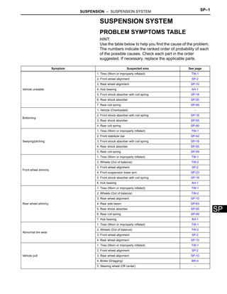
1. SUSPENSION – SUSPENSION SYSTEM SP–1
SP
SUSPENSION SYSTEM
PROBLEM SYMPTOMS TABLE
HINT:
Use the table below to help you find the cause of the problem.
The numbers indicate the ranked order of probability of each
of the possible causes. Check each part in the order
suggested. If necessary, replace the applicable parts.
Symptom Suspected area See page
Vehicle unstable
1. Tires (Worn or improperly inflated) TW-1
2. Front wheel alignment SP-2
3. Rear wheel alignment SP-10
4. Hub bearing AH-1
5. Front shock absorber with coil spring SP-18
6. Rear shock absorber SP-55
7. Rear coil spring SP-49
Bottoming
1. Vehicle (Overloaded) -
2. Front shock absorber with coil spring SP-18
3. Rear shock absorber SP-55
4. Rear coil spring SP-49
Swaying/pitching
1. Tires (Worn or improperly inflated) TW-1
2. Front stabilizer bar SP-42
3. Front shock absorber with coil spring SP-18
4. Rear shock absorber SP-55
5. Rear coil spring SP-49
Front wheel shimmy
1. Tires (Worn or improperly inflated) TW-1
2. Wheels (Out of balance) TW-2
3. Front wheel alignment SP-2
4. Front suspension lower arm SP-23
5. Front shock absorber with coil spring SP-18
6. Hub bearing AH-1
Rear wheel shimmy
1. Tires (Worn or improperly inflated) TW-1
2. Wheels (Out of balance) TW-2
3. Rear wheel alignment SP-10
4. Rear axle beam SP-63
5. Rear shock absorber SP-55
6. Rear coil spring SP-49
7. Hub bearing AH-1
Abnormal tire wear
1. Tires (Worn or improperly inflated) TW-1
2. Wheels (Out of balance) TW-2
3. Front wheel alignment SP-2
4. Rear wheel alignment SP-10
Vehicle pull
1. Tires (Worn or improperly inflated) TW-1
2. Front wheel alignment SP-2
3. Rear wheel alignment SP-10
4. Brake (Dragging) BR-4
5. Steering wheel (Off center) -
2. SP–2 SUSPENSION – FRONT WHEEL ALIGNMENT
SP
FRONT WHEEL ALIGNMENT
ADJUSTMENT
1. INSPECT TIRES (See page TW-1)
2. MEASURE VEHICLE HEIGHT
(a) Hatch back:
Vehicle height
Measuring points:
A:
Ground clearance of front wheel center
B:
Ground clearance of lower arm set front bolt
center
C:
Ground clearance of rear wheel center
D:
Ground clearance of axle beam set bolt
center
NOTICE:
Before inspecting the wheel alignment, check
the vehicle height.
HINT:
Bounce the vehicle up and down at the corners to
stabilize the suspension before inspecting the
vehicle height.
(b) Sedan:
Vehicle height
Measuring points:
A:
Ground clearance of front wheel center
B:
Ground clearance of lower arm set front bolt
center
C:
Ground clearance of rear wheel center
D:
Ground clearance of axle beam set bolt
center
NOTICE:
Before inspecting the wheel alignment, check
the vehicle height.
Front: Rear:
A
B
C
D
C106034E01
Destination A-B C-D
Except for Rough Road
Package
88 mm
(3.46 in.)
20 mm
(0.79 in.)
Rough Road Package
68 mm
(2.68 in.)
0 mm
(0 in.)
A
B
C
D
Front: Rear:
C132096E01
Destination A-B C-D
Except for Rough Road
Package
87 mm
(3.43 in.)
16 mm
(0.63 in.)
Rough Road Package
67 mm
(2.64 in.)
-2 mm
(-0.08 in.)
3. SUSPENSION – FRONT WHEEL ALIGNMENT SP–3
SP
HINT:
Bounce the vehicle up and down at the corners to
stabilize the suspension before inspecting the
vehicle height.
3. INSPECT TOE-IN
Toe-in:
Hatchback
Sedan
HINT:
Only measure C-D when A+B can not be measured.
If the toe-in is not within the specified value, adjust it at
the rack ends.
4. ADJUST TOE-IN
(a) Measure the thread lengths of the right and left rack
ends.
Standard:
Difference in thread length of 1.5 mm (0.059
in.) or less
(b) Remove the rack boot set clips.
(c) Loosen the tie rod end lock nuts.
(d) Adjust the rack ends if the difference in thread
length between the right and left rack ends is not
within the specified range.
(1) Extend the shorter rack end if the measured
toe-in deviates toward the outer-side.
(2) Shorten the longer rack end if the measured
toe-in deviates toward the inner-side.
(e) Turn the right and left rack ends by an equal amount
to adjust the toe-in.
HINT:
Try to adjust the toe-in to the center of the specified
range.
(f) Make sure that the lengths of the right and left rack
ends are the same.
Toe-in
(g) Tighten the tie rod end lock nuts to the specified
torque.
Torque: 75 N*m (760 kgf*cm, 55 ft.*lbf)
A B
D
Front
C
SA03213E02
A+B C-D
0°09' +- 0°13'
(0.15° +- 0.22°)
1.5 +- 2.0 mm
(0.06 +- 0.08 in.)
A+B C-D
0°12' +- 0°06'
(0.20° +- 0.10°)
2.0 +- 2.0 mm
(0.08 +- 0.08 in.)
C106036
Body Type Toe-in
Hatchback 1.5 +- 1.0 mm (0.06 +- 0.04 in.)
Sedan 2.0 +- 1.0 mm (0.08 +- 0.04 in.)
4. SP–4 SUSPENSION – FRONT WHEEL ALIGNMENT
SP
NOTICE:
Provisionally tighten the lock nut while holding
the hexagonal part of the steering rack end so
that the lock nut and the steering rack end do
not turn together. Hold the width across flat of
the tie rod end and tighten the lock nut.
(h) Place the boots on the seats.
(i) Using pliers, install the clip as shown in the
illustration.
NOTICE:
Make sure that the boots are not twisted.
5. INSPECT WHEEL TURNING ANGLE
(a) Fully turn the steering wheel left and right, and
measure the wheel turning angle.
Wheel turning angle
If the right and left inside wheel angles are not within
the specified range, check the right and left rack end
lengths.
6. INSPECT CAMBER, CASTER AND STEERING AXIS
INCLINATION
(a) Put the front wheel on the center of the alignment
tester.
(b) Remove the wheel cap.
(c) Set the camber-caster-steering axis inclination
gauge at the center of the axle hub or drive shaft.
(d) Inspect the camber, caster and steering axis
inclination.
Camber, caster and steering axis inclination:
Hatchback
Rear Side
Front Side
Upper Side
54°30’
180q
C106037E01
A B B A
Front
A: Inside
B: Outside
SA00028E05
Destination Inside Wheel
Outside Wheel
(Reference)
Except for Rough Road Package
40°57' +- 2°
(40.95° +- 2°)
35°17'
(35.29°)
Rough Road Package
41°22' +- 2°
(41.37° +- 2°)
35°45'
(35.75°)
Alignment
Tester
Gauge
Z003382E04
Destination Camber Caster
Steering Axis Inclination
(Reference)
Except for Rough Road
Package
-0°10' +- 45'
(-0.17°+- 0.75°)
4°46' +- 45'
(4.77°+- 0.75°)
11°18'
(11.30°)
5. SUSPENSION – FRONT WHEEL ALIGNMENT SP–5
SP
Sedan
NOTICE:
• Perform the inspection while the vehicle is
empty (without a spare tire or tools on board).
• The tolerance for the difference between the
left and right wheels is 30' (0.5°) or less for
both the camber and caster.
(e) Remove the camber-caster-steering axis inclination
gauge and attachment.
(f) Install the wheel cap.
If the caster and steering axis inclination are not
within the specified values after the camber has
been correctly adjusted, recheck the suspension
parts for damage and wear.
7. ADJUST CAMBER
NOTICE:
Inspect the toe-in after the camber has been
adjusted.
(a) Remove the front wheel.
(b) w/ ABS:
(1) Remove the bolt and separate the speed
sensor and flexible hose.
(c) Remove the 2 nuts on the lower side of the shock
absorber.
HINT:
Keep the bolt from rotating while loosening and
removing the nuts.
(d) Clean the installation surfaces of the shock
absorber and steering knuckle.
(e) Provisionally install the 2 nuts (Step A).
Rough Road Package
0°06' +- 45'
(0.10°+- 0.75°)
4°27' +- 45'
(4.45°+- 0.75°)
10°47'
(10.78°)
Destination Camber Caster
Steering Axis Inclination
(Reference)
Destination Camber Caster
Steering Axis Inclination
(Reference)
Except for Rough Road
Package
-0°10' +- 45'
(-0.17°+- 0.75°)
4°39' +- 45'
(4.65°+- 0.75°)
11°16'
(11.27°)
Rough Road Package
0°06' +- 45'
(0.10°+- 0.75°)
4°23' +- 45'
(4.38°+- 0.75°)
10°47'
(10.78°)
C125274
C125275
6. SP–6 SUSPENSION – FRONT WHEEL ALIGNMENT
SP
(f) Fully push or pull the axle hub in the direction of the
required adjustment (Step B).
(g) Tighten the 2 nuts.
Torque: 164 N*m (1,672 kgf*cm, 121 ft.*lbf)
HINT:
Keep the bolt from rotating while loosening and
removing the nuts.
(h) w/ ABS:
(1) Install the flexible hose and speed sensor with
the bolt.
Torque: 29 N*m (300 kgf*cm, 22 ft.*lbf)
NOTICE:
Install the flexible hose and speed sensor
without twisting them.
(i) Install the front wheel.
Torque: 103 N*m (1,050 kgf*cm, 76 ft.*lbf)
(j) Check the camber.
If the measured value is not within the specification,
calculate the required adjustment amount using the
formula below.
(Camber adjustment amount) = Center of specified
range - Measured value
Check the combination of installed bolts. Select
appropriate bolts from the table below to adjust the
camber to within the specified range.
HINT:
Try to adjust the camber to the center of the
specified range.
(-) (+)
C110325E01
C125275
C125274
1
2
C116741E02
Move axle toward (+) in step (B)
Refer to table (1) (Move axle toward
positive side)
Move axle toward (-) in step (B)
Refer to table (2) (Move axle toward
negative side)
7. SUSPENSION – FRONT WHEEL ALIGNMENT SP–7
SP
(k) Table (1) (Move the axle toward the positive side).
Installed
Bolt
Adjusting
Value
1
1
2
2
Table (1) (Move the axle toward the positive side)
Selected Bolt Combination
G
G
G
G
G
G
A
A
A
A
A
B
B
B
B
B
B
C
C
C
C
C
C
A
C
G
B
D
D
D
D
D
D
D
E
E
E
E
E
E
E
F
F
F
F
F
F
F
A
-1° 30’ to -1° 15’
-1° 15’ to -1° 00’
-1° 00’ to -0° 45’
-0° 45’ to -0° 30’
-0° 30’ to -0° 15’
-0° 15’ to 0°
0° to 0° 15’
0° 15’ to 0° 30’
0° 30’ to 0° 45’
0° 45’ to 1° 00’
1° 00’ to 1° 15’
1° 15’ to 1° 30’
90109-
15001
90109-
15001
90109-
15001
90109-
15001
90109-
15002
90109-
15003
90109-
15004
90109-
15004
90109-
15004
90109-
15004
90109-
15004
90109-
15003
90109-
15002
90109-
15001
90109-
15001
90109-
15002
90109-
15003
90109-
15004
90109-
15001
90109-
15001
90109-
15002
90109-
15001
90109-
15001
90109-
15004
90109-
15004
90109-
15004
90109-
15004
90109-
15003
C111317E07
8. SP–8 SUSPENSION – FRONT WHEEL ALIGNMENT
SP
(l) Table (2) (Move the axle toward the negative side).
The body and suspension may be damaged if the
camber is not correctly adjusted in accordance with
the above table.
NOTICE:
Replace the nut with a new one when replacing
the bolt.
Installed
Bolt
Adjusting
Value
1
1
2
2
Table (2) (Move the axle toward the negative side)
Selected Bolt Combination
B
C
D
E
F
G
G
G
G
G
G
C
C
C
C
C
A
A
A
A
A
A
F
F
F
F
F
B
B
B
B
B
E
E
E
E
E
D
D
D
D
D
-1° 30’ to -1° 15’
-1° 15’ to -1° 00’
-1° 00’ to -0° 45’
-0° 45’ to -0° 30’
-0° 30’ to -0° 15’
-0° 15’ to 0°
0° to 0°15’
0° 15’ to 0° 30’
0° 30’ to 0° 45’
0° 45’ to 1° 00’
1° 00’ to 1° 15’
1° 15’ to 1° 30’
A B C D E F G
90109-
15001
90109-
15003
90109-
15004
90109-
15001
90109-
15001
90109-
15001
90109-
15002
90109-
15001
90109-
15002
90109-
15003
90109-
15004
90109-
15004
90109-
15004
90109-
15004
90109-
15004
90109-
15001
90109-
15002
90109-
15003
90109-
15001
90109-
15001
90109-
15001
90109-
15002
90109-
15003
90109-
15004
90109-
15004
90109-
15004
90109-
15004
90109-
15001
C111317E08
9. SUSPENSION – FRONT WHEEL ALIGNMENT SP–9
SP
(m) Repeat the steps mentioned above. At step (A),
replace 1or 2 selected bolts.
HINT:
Replace one bolt at a time when replacing 2 bolts.
10. Thank you very much for
your reading. Please Click
Here. Then Get COMPLETE
MANUAL. NO WAITING
NOTE:
If there is no response to
click on the link above,
please download the PDF
document first and then
click on it.
11. SP–10 SUSPENSION – REAR WHEEL ALIGNMENT
SP
REAR WHEEL ALIGNMENT
INSPECTION
1. INSPECT TIRES (See page TW-1)
2. MEASURE VEHICLE HEIGHT (See page SP-2)
3. INSPECT TOE-IN
Toe-in:
Hatchback
Sedan
HINT:
Only measure C-D when A+B can not be measured.
4. INSPECT CAMBER
(a) Install the camber-caster-kingpin gauge and
position the rear wheel on the alignment tester.
(b) Inspect the camber.
Camber:
Hatchback
Sedan
A B
D
Front
C
SA03213E02
Destination Tire Size A+B C-D
Except for Rough Road
Package
175/65R14
0°17' +- 0°20'
(0.28°+- 0.33°)
2.8 +- 3.0 mm
(0.11 +- 0.12 in.)
185/60R15
0°17' +- 0°20'
(0.28°+- 0.33°)
2.9 +- 3.0 mm
(0.11 +- 0.12 in.)
Rough Road Package
175/65R14
0°13' +- 0°20'
(0.22°+- 0.33°)
2.2 +- 3.0 mm
(0.09 +- 0.12 in.)
185/60R15
0°13' +- 0°20'
(0.22°+- 0.33°)
2.2 +- 3.0 mm
(0.09 +- 0.12 in.)
Destination Tire Size A+B C-D
Except for Rough Road
Package
175/65R14
0°17' +- 0°20'
(0.28°+- 0.33°)
2.8 +- 3.0 mm
(0.11 +- 0.12 in.)
185/60R15
0°17' +- 0°20'
(0.28°+- 0.33°)
2.9 +- 3.0 mm
(0.11 +- 0.12 in.)
Rough Road Package
175/65R14
0°13' +- 0°20'
(0.22°+- 0.33°)
2.1 +- 3.0 mm
(0.08 +- 0.12 in.)
185/60R15
0°13' +- 0°20'
(0.22°+- 0.33°)
2.2 +- 3.0 mm
(0.09 +- 0.12 in.)
Destination Camber
Except for Rough Road Package
-0°57' +- 45'
(-0.95°+- 0.75°)
Rough Road Package
-0°54' +- 45'
(-0.90°+- 0.75°)
12. SUSPENSION – REAR WHEEL ALIGNMENT SP–11
SP
NOTICE:
The tolerance for the difference between the left
and right wheels is 30' (0.5°) or less for both
cambers.
If the camber is not within the specified range,
inspect the suspension parts and replace them if
necessary.
Destination Camber
Except for Rough Road Package
-0°56' +- 45'
(-0.93°+- 0.75°)
Rough Road Package
-0°54' +- 45'
(-0.90°+- 0.75°)
13. SP–12 SUSPENSION – FRONT SHOCK ABSORBER WITH COIL SPRING
SP
SUSPENSION & AXLE
SUSPENSION
FRONT SHOCK ABSORBER WITH COIL SPRING
COMPONENTS
FRONT WIPER ARM HEAD CAP
FRONT WIPER
MOTOR AND LINK
FRONT WIPER
ARM HEAD CAP
FRONT WIPER ARM AND
BLADE ASSEMBLY LH
FRONT WIPER ARM AND
BLADE ASSEMBLY RH
N*m (kgf*cm, ft*lbf) :Specified torque
5.5 (56, 49 in.*lbf)
26 (265, 19)
26 (265, 19)
5.5 (56, 49 in.*lbf)
x9
6.5 (66, 58 in.*lbf)
CLIP
CLIP
CLIP
for Hatchback:
NO. 1 COWL TOP VENTILATOR
LOUVER CENTER
COWL TOP VENTILATOR
LOUVER LH
COWL TOP VENTILATOR
LOUVER SUB-ASSEMBLY
HOOD TO COWL TOP SEAL
COWL TO REGISTER DUCT SUB-ASSEMBLY
OUTER COWL TOP PANEL
C116866E10
14. SUSPENSION – FRONT SHOCK ABSORBER WITH COIL SPRING SP–13
SP
6.5 (66, 58 in.*lbf)
for Sedan:
N*m (kgf*cm, ft*lbf) : Specified torque
x2
x8
5.5 (56, 49 in.*lbf)
x3
26 (265, 19)
INNER COWL TOP
TO COWL BRACE
26 (265, 19)
COWL SIDE VENTILATOR
SUB-ASSEMBLY LH
COWL SIDE
VENTILATOR
SUB-ASSEMBLY
RH
COWL TOP VENTILATOR
LOUVER SUB-ASSEMBLY
FRONT AIR
SHUTTER
SEAL
FRONT WIPER ARM AND
BLADE ASSEMBLY LH
FRONT WIPER ARM AND
BLADE ASSEMBLY RH
FRONT WIPER ARM HEAD CAP
FRONT WIPER MOTOR AND LINK
OUTER COWL
TOP PANEL
FRONT WIPER ARM
HEAD CAP
A133320E07
15. SP–14 SUSPENSION – FRONT SHOCK ABSORBER WITH COIL SPRING
SP
FRONT FLEXIBLE HOSE
FRONT SHOCK ABSORBER
WITH COIL SPRING
FRONT STABILIZER LINK
ASSEMBLY
FRONT SUSPENSION SUPPORT DUST COVER
FRONT SPEED SENSOR
FRONT NO. 2 SUSPENSION SUPPORT
29 (300, 22)
164 (1,672, 121)
74 (755, 55)
55 (561, 41)
N*m (kgf*cm, ft*lbf) : Specified torque
Non-reusable part
w/ ABS:
C121847E02
16. SUSPENSION – FRONT SHOCK ABSORBER WITH COIL SPRING SP–15
SP
FRONT UPPER COIL
SPRING INSULATOR
FRONT SUPPORT TO FRONT
SHOCK ABSORBER NUT
STRUT MOUNTING
BEARING
FRONT SPRING BUMPER
FRONT UPPER COIL
SPRING SEAT
FRONT SUSPENSION
SUPPORT SUB-ASSEMBLY
FRONT COIL SPRING
33 (340, 25)
N*m (kgf*cm, ft*lbf) : Specified torque
Non-reusable part
FRONT SHOCK ABSORBER
C106043E03