Downloaded 159 times
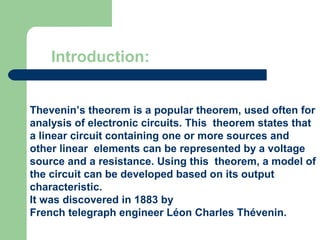
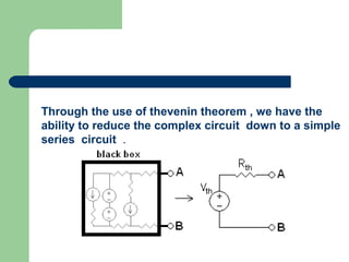
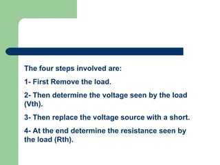
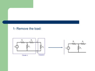
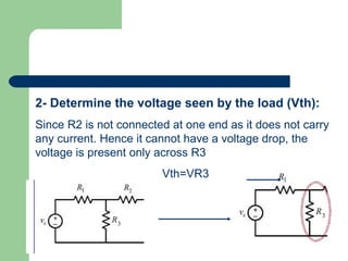
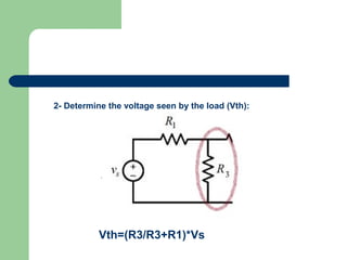
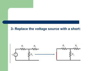
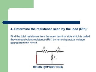
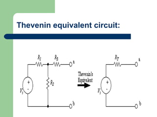


Thevenin's theorem states that a linear circuit containing sources and elements can be represented by a voltage source and resistance. It allows a complex circuit to be reduced to a simple series circuit. The four steps are: 1) remove the load, 2) determine voltage seen by load (Vth), 3) replace voltage source with short, 4) determine resistance seen by load (Rth). Using these steps, any linear circuit can be converted into a Thevenin equivalent circuit with a single voltage source and resistance.


![Circuit Network Analysis - [Chapter1] Basic Circuit Laws](https://cdn.slidesharecdn.com/ss_thumbnails/ch1-150613063856-lva1-app6892-thumbnail.jpg?width=640&height=640&fit=bounds)


