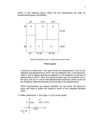
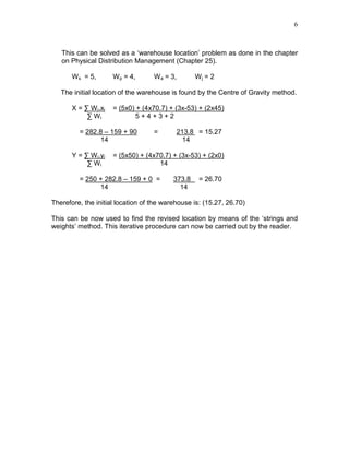
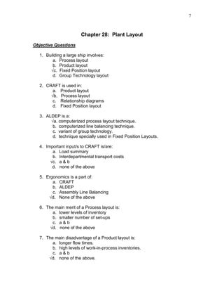
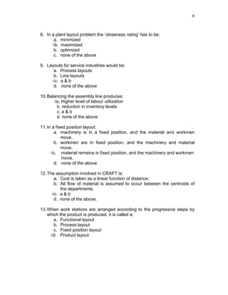
CHAPTER 28: Plant Layout
Responses to Questions
1. A layout is an expression of the health of flow of materials/men in a
plant/workplace. A good layout has no congestions of materials/men, no
confusion, and no damage/spoilage of materials; it has minimal handling
and storage costs, and helps production by allowing a smooth flow of
inputs. A good layout spells productivity.
2. Good layout principles are applicable anywhere and certainly so in
designing an office. Office is a place where people and information keep
flowing; the output is the decisions made by the managers and the staff.
The layout should be conductive to a free flow of information and for the
movement and communication of/between people.
3. Technology of materials handling, technology of communication, and
technology of movement of people has obvious impact on the layout of the
work place. Overhead cranes, conveyor belts and fork-lift trucks have
obviously different layout needs. Similarly, paper work, electronic
communication, telephone/fax communication and personal
communication have each different needs of office layout.
4. CRAFT is an efficient layout-design programme which solves problems in
a short time. It is a computer-based programme; this fact speaks for its
merits and limitations. The soft data and soft decisions like human
relations, future expansions etc are not explicitly taken into account.
5. Nearness diagram and the weightages given therein can be used in a
suitable computer algorithm to design the relative layouts of the different
departments or work-places. Load summary uses actual data but
nearness can only be expressed in ‘ratings’; so this approach has its
limitations.
6. Ergonomics requires certain spaces for a comfortable movement of the
human limbs. Therefore, ergonomic requirements are and should be an
integral part of any plant layout.
7. Group Technology (GT) is used where products can be seen as ‘families’
of products from the processing point of view. GT kind of layout can
improve plant productivities substantially. More on GT is available in the
next chapter (Chapter 29).
8. Flexible Manufacturing System (FMS) combines computer controls, NC
machines and GT to make a manufacturing system that is flexible in terms
of the variety of products, on time production and on demand production.
2
FMS requires a GT layout that is also suitable for an automated
movement of materials, from one process to another and from warehouse
to process and back.
9. Different production scheduling system will result in different inventory on
the shop-floor. The WIP may especially vary widely. To that extent, the
scheduling has a bearing on layout that needs to create spaces for the
work-in-process.
10.The basic input to this process layout problem is the load summary. The
latter can be obtained by combining the product sequences given with the
given monthly production volume. For example the frequency of transport
between the departments A and C is found as follows.
The flow A C occurs for products P and V. Product P is produced in the
volume of 140 units and product V in 90 units. Thus, the flow A C can be
considered to be (140 +90 =) 230 units per month.
Based on similar considerations the following load summary matrix is arrived
at.
Load Summary
A B C D E F
A 75
(75)
140 + 90
(230)
175 + 75
+100
(350)
(0) (O)
B
(0)
50 + 115
(165)
75
(75)
115
(115)
C 140 + 90
(230) (0)
175
(175)
D 140 + 50 + 115 +
100+ 90
(495)
175
(175)
E 140 +
100 + 90
(330)
F
We have clubbed together the to-and-fro movements between any pair of
departments. For instance, all the movements A–D and D-A are put together
in the above load summary (175 is for A-D, 75 is for D-A and 100 is for A-D,
giving a total of 350).
3
Based on the load summary, we can rank the closeness requirements of any
pair of departments as:
Pairs of Depts. Load Frequency Rank
D and E
D and A
E and F
D and C
A and C
C and F
D and F
B and D
B and A
B and E
495
350
330
230
230
175
175
165
75
75
1
2
3
4
4
6
6
8
9
9
(Note: Rank 1 means it is highly preferable to keep this pair of departments
close together. As the ranks increase, it shows less and less preference for
closeness.)
Based on the rankings given above, the departments can be arranged on a
grid, as per figure. (The flows between the departments are also shown).
In the above figure we notice that there is one flow between non-adjacent
departments. This non-adjacent flow is between the departments C and F
and is of a significant magnitude of 175 units. We shall try to improve the
layout by reducing this flow. As a first step we exchange the places of the
departments B and F on the grid. The resultant layout and the flows are
shown in the following figure.
4
This is an improvement over the earlier layout because the non-adjacent
flows are now 75 (an improvement by 100 units). We also notice that no
further improvement is possible.
The layout on the grid is now transformed into actual areas by putting the
department squares on the grid, as in the figure given below.
The departments are to be arranged in the available total space of 100 x 100
m. keeping the individual department areas intact, the arrangement can be as
5
shown in the following figure. (Note that the departments are kept as
squarish/rectangular as possible).
25 37.5 37.5
40 A D E
53.33
60 C F D 46.67
25 21.42 53 .58
Note: All dimensions are in metres (not to exact scale)
Final Layout
It should be noted that in the grid format the departments F and E are
adjacent and departments A and F are non-adjacent. But, in the layout-to-
scale F and E appear perhaps as adjacent or non-adjacent as the pair of
departments A and F. Now, the layout-to-scale may be evaluated not in
the grid units but in actual inter-departmental distances (which could be
the rectilinear distances between the centroids of the departments).
While improvements are always possible, we can leave the layout as
given and hope to obtain fair results in terms of the materials handling
costs.
11.Make Lakshmipur ‘L’ the origin i.e. (0,0) on the graph.
. P
S .(0,50) (70.7, 70.7)
L .J
(45,0)
(-53, -53)
. A
6
This can be solved as a ‘warehouse location’ problem as done in the chapter
on Physical Distribution Management (Chapter 25).
Ws = 5, Wp = 4, Wa = 3, Wj = 2
The initial location of the warehouse is found by the Centre of Gravity method.
X = ∑ Wi.xi = (5x0) + (4x70.7) + (3x-53) + (2x45)
∑ Wi 5 + 4 + 3 + 2
= 282.8 – 159 + 90 = 213.8 = 15.27
14 14
Y = ∑ Wi.yi = (5x50) + (4x70.7) + (3x-53) + (2x0)
∑ Wi 14
= 250 + 282.8 – 159 + 0 = 373.8 = 26.70
14 14
Therefore, the initial location of the warehouse is: (15.27, 26.70)
This can be now used to find the revised location by means of the ‘strings and
weights’ method. This iterative procedure can now be carried out by the reader.
7
Chapter 28: Plant Layout
Objective Questions
1. Building a large ship involves:
a. Process layout
b. Product layout
√c. Fixed Position layout
d. Group Technology layout
2. CRAFT is used in:
a. Product layout
√b. Process layout
c. Relationship diagrams
d. Fixed Position layout
3. ALDEP is a:
√a. computerized process layout technique.
b. computerized line balancing technique.
c. variant of group technology.
d. technique specially used in Fixed Position Layouts.
4. Important input/s to CRAFT is/are:
a. Load summary
b. Interdepartmental transport costs
√c. a & b
d. none of the above
5. Ergonomics is a part of:
a. CRAFT
b. ALDEP
c. Assembly Line Balancing
√d. None of the above
6. The main merit of a Process layout is:
a. lower levels of inventory
b. smaller number of set-ups
c. a & b
√d. none of the above
7. The main disadvantage of a Product layout is:
a. longer flow times.
b. high levels of work-in-process inventories.
c. a & b
√d. none of the above.
8
8. In a plant layout problem the ‘closeness rating’ has to be:
a. minimized
√b. maximized
b. optimized
c. none of the above
9. Layouts for service industries would be:
a. Process layouts
b. Line layouts
√c. a & b
d. none of the above
10.Balancing the assembly line produces:
√a. Higher level of labour utilization
b. reduction in inventory levels
c. a & b
d. none of the above
11.In a fixed position layout:
a. machinery is in a fixed position, and the material and workmen
move.
b. workmen are in fixed position, and the machinery and material
move.
√c. material remains in fixed position, and the machinery and workmen
move.
d. none of the above
12.The assumption involved in CRAFT is:
a. Cost is taken as a linear function of distance.
b. All flow of material is assumed to occur between the centroids of
the departments.
√c. a & b
d. none of the above.
13.When work stations are arranged according to the progressive steps by
which the product is produced, it is called a:
a. Functional layout
b. Process layout
c. Fixed position layout
√d. Product layout

Production & Operation Management Chapter28[1]

  • 1.
    CHAPTER 28: PlantLayout Responses to Questions 1. A layout is an expression of the health of flow of materials/men in a plant/workplace. A good layout has no congestions of materials/men, no confusion, and no damage/spoilage of materials; it has minimal handling and storage costs, and helps production by allowing a smooth flow of inputs. A good layout spells productivity. 2. Good layout principles are applicable anywhere and certainly so in designing an office. Office is a place where people and information keep flowing; the output is the decisions made by the managers and the staff. The layout should be conductive to a free flow of information and for the movement and communication of/between people. 3. Technology of materials handling, technology of communication, and technology of movement of people has obvious impact on the layout of the work place. Overhead cranes, conveyor belts and fork-lift trucks have obviously different layout needs. Similarly, paper work, electronic communication, telephone/fax communication and personal communication have each different needs of office layout. 4. CRAFT is an efficient layout-design programme which solves problems in a short time. It is a computer-based programme; this fact speaks for its merits and limitations. The soft data and soft decisions like human relations, future expansions etc are not explicitly taken into account. 5. Nearness diagram and the weightages given therein can be used in a suitable computer algorithm to design the relative layouts of the different departments or work-places. Load summary uses actual data but nearness can only be expressed in ‘ratings’; so this approach has its limitations. 6. Ergonomics requires certain spaces for a comfortable movement of the human limbs. Therefore, ergonomic requirements are and should be an integral part of any plant layout. 7. Group Technology (GT) is used where products can be seen as ‘families’ of products from the processing point of view. GT kind of layout can improve plant productivities substantially. More on GT is available in the next chapter (Chapter 29). 8. Flexible Manufacturing System (FMS) combines computer controls, NC machines and GT to make a manufacturing system that is flexible in terms of the variety of products, on time production and on demand production.
  • 2.
    2 FMS requires aGT layout that is also suitable for an automated movement of materials, from one process to another and from warehouse to process and back. 9. Different production scheduling system will result in different inventory on the shop-floor. The WIP may especially vary widely. To that extent, the scheduling has a bearing on layout that needs to create spaces for the work-in-process. 10.The basic input to this process layout problem is the load summary. The latter can be obtained by combining the product sequences given with the given monthly production volume. For example the frequency of transport between the departments A and C is found as follows. The flow A C occurs for products P and V. Product P is produced in the volume of 140 units and product V in 90 units. Thus, the flow A C can be considered to be (140 +90 =) 230 units per month. Based on similar considerations the following load summary matrix is arrived at. Load Summary A B C D E F A 75 (75) 140 + 90 (230) 175 + 75 +100 (350) (0) (O) B (0) 50 + 115 (165) 75 (75) 115 (115) C 140 + 90 (230) (0) 175 (175) D 140 + 50 + 115 + 100+ 90 (495) 175 (175) E 140 + 100 + 90 (330) F We have clubbed together the to-and-fro movements between any pair of departments. For instance, all the movements A–D and D-A are put together in the above load summary (175 is for A-D, 75 is for D-A and 100 is for A-D, giving a total of 350).
  • 3.
    3 Based on theload summary, we can rank the closeness requirements of any pair of departments as: Pairs of Depts. Load Frequency Rank D and E D and A E and F D and C A and C C and F D and F B and D B and A B and E 495 350 330 230 230 175 175 165 75 75 1 2 3 4 4 6 6 8 9 9 (Note: Rank 1 means it is highly preferable to keep this pair of departments close together. As the ranks increase, it shows less and less preference for closeness.) Based on the rankings given above, the departments can be arranged on a grid, as per figure. (The flows between the departments are also shown). In the above figure we notice that there is one flow between non-adjacent departments. This non-adjacent flow is between the departments C and F and is of a significant magnitude of 175 units. We shall try to improve the layout by reducing this flow. As a first step we exchange the places of the departments B and F on the grid. The resultant layout and the flows are shown in the following figure.
  • 4.
    4 This is animprovement over the earlier layout because the non-adjacent flows are now 75 (an improvement by 100 units). We also notice that no further improvement is possible. The layout on the grid is now transformed into actual areas by putting the department squares on the grid, as in the figure given below. The departments are to be arranged in the available total space of 100 x 100 m. keeping the individual department areas intact, the arrangement can be as
  • 5.
    5 shown in thefollowing figure. (Note that the departments are kept as squarish/rectangular as possible). 25 37.5 37.5 40 A D E 53.33 60 C F D 46.67 25 21.42 53 .58 Note: All dimensions are in metres (not to exact scale) Final Layout It should be noted that in the grid format the departments F and E are adjacent and departments A and F are non-adjacent. But, in the layout-to- scale F and E appear perhaps as adjacent or non-adjacent as the pair of departments A and F. Now, the layout-to-scale may be evaluated not in the grid units but in actual inter-departmental distances (which could be the rectilinear distances between the centroids of the departments). While improvements are always possible, we can leave the layout as given and hope to obtain fair results in terms of the materials handling costs. 11.Make Lakshmipur ‘L’ the origin i.e. (0,0) on the graph. . P S .(0,50) (70.7, 70.7) L .J (45,0) (-53, -53) . A
  • 6.
    6 This can besolved as a ‘warehouse location’ problem as done in the chapter on Physical Distribution Management (Chapter 25). Ws = 5, Wp = 4, Wa = 3, Wj = 2 The initial location of the warehouse is found by the Centre of Gravity method. X = ∑ Wi.xi = (5x0) + (4x70.7) + (3x-53) + (2x45) ∑ Wi 5 + 4 + 3 + 2 = 282.8 – 159 + 90 = 213.8 = 15.27 14 14 Y = ∑ Wi.yi = (5x50) + (4x70.7) + (3x-53) + (2x0) ∑ Wi 14 = 250 + 282.8 – 159 + 0 = 373.8 = 26.70 14 14 Therefore, the initial location of the warehouse is: (15.27, 26.70) This can be now used to find the revised location by means of the ‘strings and weights’ method. This iterative procedure can now be carried out by the reader.
  • 7.
    7 Chapter 28: PlantLayout Objective Questions 1. Building a large ship involves: a. Process layout b. Product layout √c. Fixed Position layout d. Group Technology layout 2. CRAFT is used in: a. Product layout √b. Process layout c. Relationship diagrams d. Fixed Position layout 3. ALDEP is a: √a. computerized process layout technique. b. computerized line balancing technique. c. variant of group technology. d. technique specially used in Fixed Position Layouts. 4. Important input/s to CRAFT is/are: a. Load summary b. Interdepartmental transport costs √c. a & b d. none of the above 5. Ergonomics is a part of: a. CRAFT b. ALDEP c. Assembly Line Balancing √d. None of the above 6. The main merit of a Process layout is: a. lower levels of inventory b. smaller number of set-ups c. a & b √d. none of the above 7. The main disadvantage of a Product layout is: a. longer flow times. b. high levels of work-in-process inventories. c. a & b √d. none of the above.
  • 8.
    8 8. In aplant layout problem the ‘closeness rating’ has to be: a. minimized √b. maximized b. optimized c. none of the above 9. Layouts for service industries would be: a. Process layouts b. Line layouts √c. a & b d. none of the above 10.Balancing the assembly line produces: √a. Higher level of labour utilization b. reduction in inventory levels c. a & b d. none of the above 11.In a fixed position layout: a. machinery is in a fixed position, and the material and workmen move. b. workmen are in fixed position, and the machinery and material move. √c. material remains in fixed position, and the machinery and workmen move. d. none of the above 12.The assumption involved in CRAFT is: a. Cost is taken as a linear function of distance. b. All flow of material is assumed to occur between the centroids of the departments. √c. a & b d. none of the above. 13.When work stations are arranged according to the progressive steps by which the product is produced, it is called a: a. Functional layout b. Process layout c. Fixed position layout √d. Product layout