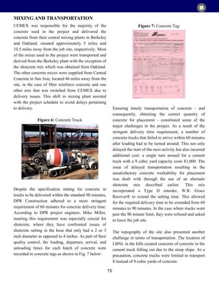
The high-level points are:
1) Four concrete mix designs were discussed in detail for the CRT Facility construction project: high early strength concrete, fiber reinforced concrete, shotcrete, and controlled density fill.
2) The mixes used various cement types, aggregates, fly ash, and chemical admixtures to achieve the required properties for different locations in the facility.
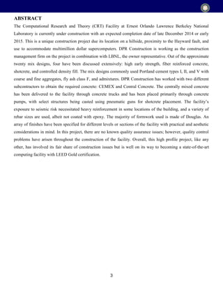
3) Unique aspects of the project included its hillside location near the Hayward fault, extensive foundation work, and a seismically isolated computing floor housing supercomputers.
![8
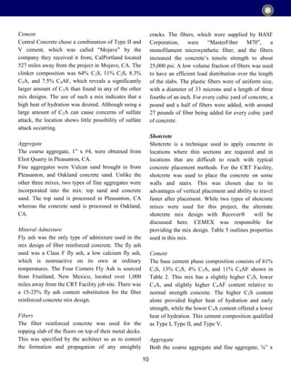
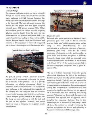
Chemical admixtures can have different purposes
depending on the type used. The types of chemical
admixtures used in this project are Type A water-
reducing, Type D water-reducing and retarding, and
air-entraining. All of the chemical admixtures used in
the project were manufactured and supplied by Grace
Construction Products, W.R. Grace & Co. - Conn.
(W.R. Grace) and formulated to comply with
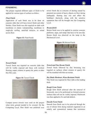
Specifications for Chemical Admixtures for
Concrete. W.R. Grace was located in Livermore, CA,
37 miles away from the project site. All of the
recommended dosages were followed.
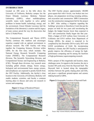
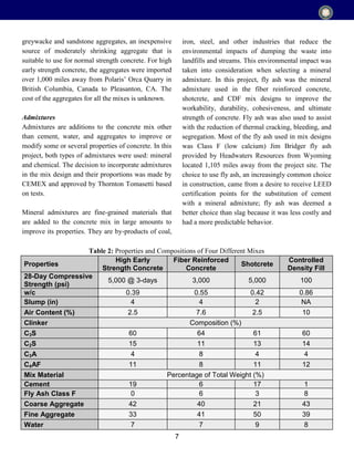
Table 2, on the previous page, summarizes details
provided by manufacturers and general contractor of
these four diverse mixes. This table allows for the
comparison of properties and compositions between
the mixes.
These four mixes and their individual properties are
discussed extensively as follows.
High Early Strength
High early strength concrete is the type of concrete
that develops relatively high compressive strength in
a shorter span of time when compared to normal
strength concrete. On occasions, this concrete can be
used to accelerate a project’s schedule. As a result of
the higher early compressive strength, loads can be
applied sooner to the casted concrete, and the next
dependent task in the schedule can commence. Most
of these mixes are more expensive than typical
concrete mixes.
In this project, high early strength concrete was used
for walls of the CRT Facility footings with tiebacks
that required a compressive strength of 3,000 psi
within 7 days, and slabs on deck. This section will
specifically cover high early strength concrete used
for walls, which did not use the concrete properties
for its high early strength but rather used it for
scheduling purposes. The use of this concrete mix
design allowed for formwork to be removed after one
day, in addition to allowing the concrete to achieve
60-70% compressive strength gain in four days.
The concrete was specified to achieve a compressive
strength of 5,000 psi at three days [Table 2], after
which a compressive strength test was conducted to
verify this before proceeding with formwork
removal. The water-to-cement ratio, at 0.39
[Table 2], was relatively low compared to other
mixes, which can help assist with its high strength.
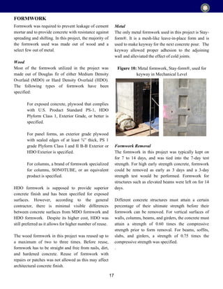
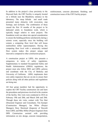
Table 3, below, describes the material composition of
high early strength concrete mix design.
Cement
The composition of C3S in cement used in the project
Material Description Source Oz/yd Weight (lb)
Volume
(ft3
)
Cement Type I/II/V CEMEX - 776.0 3.95
Coarse
Aggregate
Orca ½” x #4
Polaris Minerals
Corp.
- 1750.0 9.70
Fine Aggregate
Orca Concrete
Sand
Polaris Minerals
Corp.
- 1365.2 7.87
Type A Water
Reducer
WRDA 64 W.R. Grace
2.0 – 4.0 oz/
cwt C
- -
Water - - 36.0 gal 300.4 4.81
Air - - - - 0.68
Table 3: Mix Design of High Early Strength Concrete](https://image.slidesharecdn.com/6034d923-56a6-4a0b-ae25-72d3442dca08-160526032746/85/CE-165-Report-Final-8-320.jpg)
![9
is somewhat high at 60% [Table 2], which assisted
with high early strength development. Although
sulfate resistance was not required for the concrete
walls, the mix contained less than 5% of C3A which
will provide high resistance against sulfate attacks.
Aggregates
Unlike the other mixes, aggregates in this mix were
from Orca Sand & Gravel in British Columbia,
Canada and supplied by Polaris Minerals Corp. ½” x
#4 gravel was used as coarse aggregate and concrete
sand was used as fine aggregate.
Mineral Admixture
No mineral admixtures were used in the high early
strength concrete mix, making it the only mix out of
the four discussed to not contain any fly ash. This is
because substitution of cement with fly ash will
reduce the amount of C3S in the mix, which is
responsible for high early strength development.
Although fly ash could be added instead of
substituted into the mix, this is likely not practical
since fly ash does not play an important role in high
early strength development and its addition would
increase costs without any energy savings.
Chemical Admixture
The high early strength was achieved by using a
Type A water-reducing admixture from Grace
Concrete Products, which produces concrete with 8-
10% less water. Since the amount of water reduction
is less than 15%, this admixture is simply a
plasticizer. This water-reducing admixture was used
to reduce the required amount of water, lowering the
water-to-cement ratio. This allowed for higher
strength without the addition of cement. The addition
of this admixture also increased the consistency of
the mix without the addition of cement, reducing the
amount of water needed for the same slump.
Concerns of corrosion from the use of admixtures is
eliminated through the use of this particular product,
which does not contain calcium chloride. For every
100 pounds of concrete, 3-6 ounces of the water-
reducing admixture was used.
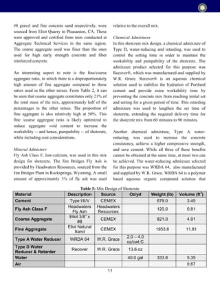
Fiber Reinforced Concrete
Fiber reinforcement was used as a means to reduce
shrinkage cracking that often occurs in slabs with
large exposed surfaces. The proper use of these fibers
makes for efficient load distribution, and is typically
cheaper than placing reinforcement or wiremesh that
may be susceptible to corrosion. Due to scheduling
problems, the fiber reinforced concrete mix could not
be brought in by CEMEX and was instead brought in
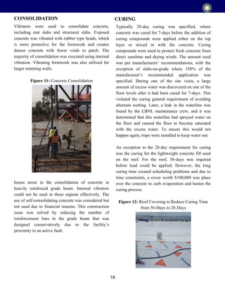
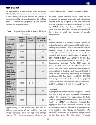
by Central Concrete from San Jose. Table 4, below,
describes the material composition of fiber reinforced
concrete mix design.
Material Description Source
lbs/cu
yd
Weight
(lb)
Volume
(ft3
)
Cement Type II/V CalPortland - 243.0 1.24
Fly Ash Class F Four Corners Flyash Salt River Materials - 243.0 1.59
Coarse Aggregate Eliot 1” x #4 CEMEX - 1675.0 10.02
Fine Aggregate
Top Sand
Vulcan Materials
Company
- 812.0 4.94
Fine Aggregate Oakland Concrete
Sand
Hanson Aggregates - 812.0 4.95
Fiber
Reinforcement
MasterFiber M 70 BASF
0.75-
1.50
- -
Water - - - 267.0 4.28
Table 4: Mix Design of Fiber Reinforced Concrete](https://image.slidesharecdn.com/6034d923-56a6-4a0b-ae25-72d3442dca08-160526032746/85/CE-165-Report-Final-9-320.jpg)