The document provides instructions for disassembling and assembling a recoil cylinder. Key steps include:
1. Removing the recoil cylinder and various components like bolts, guards, valves, seals, and pins.
2. Inspecting parts and cleaning components before assembly.
3. Reassembling the recoil cylinder by installing components in reverse order and applying lubricant and torque specifications. Tools are required for tasks like pushing/pulling parts.
Things to remember while upgrading the brakes of your carjennifermiller8137
Upgrading the brakes of your car? Keep these things in mind before doing so. Additionally, start using an OBD 2 GPS tracker so that you never miss a vehicle maintenance appointment. On top of this, a car GPS tracker will also let you master good driving habits that will let you increase the operational life of your car’s brakes.
What Exactly Is The Common Rail Direct Injection System & How Does It WorkMotor Cars International
Learn about Common Rail Direct Injection (CRDi) - the revolutionary technology that has made diesel engines more efficient. Explore its workings, advantages like enhanced fuel efficiency and increased power output, along with drawbacks such as complexity and higher initial cost. Compare CRDi with traditional diesel engines and discover why it's the preferred choice for modern engines.
𝘼𝙣𝙩𝙞𝙦𝙪𝙚 𝙋𝙡𝙖𝙨𝙩𝙞𝙘 𝙏𝙧𝙖𝙙𝙚𝙧𝙨 𝙞𝙨 𝙫𝙚𝙧𝙮 𝙛𝙖𝙢𝙤𝙪𝙨 𝙛𝙤𝙧 𝙢𝙖𝙣𝙪𝙛𝙖𝙘𝙩𝙪𝙧𝙞𝙣𝙜 𝙩𝙝𝙚𝙞𝙧 𝙥𝙧𝙤𝙙𝙪𝙘𝙩𝙨. 𝙒𝙚 𝙝𝙖𝙫𝙚 𝙖𝙡𝙡 𝙩𝙝𝙚 𝙥𝙡𝙖𝙨𝙩𝙞𝙘 𝙜𝙧𝙖𝙣𝙪𝙡𝙚𝙨 𝙪𝙨𝙚𝙙 𝙞𝙣 𝙖𝙪𝙩𝙤𝙢𝙤𝙩𝙞𝙫𝙚 𝙖𝙣𝙙 𝙖𝙪𝙩𝙤 𝙥𝙖𝙧𝙩𝙨 𝙖𝙣𝙙 𝙖𝙡𝙡 𝙩𝙝𝙚 𝙛𝙖𝙢𝙤𝙪𝙨 𝙘𝙤𝙢𝙥𝙖𝙣𝙞𝙚𝙨 𝙗𝙪𝙮 𝙩𝙝𝙚 𝙜𝙧𝙖𝙣𝙪𝙡𝙚𝙨 𝙛𝙧𝙤𝙢 𝙪𝙨.
Over the 10 years, we have gained a strong foothold in the market due to our range's high quality, competitive prices, and time-lined delivery schedules.
In this presentation, we have discussed a very important feature of BMW X5 cars… the Comfort Access. Things that can significantly limit its functionality. And things that you can try to restore the functionality of such a convenient feature of your vehicle.
5 Warning Signs Your BMW's Intelligent Battery Sensor Needs AttentionBertini's German Motors
IBS monitors and manages your BMW’s battery performance. If it malfunctions, you will have to deal with an array of electrical issues in your vehicle. Recognize warning signs like dimming headlights, frequent battery replacements, and electrical malfunctions to address potential IBS issues promptly.
Symptoms like intermittent starting and key recognition errors signal potential problems with your Mercedes’ EIS. Use diagnostic steps like error code checks and spare key tests. Professional diagnosis and solutions like EIS replacement ensure safe driving. Consult a qualified technician for accurate diagnosis and repair.
Why Is Your BMW X3 Hood Not Responding To Release CommandsDart Auto
Experiencing difficulty opening your BMW X3's hood? This guide explores potential issues like mechanical obstruction, hood release mechanism failure, electrical problems, and emergency release malfunctions. Troubleshooting tips include basic checks, clearing obstructions, applying pressure, and using the emergency release.
Comprehensive program for Agricultural Finance, the Automotive Sector, and Empowerment . We will define the full scope and provide a detailed two-week plan for identifying strategic partners in each area within Limpopo, including target areas.:
1. Agricultural : Supporting Primary and Secondary Agriculture
• Scope: Provide support solutions to enhance agricultural productivity and sustainability.
• Target Areas: Polokwane, Tzaneen, Thohoyandou, Makhado, and Giyani.
2. Automotive Sector: Partnerships with Mechanics and Panel Beater Shops
• Scope: Develop collaborations with automotive service providers to improve service quality and business operations.
• Target Areas: Polokwane, Lephalale, Mokopane, Phalaborwa, and Bela-Bela.
3. Empowerment : Focusing on Women Empowerment
• Scope: Provide business support support and training to women-owned businesses, promoting economic inclusion.
• Target Areas: Polokwane, Thohoyandou, Musina, Burgersfort, and Louis Trichardt.
We will also prioritize Industrial Economic Zone areas and their priorities.
Sign up on https://profilesmes.online/welcome/
To be eligible:
1. You must have a registered business and operate in Limpopo
2. Generate revenue
3. Sectors : Agriculture ( primary and secondary) and Automative
Women and Youth are encouraged to apply even if you don't fall in those sectors.
"Trans Failsafe Prog" on your BMW X5 indicates potential transmission issues requiring immediate action. This safety feature activates in response to abnormalities like low fluid levels, leaks, faulty sensors, electrical or mechanical failures, and overheating.
What Does the PARKTRONIC Inoperative, See Owner's Manual Message Mean for You...Autohaus Service and Sales
Learn what "PARKTRONIC Inoperative, See Owner's Manual" means for your Mercedes-Benz. This message indicates a malfunction in the parking assistance system, potentially due to sensor issues or electrical faults. Prompt attention is crucial to ensure safety and functionality. Follow steps outlined for diagnosis and repair in the owner's manual.
Fleet management these days is next to impossible without connected vehicle solutions. Why? Well, fleet trackers and accompanying connected vehicle management solutions tend to offer quite a few hard-to-ignore benefits to fleet managers and businesses alike. Let’s check them out!
Digital Fleet Management - Why Your Business Need It?
Caterpillar Cat D7E LGP TRACK-TYPE TRACTOR (Prefix TJA) Service Repair Manual (TJA00001 and up).pdf
1. Shutdown SIS
Previous Screen
Product: TRACK-TYPE TRACTOR
Model: D7E LGP TRACK-TYPE TRACTOR TJA
Configuration: D7E TRACK-TYPE TRACTOR LGP TJA00001-UP (MACHINE) POWERED BY C9.3 Engine
Disassembly and Assembly
D7E Track-Type Tractor Power Train
Media Number -KENR5606-03 Publication Date -01/12/2012 Date Updated -05/12/2012
i06007078
Recoil Cylinder - Disassemble
SMCS - 4151-015
Disassembly Procedure
Start By:
A. Remove the track adjuster and the recoil cylinder.
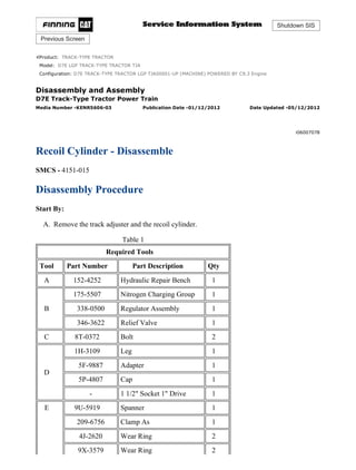
Table 1
Required Tools
Tool Part Number Part Description Qty
A 152-4252 Hydraulic Repair Bench 1
B
175-5507 Nitrogen Charging Group 1
338-0500 Regulator Assembly 1
346-3622 Relief Valve 1
C 8T-0372 Bolt 2
D
1H-3109 Leg 1
5F-9887 Adapter 1
5P-4807 Cap 1
- 1 1/2" Socket 1" Drive 1
E 9U-5919 Spanner 1
209-6756 Clamp As 1
4J-2620 Wear Ring 2
9X-3579 Wear Ring 2
1/10
D7E TRACK-TYPE TRACTOR LGP TJA00001-UP (MACHINE) POWERED BY C...
2021/8/27
https://127.0.0.1/sisweb/sisweb/techdoc/techdoc_print_page.jsp?returnurl=/sis...
2. 8T-7850 Wear Ring 2
F
FT-3233 Spanner Wrench As. 1
5P-3521 Pin 3
5P-3522 Pin 3
High pressure cylinder. Parts can separate with explosive force if
proper care is not used during disassembly.
This can cause injury or death.
Do not disassemble any part of this cylinder until you have read and
understand the instructions given in the service manual. Observe the
instructions given in the service manual.
Illustration 1 g03483240
1. Secure cylinder (1) to the hydraulic repair bench.
2. Remove bolts (2) and guard (3) .
2/10
D7E TRACK-TYPE TRACTOR LGP TJA00001-UP (MACHINE) POWERED BY C...
2021/8/27
https://127.0.0.1/sisweb/sisweb/techdoc/techdoc_print_page.jsp?returnurl=/sis...
3. Illustration 2 g03483316
3. Attach Tooling (A) to valve (4) . Slowly vent the nitrogen from the cylinder, until all
pressure is released. Refer to Special Instruction, REHS5464, "Accumulator Discharging
and Charging Procedures" for further information.
Illustration 3 g03483261
3/10
D7E TRACK-TYPE TRACTOR LGP TJA00001-UP (MACHINE) POWERED BY C...
2021/8/27
https://127.0.0.1/sisweb/sisweb/techdoc/techdoc_print_page.jsp?returnurl=/sis...
4. Illustration 4 g03500319
4. After all the pressure is released from the recoil cylinder, remove valve (4) from manifold
(5) .
5. Remove bolts (7) , bolts (8) , manifold (5) , and spring pin (6) .
Note: Cylinder groups that do not include spring pin (6) or holes for spring pin (6) Refer to
Special Instruction, REHS8537, "Installation Procedure for Installing Spring Pins in the
Recoil Cylinder of Certain D7E Track-Type Tractors".
Illustration 5 g03512697
6. Secure cylinder (1) to the hydraulic repair bench. Use Tooling (B) and the hydraulic repair
bench to remove head assembly (9) from cylinder (1) .
4/10
D7E TRACK-TYPE TRACTOR LGP TJA00001-UP (MACHINE) POWERED BY C...
2021/8/27
https://127.0.0.1/sisweb/sisweb/techdoc/techdoc_print_page.jsp?returnurl=/sis...
5. Note: Some oil will drain during this step.
Illustration 6 g03501036
7. Remove O-ring seal (10) , O-ring seal (12) , and backup ring (11) from head assembly (9) .
Illustration 7 g03501166
8. Remove plug (13) from cylinder (1) .
5/10
D7E TRACK-TYPE TRACTOR LGP TJA00001-UP (MACHINE) POWERED BY C...
2021/8/27
https://127.0.0.1/sisweb/sisweb/techdoc/techdoc_print_page.jsp?returnurl=/sis...
6. Illustration 8 g03501175
Illustration 9 g03501201
9. Reorient and secure cylinder (1) to the hydraulic repair bench.
10. Use Tooling (D) and the hydraulic repair bench to push the rod assembly until spacer (14)
can be removed.
Note: To prevent damage to cylinder (1) wrap Tooling (D) with padding (as shown).
11. Remove spacer (14) from the cylinder.
12. Remove O-ring seals (15) from spacer (14) .
6/10
D7E TRACK-TYPE TRACTOR LGP TJA00001-UP (MACHINE) POWERED BY C...
2021/8/27
https://127.0.0.1/sisweb/sisweb/techdoc/techdoc_print_page.jsp?returnurl=/sis...
7. Illustration 10 g03501156
13. Remove rod assembly (16) and piston assembly (17) from cylinder (1) .
14. Inspect Cylinder (1) for any internal damage. Refer to Specifications, "Recoil Cylinder" for
more information.
Illustration 11 g03501560
15. Secure rod assembly (16) , piston assembly (17) , and Tooling (E) to the hydraulic repair
bench.
16. Remove spring pin (18) from between rod assembly (16) and piston assembly (17) .
Note: Cylinder groups that did not include a spring pin or setscrew (18) or had a spring pin
previously installed Refer to Special Instruction, REHS8537, "Installation Procedure for
Installing Spring Pins in the Recoil Cylinder of Certain D7E Track-Type Tractors".
7/10
D7E TRACK-TYPE TRACTOR LGP TJA00001-UP (MACHINE) POWERED BY C...
2021/8/27
https://127.0.0.1/sisweb/sisweb/techdoc/techdoc_print_page.jsp?returnurl=/sis...
8. Illustration 12 g03501568
17. Use Tooling (F) and the hydraulic repair bench to remove piston assembly (17) while
holding the rod assembly with Tooling (E) .
Illustration 13 g03502309
18. Remove O-ring seal (19) and backup ring (20) from piston assembly (17) .
8/10
D7E TRACK-TYPE TRACTOR LGP TJA00001-UP (MACHINE) POWERED BY C...
2021/8/27
https://127.0.0.1/sisweb/sisweb/techdoc/techdoc_print_page.jsp?returnurl=/sis...
9. Illustration 14 g03502332
19. Remove wear band (21) , energized wear ring assembly (22) , backup rings (23) , T seal
(24) , and wear band (25) from piston (17) .
Illustration 15 g03502403
9/10
D7E TRACK-TYPE TRACTOR LGP TJA00001-UP (MACHINE) POWERED BY C...
2021/8/27
https://127.0.0.1/sisweb/sisweb/techdoc/techdoc_print_page.jsp?returnurl=/sis...
10. Illustration 16 g03502502
20. Use Tooling (F) and the hydraulic repair bench to remove cap assembly (26) from cylinder
(1) .
Note: Remove only if replacing cap assembly (26) . The seals can be replaced without
removing cap assembly (26) .
21. Remove scraper seal (27) , backup rings (29) , and O-ring seal (28) from cap assembly (26) .
Copyright 1993 - 2021 Caterpillar Inc.
All Rights Reserved.
Private Network For SIS Licensees.
Fri Aug 27 00:27:46 UTC+0800 2021
10/10
D7E TRACK-TYPE TRACTOR LGP TJA00001-UP (MACHINE) POWERED BY...
2021/8/27
https://127.0.0.1/sisweb/sisweb/techdoc/techdoc_print_page.jsp?returnurl=/sis...
11. Shutdown SIS
Previous Screen
Product: TRACK-TYPE TRACTOR
Model: D7E LGP TRACK-TYPE TRACTOR TJA
Configuration: D7E TRACK-TYPE TRACTOR LGP TJA00001-UP (MACHINE) POWERED BY C9.3 Engine
Disassembly and Assembly
D7E Track-Type Tractor Power Train
Media Number -KENR5606-03 Publication Date -01/12/2012 Date Updated -05/12/2012
i06537125
Recoil Cylinder - Assemble
SMCS - 4151-016
Assembly Procedure
Table 1
Required Tools
Tool Part Number Part Description Qty
A 152-4252 Hydraulic Repair Bench 1
B
175-5507 Nitrogen Charging Group 1
338-0500 Regulator Assembly 1
346-3622 Relief Valve 1
C 8T-0372 Bolt 2
D
1H-3109 Leg 1
5F-9887 Adapter 1
5P-4807 Cap 1
- 1 1/2" Socket 1" Drive 1
E
9U-5919 Spanner 1
209-6756 Clamp As 1
4J-2620 Wear Ring 2
9X-3579 Wear Ring 2
8T-7850 Wear Ring 2
F FT-3233 Spanner Wrench As. 1
1/11
D7E TRACK-TYPE TRACTOR LGP TJA00001-UP (MACHINE) POWERED BY C...
2021/8/27
https://127.0.0.1/sisweb/sisweb/techdoc/techdoc_print_page.jsp?returnurl=/sis...
12. 5P-3521 Pin 3
5P-3522 Pin 3
G FT-3144 Seal Installer 1
H 1U-9891 Hydraulic Oil Additive(1)
-
J FT-3234 Piston Sleeve 1
K - Loctite 243 -
(1)
Mix one part Additive with two parts clean 10wt Hydraulic Oil.
Illustration 1 g03502502
2/11
D7E TRACK-TYPE TRACTOR LGP TJA00001-UP (MACHINE) POWERED BY C...
2021/8/27
https://127.0.0.1/sisweb/sisweb/techdoc/techdoc_print_page.jsp?returnurl=/sis...
13. Illustration 2 g03502403
1. Use Tooling (G) to install scraper seal (27) into cap assembly (26). Install O-ring seal (28)
and backup rings (29) into cap assembly (26).
2. Clean the threads of cap assembly (26). Lubricate O-ring seal (28) with Tooling (H).
3. Use Tooling (F) and the hydraulic repair bench to install cap assembly (26). Tighten cap
assembly (26) to a minimum torque of 300 N·m (220 lb ft).
Illustration 3 g03502309
4. Install O-ring seal (19) and backup ring (20) into piston assembly (17). Lubricate O-ring
seal with Tooling (H).
Illustration 4 g03502332
3/11
D7E TRACK-TYPE TRACTOR LGP TJA00001-UP (MACHINE) POWERED BY C...
2021/8/27
https://127.0.0.1/sisweb/sisweb/techdoc/techdoc_print_page.jsp?returnurl=/sis...
14. Illustration 5 g06012716
Illustration 6 g03507586
5. Install wear band (21) and (22), backup rings (23), T seal (24), and wear band (25) onto
piston (17).
6. Secure rod assembly (16) and Tooling (E) to the hydraulic repair bench.
7. Install piston assembly (17) onto rod assembly (16). Tighten piston assembly (26) to a
minimum torque of 300 N·m (220 lb ft) until setscrew (18) can be installed.
Note: Cylinder groups that did not include a spring pin or setscrew (18) or had a spring pin
previously installed must Refer to Special Instruction, REHS8537, "Installation Procedure
for Installing Spring Pins in the Recoil Cylinder of Certain D7E Track-Type Tractors".
4/11
D7E TRACK-TYPE TRACTOR LGP TJA00001-UP (MACHINE) POWERED BY C...
2021/8/27
https://127.0.0.1/sisweb/sisweb/techdoc/techdoc_print_page.jsp?returnurl=/sis...
15. Illustration 7 g03818600
8. Apply Tooling (K) to setscrew (18) and install. Torque to 20 ± 1 N·m (175 ± 8 lb in) . Stake
the internal threads at three equally spaced locations as shown in Illustration 7. Allow 1
hour of cure time before proceeding to Step 9 or handling the piston assembly.
9. Remove piston assembly (17) and rod assembly (16) from the hydraulic repair bench.
Remove Tooling (E) and Tooling (F).
Illustration 8 g06012730
10. Secure cylinder (1) to the hydraulic repair bench. Install Tooling (J) and lubricate with
Tooling (H).
5/11
D7E TRACK-TYPE TRACTOR LGP TJA00001-UP (MACHINE) POWERED BY C...
2021/8/27
https://127.0.0.1/sisweb/sisweb/techdoc/techdoc_print_page.jsp?returnurl=/sis...
16. Illustration 9 g06012733
11. Install rod assembly (16) and piston assembly (17) into Tooling (J) and cylinder (1).
Illustration 10 g06012812
12. Use Tooling (D) and the hydraulic repair bench to push the head assembly and rod assembly
into cylinder (1).
Note: To prevent damage to cylinder (1) wrap Tooling (D) with padding (as shown).
Illustration 11 g03501201
13. Install O-ring seals (15) onto spacer (14).
6/11
D7E TRACK-TYPE TRACTOR LGP TJA00001-UP (MACHINE) POWERED BY C...
2021/8/27
https://127.0.0.1/sisweb/sisweb/techdoc/techdoc_print_page.jsp?returnurl=/sis...
17. 14. Lubricate O-ring seals (15) with Tooling (H) and install spacer (14) into the cylinder.
Illustration 12 g03507637
15. Install O-ring seal (12), and backup ring (11) into head assembly (9). Lubricate O-ring seal
(11) with Tooling (H).
Illustration 13 g03483582
16. Use Tooling (B) and the hydraulic repair bench to install head assembly (9) into cylinder
(1). Tighten head assembly (9) to a minimum torque of 300 N·m (220 lb ft).
7/11
D7E TRACK-TYPE TRACTOR LGP TJA00001-UP (MACHINE) POWERED BY C...
2021/8/27
https://127.0.0.1/sisweb/sisweb/techdoc/techdoc_print_page.jsp?returnurl=/sis...
18. Illustration 14 g03507647
17. Install O-ring seal (10) onto head (9).
Illustration 15 g03507655
18. Add 236.8 mL (8.0 oz) of Tooling (H) through the center hole in head (9) into the cylinder.
Illustration 16 g03507682
8/11
D7E TRACK-TYPE TRACTOR LGP TJA00001-UP (MACHINE) POWERED BY C...
2021/8/27
https://127.0.0.1/sisweb/sisweb/techdoc/techdoc_print_page.jsp?returnurl=/sis...
19. 19. Install manifold (5), bolts (7), bolts (8), and spring pin (6).
Note: Cylinder groups that do not include spring pin (6) or holes for spring pin (6) Refer to
Special Instruction, REHS8537, "Installation Procedure for Installing Spring Pins in the
Recoil Cylinder of Certain D7E Track-Type Tractors".
Note: Align manifold (5) with nitrogen port pointing toward the plug side of cylinder (1),
shown in Illustration 7.
Illustration 17 g03483261
20. Install valve (4) into manifold (5).
Illustration 18 g03507666
Dry nitrogen is the only gas approved for use in the accumulator.
Charging the accumulator with oxygen gas will cause an explosion. This
9/11
D7E TRACK-TYPE TRACTOR LGP TJA00001-UP (MACHINE) POWERED BY C...
2021/8/27
https://127.0.0.1/sisweb/sisweb/techdoc/techdoc_print_page.jsp?returnurl=/sis...
20. danger will not happen if nitrogen cylinders with standard CGA
(Compressed Gas Association, Inc.) Number 580 connections are used.
When you order nitrogen gas, be sure that the cylinders are equipped
with CGA No. 580 Connections. Do not use color codes or other
methods of identification to tell the difference between nitrogen and
oxygen cylinders.
21. Attach Tooling (A) to valve (4). Charge the recoil cylinder with dry nitrogen at 21° C
(70° F) to 17719 ± 344 kPa (2570 ± 50 psi). Refer to Testing and Adjusting, "Accumulator
(Track Tension) - Test and Charge" for more information.
Illustration 19 g03507683
22. Install guard (3) and bolts (2) .
Illustration 20 g03501166
23. Install plug (13) into cylinder (1).
10/11
D7E TRACK-TYPE TRACTOR LGP TJA00001-UP (MACHINE) POWERED BY...
2021/8/27
https://127.0.0.1/sisweb/sisweb/techdoc/techdoc_print_page.jsp?returnurl=/sis...
21. End By:
a. Install the recoil cylinder and the track adjuster.
Copyright 1993 - 2021 Caterpillar Inc.
All Rights Reserved.
Private Network For SIS Licensees.
Fri Aug 27 00:28:42 UTC+0800 2021
11/11
D7E TRACK-TYPE TRACTOR LGP TJA00001-UP (MACHINE) POWERED BY...
2021/8/27
https://127.0.0.1/sisweb/sisweb/techdoc/techdoc_print_page.jsp?returnurl=/sis...
22. Shutdown SIS
Previous Screen
Product: TRACK-TYPE TRACTOR
Model: D7E LGP TRACK-TYPE TRACTOR TJA
Configuration: D7E TRACK-TYPE TRACTOR LGP TJA00001-UP (MACHINE) POWERED BY C9.3 Engine
Disassembly and Assembly
D7E Track-Type Tractor Power Train
Media Number -KENR5606-03 Publication Date -01/12/2012 Date Updated -05/12/2012
i05801465
Track Roller Frame - Remove and Install
SMCS - 4151-010
Removal Procedure
Table 1
Required Tools
Tool Part Number Part Description Qty
A
477-0910 Electric Hydraulic Pump Gp (115V) 1
477-0911 Electric Hydraulic Pump Gp (230V) 1
8S-7620 Base As 1
8S-7610 Base As 1
396-9840 Cylinder As 2
8S-7615 Pins 2
B
283-1495 Stands 2
8S-7611 Tubes 2
8S-7615 Pins 2
C 439-3941 Link Brackets 4
D
8B-7557 Threaded Adapter 1
1P-0074 Slide Hammer Puller Gp 1
E 386-6032 Lever Puller Hoist 1
F 386-6030 Lever Puller Hoist 1
1/6
D7E TRACK-TYPE TRACTOR LGP TJA00001-UP (MACHINE) POWERED BY C...
2021/8/27
https://127.0.0.1/sisweb/sisweb/techdoc/techdoc_print_page.jsp?returnurl=/sis...
23. 1. Separate the track.
Illustration 1 g01885073
2. Use Tooling (A) in order to raise the machine. Raise the machine in order to remove the
track rollers. Use Tooling (B) in order to support the machine.
Illustration 2 g01909994
2/6
D7E TRACK-TYPE TRACTOR LGP TJA00001-UP (MACHINE) POWERED BY C...
2021/8/27
https://127.0.0.1/sisweb/sisweb/techdoc/techdoc_print_page.jsp?returnurl=/sis...
24. Illustration 3 g01897658
3. Attach Tooling (C) and a suitable lifting device to track roller frame (1) . The weight of
track roller frame (1) is approximately 2340 kg (5160 lb). Remove bolts (2) . Remove caps
(3) .
Illustration 4 g01897654
4. Remove guards (6) . Repeat for the opposite side.
5. Remove sprocket segment (4) in order to remove the frame. Refer to Disassembly and
Assembly , "Sprocket Segment - Remove and Install". Remove plate (5) .
Illustration 5 g01897673
6. Use Tooling (D) in order to remove retainer (7) .
3/6
D7E TRACK-TYPE TRACTOR LGP TJA00001-UP (MACHINE) POWERED BY C...
2021/8/27
https://127.0.0.1/sisweb/sisweb/techdoc/techdoc_print_page.jsp?returnurl=/sis...
25. Illustration 6 g01897676
7. Attach Tooling (C) , Tooling (E) , Tooling (F) , and a suitable lifting device to track roller
frame (1) . The weight of track roller frame (1) is approximately 2340 kg (5160 lb).
Illustration 7 g01897717
8. Remove bolts (8) . Remove plate (9) .
Illustration 8 g01897659
4/6
D7E TRACK-TYPE TRACTOR LGP TJA00001-UP (MACHINE) POWERED BY C...
2021/8/27
https://127.0.0.1/sisweb/sisweb/techdoc/techdoc_print_page.jsp?returnurl=/sis...
27. 11. Remove bearings (12) and (13) from the track roller frame.
Installation Procedure
1. Install track roller frame (1) in the reverse order of removal.
a. Lubricate seal (11) with lubricant that is being sealed.
Note: Do not reuse bolts (8) . Because bolts (8) have been torqued to a yield, the bolts
can only be used one time. Failure to replace bolts (8) with new bolts (8) could result
in damage to the machine.
b. Tighten bolts (8) to a torque of 300 ± 40 N·m (220 ± 30 lb ft).
c. Tighten bolts (2) to a torque of 900 ± 100 N·m (664 ± 74 lb ft).
Copyright 1993 - 2021 Caterpillar Inc.
All Rights Reserved.
Private Network For SIS Licensees.
Fri Aug 27 00:29:38 UTC+0800 2021
6/6
D7E TRACK-TYPE TRACTOR LGP TJA00001-UP (MACHINE) POWERED BY C...
2021/8/27
https://127.0.0.1/sisweb/sisweb/techdoc/techdoc_print_page.jsp?returnurl=/sis...
28. Shutdown SIS
Previous Screen
Product: TRACK-TYPE TRACTOR
Model: D7E LGP TRACK-TYPE TRACTOR TJA
Configuration: D7E TRACK-TYPE TRACTOR LGP TJA00001-UP (MACHINE) POWERED BY C9.3 Engine
Disassembly and Assembly
D7E Track-Type Tractor Power Train
Media Number -KENR5606-03 Publication Date -01/12/2012 Date Updated -05/12/2012
i04948309
Pivot Shaft - Remove and Install
SMCS - 4153-010
Removal Procedure
Table 1
Required Tools
Tool Part Number Part Description Qty
A 154-6185 Forcing Bolts 2
B 5P-3931 Anti-Seize Compound -
Start By:
A. Remove the track roller frame.
Illustration 1 g01878479
1/3
D7E TRACK-TYPE TRACTOR LGP TJA00001-UP (MACHINE) POWERED BY C...
2021/8/27
https://127.0.0.1/sisweb/sisweb/techdoc/techdoc_print_page.jsp?returnurl=/sis...
29. Illustration 2 g01878482
1. Attach a suitable lifting device to pivot shaft (2). The weight of pivot shaft (2) is
approximately 90 kg (200 lb). Remove bolts (1). Use Tooling (A) to remove pivot shaft (2).
Remove pivot shaft (2) .
Illustration 3 g01878483
2. Remove ring (3) from pivot shaft (2) .
Installation Procedure
1. Install pivot shaft (2) in the reverse order of removal.
2/3
D7E TRACK-TYPE TRACTOR LGP TJA00001-UP (MACHINE) POWERED BY C...
2021/8/27
https://127.0.0.1/sisweb/sisweb/techdoc/techdoc_print_page.jsp?returnurl=/sis...
30. Illustration 4 g01879523
a. Raise the temperature of ring (3). Install ring (3) to Dimension (X). Dimension (X) is
375.5 mm (14.78 inch).
b. Apply Tooling (B) to the flange of pivot shaft (2) prior to installation.
c. Tighten bolts (1) to a torque of 1800 ± 200 N·m (1330 ± 150 lb ft).
Copyright 1993 - 2021 Caterpillar Inc.
All Rights Reserved.
Private Network For SIS Licensees.
Fri Aug 27 00:30:34 UTC+0800 2021
3/3
D7E TRACK-TYPE TRACTOR LGP TJA00001-UP (MACHINE) POWERED BY C...
2021/8/27
https://127.0.0.1/sisweb/sisweb/techdoc/techdoc_print_page.jsp?returnurl=/sis...
31. Please write to us.
Our email:
aservicemanualpdf@yahoo.com
Please go to the homepage
to get the full manual, or
other brand PDF manuals.
Home Site:
aservicemanualpdf.com
32. Thank you very much for
your reading. Please Click
Here. Then Get COMPLETE
MANUAL. NO WAITING
NOTE:
If there is no response to
click on the link above,
please download the PDF
document first and then
click on it.
GET MORE OTHER MANUALS https://www.aservicemanualpdf.com/
GET MORE OTHER MANUALS https://www.aservicemanualpdf.com/
33. Shutdown SIS
Previous Screen
Product: TRACK-TYPE TRACTOR
Model: D7E LGP TRACK-TYPE TRACTOR TJA
Configuration: D7E TRACK-TYPE TRACTOR LGP TJA00001-UP (MACHINE) POWERED BY C9.3 Engine
Disassembly and Assembly
D7E Track-Type Tractor Power Train
Media Number -KENR5606-03 Publication Date -01/12/2012 Date Updated -05/12/2012
i05873371
Idler - Remove and Install
SMCS - 4159-010
Removal Procedure
Table 1
Required Tools
Tool Part Number Part Description Qty
A 1U-9200 Lever Puller Hoist 1
B 138-7574 Link Bracket 1
C
316-6042 Puller Gp 1
6V-3175 Double Acting Cylinder 1
350-7768 Electric Hydraulic Pump Gp (115 V) 1
350-7769 Electric Hydraulic Pump Gp (230 V) 1
D 5P-3931 Anti-Seize Compound -
E 1P-0510 Driver Gp 1
Start By:
A. Separate the track over the idler.
When you are using hydraulic cylinders and puller studs, always ensure
that the rated capacity of the puller stud meets or exceeds the rated
capacity of the hydraulic cylinder. If the puller stud does not meet or
1/7
D7E TRACK-TYPE TRACTOR LGP TJA00001-UP (MACHINE) POWERED BY C...
2021/8/27
https://127.0.0.1/sisweb/sisweb/techdoc/techdoc_print_page.jsp?returnurl=/sis...
34. exceed the rated capacity of the hydraulic cylinder, a sudden failure of
the puller stud could occur. The sudden failure of the puller stud could
result in personal injury or death.
Illustration 1 g01883059
1. Remove guards (1) .
Illustration 2 g01883060
2. Reposition idler (2) and the yoke assembly. Attach Tooling (A) , Tooling (B) , and a
suitable lifting device to idler (2) and the yoke assembly. The combined weight of idler (2)
and the yoke assembly is approximately 254 kg (560 lb). Remove idler (2) and the yoke
assembly.
2/7
D7E TRACK-TYPE TRACTOR LGP TJA00001-UP (MACHINE) POWERED BY C...
2021/8/27
https://127.0.0.1/sisweb/sisweb/techdoc/techdoc_print_page.jsp?returnurl=/sis...
35. Illustration 3 g01883061
3. Reposition idler (2) and the yoke assembly, as shown.
4. Attach Tooling (B) and a suitable lifting device to yoke assembly (4) . The weight of yoke
assembly (4) is approximately 45 kg (100 lb). Remove bolts (3) and yoke assembly (4) .
5. Attach a suitable lifting device to idler (2) . The weight of idler (2) is approximately 209 kg
(460 lb). Remove idler (2) .
Illustration 4 g03086016
3/7
D7E TRACK-TYPE TRACTOR LGP TJA00001-UP (MACHINE) POWERED BY C...
2021/8/27
https://127.0.0.1/sisweb/sisweb/techdoc/techdoc_print_page.jsp?returnurl=/sis...