
Recommended
More Related Content
Similar to Caterpillar Cat D4E TRACK-TYPE TRACTOR (Prefix 77W) Service Repair Manual.pdf
Similar to Caterpillar Cat D4E TRACK-TYPE TRACTOR (Prefix 77W) Service Repair Manual.pdf (7)
More from rgci350875
More from rgci350875 (20)
Recently uploaded
Recently uploaded (20)
Caterpillar Cat D4E TRACK-TYPE TRACTOR (Prefix 77W) Service Repair Manual.pdf
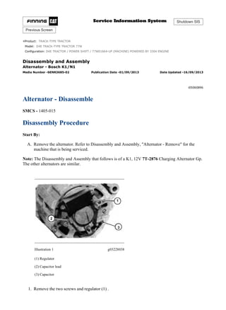
- 1. Shutdown SIS Previous Screen Product: TRACK-TYPE TRACTOR Model: D4E TRACK-TYPE TRACTOR 77W Configuration: D4E TRACTOR / POWER SHIFT / 77W01664-UP (MACHINE) POWERED BY 3304 ENGINE Disassembly and Assembly Alternator - Bosch K1/N1 Media Number -SENR3685-02 Publication Date -01/09/2013 Date Updated -16/09/2013 i05060896 Alternator - Disassemble SMCS - 1405-015 Disassembly Procedure Start By: A. Remove the alternator. Refer to Disassembly and Assembly, "Alternator - Remove" for the machine that is being serviced. Note: The Disassembly and Assembly that follows is of a K1, 12V 7T-2876 Charging Alternator Gp. The other alternators are similar. Illustration 1 g03228038 (1) Regulator (2) Capacitor lead (3) Capacitor 1. Remove the two screws and regulator (1) . 1/7 D4E TRACTOR / POWER SHIFT / 77W01664-UP (MACHINE) POWERED BY 33... 2019/8/27 https://127.0.0.1/sisweb/sisweb/techdoc/techdoc_print_page.jsp?returnurl=/sis...
- 2. 2. Disconnect capacitor lead (2) from the back of the alternator. Remove the screw and capacitor (3) . Illustration 2 g03228056 (4) Pulley (5) Fan 3. Remove the pulley nut, washer, pulley (4), fan (5), and the key from the rotor shaft. Illustration 3 g03228057 (6) Screws 4. Mark the front and rear frame assemblies for proper assembly. Remove four screws (6) (one has a nut on it on the back of the alternator). 5. Separate the front frame and rotor assembly from the rear frame and stator assembly. Watch for the wave washer, at the back of the rear frame assembly, to fall out. 2/7 D4E TRACTOR / POWER SHIFT / 77W01664-UP (MACHINE) POWERED BY 33... 2019/8/27 https://127.0.0.1/sisweb/sisweb/techdoc/techdoc_print_page.jsp?returnurl=/sis...
- 3. Illustration 4 g03228058 (7) Screws (8) Rotor 6. Remove four screws (7), and rotor (8) from the front frame. Illustration 5 g03228059 (9) Bearing cover (10) Spacer (11) Front bearing 7. Remove spacer (10), and front bearing (11), with a suitable puller. Remove bearing cover (9) from the rotor (8) . 3/7 D4E TRACTOR / POWER SHIFT / 77W01664-UP (MACHINE) POWERED BY 33... 2019/8/27 https://127.0.0.1/sisweb/sisweb/techdoc/techdoc_print_page.jsp?returnurl=/sis...
- 4. Illustration 6 g03228076 (12) Rear bearing (13) Slip ring 8. Remove the rear bearing (12) with a suitable puller. Unsolder both rotor winding leads from slip ring (13). Remove slip ring (13) with a suitable puller. Illustration 7 g03228080 (14) terminal nuts (15) terminal nuts (16) terminal nuts 9. Remove terminal nuts (14), (15), and (16). Remove all of the washers and insulators. 4/7 D4E TRACTOR / POWER SHIFT / 77W01664-UP (MACHINE) POWERED BY 33... 2019/8/27 https://127.0.0.1/sisweb/sisweb/techdoc/techdoc_print_page.jsp?returnurl=/sis...
- 5. Illustration 8 g03228097 (17) Screws 10. Remove three screws (17). Remove the stator and rectifier assembly from the rear frame. Remove the remaining insulators from the terminal studs. Illustration 9 g03228116 (18) Rectifier (19) Stator 11. Unsolder the three stator leads and separate rectifier (18) from stator (19) . 5/7 D4E TRACTOR / POWER SHIFT / 77W01664-UP (MACHINE) POWERED BY 33... 2019/8/27 https://127.0.0.1/sisweb/sisweb/techdoc/techdoc_print_page.jsp?returnurl=/sis...
- 6. Illustration 10 g03228119 K1 Alternator (1) Regulator (4) Pulley (5) Fan (6) Screws (8) Rotor (9) Bearing cover (11) Front bearing (12) Rear bearing (13) Slip ring (18) Rectifier (19) Stator 6/7 D4E TRACTOR / POWER SHIFT / 77W01664-UP (MACHINE) POWERED BY 33... 2019/8/27 https://127.0.0.1/sisweb/sisweb/techdoc/techdoc_print_page.jsp?returnurl=/sis...
- 7. Copyright 1993 - 2019 Caterpillar Inc. All Rights Reserved. Private Network For SIS Licensees. Tue Aug 27 17:27:28 UTC+0800 2019 7/7 D4E TRACTOR / POWER SHIFT / 77W01664-UP (MACHINE) POWERED BY 33... 2019/8/27 https://127.0.0.1/sisweb/sisweb/techdoc/techdoc_print_page.jsp?returnurl=/sis...
- 8. Shutdown SIS Previous Screen Product: TRACK-TYPE TRACTOR Model: D4E TRACK-TYPE TRACTOR 77W Configuration: D4E TRACTOR / POWER SHIFT / 77W01664-UP (MACHINE) POWERED BY 3304 ENGINE Disassembly and Assembly Alternator - Bosch K1/N1 Media Number -SENR3685-02 Publication Date -01/09/2013 Date Updated -16/09/2013 i05064230 Alternator - Assemble SMCS - 1405-016 Assembly Procedure Cleanliness is an important factor. Before assembly, all parts should be thoroughly cleaned in cleaning fluid. Allow the parts to air dry. Wiping cloths or rags should not be used to dry parts. Lint may be deposited on the parts which may cause problems in the future. Inspect all parts. If any parts are worn or damaged, use new parts for replacement. Illustration 1 g03230839 (1) Rectifier (2) Stator 1. Connect and solder the stator leads to the positive (+) diodes of rectifier (1) . 1/5 D4E TRACTOR / POWER SHIFT / 77W01664-UP (MACHINE) POWERED BY 33... 2019/8/27 https://127.0.0.1/sisweb/sisweb/techdoc/techdoc_print_page.jsp?returnurl=/sis...
- 9. Illustration 2 g03230840 (1) Rectifier (2) Stator (3) Position wave washer 2. Position the insulators on the rectifier terminal studs. Position rectifier (1), and stator (2) into the rear frame, and install the three screws. Install the terminal insulators, washers, and nuts. Position wave washer (3) into the bearing bore of the rear frame. Illustration 3 g03230842 (4) Rear bearing (5) Slip ring 3. Install slip ring (5) on the rotor. Connect and solder the rotor leads to the slip ring (5). Install rear bearing (4) . 2/5 D4E TRACTOR / POWER SHIFT / 77W01664-UP (MACHINE) POWERED BY 33... 2019/8/27 https://127.0.0.1/sisweb/sisweb/techdoc/techdoc_print_page.jsp?returnurl=/sis...
- 10. Illustration 4 g03230845 (6) Bearing cover (7) Spacer (8) Front bearing 4. Install bearing cover (6), front bearing (8), and spacer (7) on the rotor. Illustration 5 g03230846 (9) Rotor 5. Install rotor (9) and the four screws into the front frame. 3/5 D4E TRACTOR / POWER SHIFT / 77W01664-UP (MACHINE) POWERED BY 33... 2019/8/27 https://127.0.0.1/sisweb/sisweb/techdoc/techdoc_print_page.jsp?returnurl=/sis...
- 11. Illustration 6 g03230848 (10) Stator assembly (11) Rotor assembly 6. Assemble front frame and rotor assembly (11) into rear frame and stator assembly (10). Make sure that the wave washer is fixed in the rear frame bearing bore. Align the front and rear frame marks made at disassembly for correct assembly. Install the four screws. Illustration 7 g03230896 (12) Pulley (13) Fan 7. Install the key, fan (13), pulley (12), washer, and pulley nut. Tighten the nut to a torque of: 3E-7295 Charging Alternator Gp, and 9X-0341 Charging Alternator Gp ... 70 ± 5 N·m (52 ± 4 lb ft) 8C-5535 Charging Alternator Gp, 7T-2876 Charging Alternator Gp, 2Y-4212 Charging Alternator Gp, and 2Y-8310 Charging Alternator Gp ... 35 ± 10 N·m (26 ± 7 lb ft) 9W-3043 Charging Alternator Gp ... 50 ± 5 N·m (37 ± 4 lb ft) 4/5 D4E TRACTOR / POWER SHIFT / 77W01664-UP (MACHINE) POWERED BY 33... 2019/8/27 https://127.0.0.1/sisweb/sisweb/techdoc/techdoc_print_page.jsp?returnurl=/sis...
- 12. Illustration 8 g03230899 (14) Capacitor lead (15) Regulator 8. Install the capacitor and connect capacitor lead (14) to the back of the alternator. 9. Install regulator (15) . End By: Install the alternator on the machine. Refer to Disassembly and Assembly, "Alternator - Install" for the machine that is being serviced. Copyright 1993 - 2019 Caterpillar Inc. All Rights Reserved. Private Network For SIS Licensees. Tue Aug 27 17:28:18 UTC+0800 2019 5/5 D4E TRACTOR / POWER SHIFT / 77W01664-UP (MACHINE) POWERED BY 33... 2019/8/27 https://127.0.0.1/sisweb/sisweb/techdoc/techdoc_print_page.jsp?returnurl=/sis...
- 13. Shutdown SIS Previous Screen Product: TRACK-TYPE TRACTOR Model: D4E TRACK-TYPE TRACTOR 77W Configuration: D4E TRACTOR / POWER SHIFT / 77W01664-UP (MACHINE) POWERED BY 3304 ENGINE Disassembly and Assembly 3304B and 3306B Engines for Caterpillar Built Machines Media Number -SENR5598-09 Publication Date -01/01/2013 Date Updated -25/01/2013 i00984196 Fuel Priming Pump - Remove and Install SMCS - 1258-010 Removal Procedure NOTICE Keep all parts clean from contaminants. Contaminants may cause rapid wear and shortened component life. NOTICE Care must be taken to ensure that fluids are contained during performance of inspection, maintenance, testing, adjusting and repair of the machine. Be prepared to collect the fluid with suitable containers before opening any compartment or disassembling any component containing fluids. Refer to Special Publication, NENG2500, "Caterpillar Tools and Shop Products Guide", for tools and supplies suitable to collect and contain fluids in Caterpillar machines. Dispose of all fluids according to local regulations and mandates. 1/3 D4E TRACTOR / POWER SHIFT / 77W01664-UP (MACHINE) POWERED BY 33... 2019/8/27 https://127.0.0.1/sisweb/sisweb/techdoc/techdoc_print_page.jsp?returnurl=/sis...
- 14. Illustration 1 g00500957 1. Turn the fuel supply line valve to the OFF position. 2. Remove the bolts and the washers that secure fuel priming pump (1) to base (5). Remove gasket (4) . 3. Disconnect tube assembly (3) . 4. Remove two bolts (2), the washers and base (5) from the cylinder block. Installation Procedure NOTICE Keep all parts clean from contaminants. Contaminants may cause rapid wear and shortened component life. Illustration 2 g00500957 2/3 D4E TRACTOR / POWER SHIFT / 77W01664-UP (MACHINE) POWERED BY 33... 2019/8/27 https://127.0.0.1/sisweb/sisweb/techdoc/techdoc_print_page.jsp?returnurl=/sis...
- 15. 1. Install base (5), the washers and two bolts (2) . 2. Connect tube assembly (3) to base (5) . Note: Check the condition of the gaskets. If the gaskets are worn or damaged, use new parts for replacement. 3. Install gasket (4). Install fuel priming pump (1) and the bolts that secure the fuel priming pump to base (5) . 4. Turn the fuel supply line valve to the ON position. Copyright 1993 - 2019 Caterpillar Inc. All Rights Reserved. Private Network For SIS Licensees. Tue Aug 27 17:30:18 UTC+0800 2019 3/3 D4E TRACTOR / POWER SHIFT / 77W01664-UP (MACHINE) POWERED BY 33... 2019/8/27 https://127.0.0.1/sisweb/sisweb/techdoc/techdoc_print_page.jsp?returnurl=/sis...
- 16. Shutdown SIS Previous Screen Product: TRACK-TYPE TRACTOR Model: D4E TRACK-TYPE TRACTOR 77W Configuration: D4E TRACTOR / POWER SHIFT / 77W01664-UP (MACHINE) POWERED BY 3304 ENGINE Disassembly and Assembly 3304B and 3306B Engines for Caterpillar Built Machines Media Number -SENR5598-09 Publication Date -01/01/2013 Date Updated -25/01/2013 i00917143 Fuel Filter Base - Remove and Install SMCS - 1262-010 Removal Procedure Table 1 Required Tools Tool Part Number Part Description Qty A 2P-8250 Strap Wrench Assembly 1 NOTICE Keep all parts clean from contaminants. Contaminants may cause rapid wear and shortened component life. NOTICE Care must be taken to ensure that fluids are contained during performance of inspection, maintenance, testing, adjusting and repair of the machine. Be prepared to collect the fluid with suitable containers before opening any compartment or disassembling any component containing fluids. Refer to Special Publication, NENG2500, "Caterpillar Tools and Shop Products Guide", for tools and supplies suitable to collect and contain fluids in Caterpillar machines. 1/3 D4E TRACTOR / POWER SHIFT / 77W01664-UP (MACHINE) POWERED BY 33... 2019/8/27 https://127.0.0.1/sisweb/sisweb/techdoc/techdoc_print_page.jsp?returnurl=/sis...
- 17. Dispose of all fluids according to local regulations and mandates. Illustration 1 g00468389 1. Use Tool (A) to remove fuel filter (4) . 2. Disconnect fuel line (1) from fuel filter base (2) . 3. Remove two bolts (3), the washers, fuel filter base (2) and the gasket from the fuel injection pump housing. Installation Procedure Table 2 Required Tools Tool Part Number Part Description Qty A 2P-8250 Strap Wrench Assembly 1 NOTICE Keep all parts clean from contaminants. Contaminants may cause rapid wear and shortened component life. 2/3 D4E TRACTOR / POWER SHIFT / 77W01664-UP (MACHINE) POWERED BY 33... 2019/8/27 https://127.0.0.1/sisweb/sisweb/techdoc/techdoc_print_page.jsp?returnurl=/sis...
- 18. Illustration 2 g00468389 Note: Check the condition of the gaskets. If the gaskets are worn or damaged, use new parts for replacement. 1. Install the gasket, fuel filter base (2), the washers and two bolts (3) on the fuel injection pump housing. 2. Connect fuel line (1) to fuel filter base (2) . 3. Use Tool (A) to install fuel filter (4) . Copyright 1993 - 2019 Caterpillar Inc. All Rights Reserved. Private Network For SIS Licensees. Tue Aug 27 17:31:08 UTC+0800 2019 3/3 D4E TRACTOR / POWER SHIFT / 77W01664-UP (MACHINE) POWERED BY 33... 2019/8/27 https://127.0.0.1/sisweb/sisweb/techdoc/techdoc_print_page.jsp?returnurl=/sis...
- 19. Thank you very much for your reading. Please Click Here. Then Get COMPLETE MANUAL. NO WAITING NOTE: If there is no response to click on the link above, please download the PDF document first and then click on it.
- 20. Shutdown SIS Previous Screen Product: TRACK-TYPE TRACTOR Model: D4E TRACK-TYPE TRACTOR 77W Configuration: D4E TRACTOR / POWER SHIFT / 77W01664-UP (MACHINE) POWERED BY 3304 ENGINE Disassembly and Assembly 3304B and 3306B Engines for Caterpillar Built Machines Media Number -SENR5598-09 Publication Date -01/01/2013 Date Updated -25/01/2013 i00905874 Fuel Transfer Pump - Remove SMCS - 1256-011 Removal Procedure NOTICE Keep all parts clean from contaminants. Contaminants may cause rapid wear and shortened component life. NOTICE Care must be taken to ensure that fluids are contained during performance of inspection, maintenance, testing, adjusting and repair of the machine. Be prepared to collect the fluid with suitable containers before opening any compartment or disassembling any component containing fluids. Refer to Special Publication, NENG2500, "Caterpillar Tools and Shop Products Guide", for tools and supplies suitable to collect and contain fluids in Caterpillar machines. Dispose of all fluids according to local regulations and mandates. 1/2 D4E TRACTOR / POWER SHIFT / 77W01664-UP (MACHINE) POWERED BY 33... 2019/8/27 https://127.0.0.1/sisweb/sisweb/techdoc/techdoc_print_page.jsp?returnurl=/sis...
- 21. Illustration 1 g00462112 1. Turn the fuel supply line valve to the OFF position. 2. Remove tube assembly (2) and tube assembly (4) from fuel transfer pump (3) . 3. Remove bolts (1) and (5) from fuel transfer pump (3). Remove fuel transfer pump (3) and the O-ring seal. Copyright 1993 - 2019 Caterpillar Inc. All Rights Reserved. Private Network For SIS Licensees. Tue Aug 27 17:31:58 UTC+0800 2019 2/2 D4E TRACTOR / POWER SHIFT / 77W01664-UP (MACHINE) POWERED BY 33... 2019/8/27 https://127.0.0.1/sisweb/sisweb/techdoc/techdoc_print_page.jsp?returnurl=/sis...
- 22. Shutdown SIS Previous Screen Product: TRACK-TYPE TRACTOR Model: D4E TRACK-TYPE TRACTOR 77W Configuration: D4E TRACTOR / POWER SHIFT / 77W01664-UP (MACHINE) POWERED BY 3304 ENGINE Disassembly and Assembly 3304B and 3306B Engines for Caterpillar Built Machines Media Number -SENR5598-09 Publication Date -01/01/2013 Date Updated -25/01/2013 i01003268 Fuel Transfer Pump - Disassemble SMCS - 1256-015 Disassembly Procedure Start By: A. Remove the fuel transfer pump. Refer to Disassembly and Assembly, "Fuel Transfer Pump - Remove". NOTICE Keep all parts clean from contaminants. Contaminants may cause rapid wear and shortened component life. NOTICE Care must be taken to ensure that fluids are contained during performance of inspection, maintenance, testing, adjusting and repair of the machine. Be prepared to collect the fluid with suitable containers before opening any compartment or disassembling any component containing fluids. Refer to Special Publication, NENG2500, "Caterpillar Tools and Shop Products Guide", for tools and supplies suitable to collect and contain fluids in Caterpillar machines. Dispose of all fluids according to local regulations and mandates. 1/4 D4E TRACTOR / POWER SHIFT / 77W01664-UP (MACHINE) POWERED BY 33... 2019/8/27 https://127.0.0.1/sisweb/sisweb/techdoc/techdoc_print_page.jsp?returnurl=/sis...
- 23. Illustration 1 g00498289 Personal injury can result from parts and/or covers under spring pressure. Spring force will be released when covers are removed. Be prepared to hold spring loaded covers as the bolts are loosened. 1. Remove bolts (2) and cover (1) from the fuel transfer pump housing. Illustration 2 g00499040 2. Remove spring (4) from housing (3) . 2/4 D4E TRACTOR / POWER SHIFT / 77W01664-UP (MACHINE) POWERED BY 33... 2019/8/27 https://127.0.0.1/sisweb/sisweb/techdoc/techdoc_print_page.jsp?returnurl=/sis...
- 24. Illustration 3 g00498980 3. Remove O-ring seals (5) and (6) from cover (1) . 4. Remove valve assembly (7) from cover (1) . Illustration 4 g00498334 5. Remove piston (12) from sleeve (10). Remove washer (15), valve assembly (14) and seal (13) from piston (12) . 6. Remove sleeve (10) from housing (3). Remove O-ring seal (11) from sleeve (10) . 7. Remove guide and tappet assembly (9) and seal (8) from housing (3) . 3/4 D4E TRACTOR / POWER SHIFT / 77W01664-UP (MACHINE) POWERED BY 33... 2019/8/27 https://127.0.0.1/sisweb/sisweb/techdoc/techdoc_print_page.jsp?returnurl=/sis...