This document provides instructions for removing and installing an engine oil filter base on a C13 Industrial Engine N3F. The removal procedure involves draining the engine oil, then removing hoses, fittings, bolts and the oil filter base. Several internal components like springs and plungers must also be removed from the base. For installation, the base and components are reinstalled in reverse order, applying lubricant to seals and filters. Torque specifications are provided for tightening plugs and filters.
Core technology of Hyundai Motor Group's EV platform 'E-GMP'Hyundai Motor Group
What’s the force behind Hyundai Motor Group's EV performance and quality?
Maximized driving performance and quick charging time through high-density battery pack and fast charging technology and applicable to various vehicle types!
Discover more about Hyundai Motor Group’s EV platform ‘E-GMP’!
Comprehensive program for Agricultural Finance, the Automotive Sector, and Empowerment . We will define the full scope and provide a detailed two-week plan for identifying strategic partners in each area within Limpopo, including target areas.:
1. Agricultural : Supporting Primary and Secondary Agriculture
• Scope: Provide support solutions to enhance agricultural productivity and sustainability.
• Target Areas: Polokwane, Tzaneen, Thohoyandou, Makhado, and Giyani.
2. Automotive Sector: Partnerships with Mechanics and Panel Beater Shops
• Scope: Develop collaborations with automotive service providers to improve service quality and business operations.
• Target Areas: Polokwane, Lephalale, Mokopane, Phalaborwa, and Bela-Bela.
3. Empowerment : Focusing on Women Empowerment
• Scope: Provide business support support and training to women-owned businesses, promoting economic inclusion.
• Target Areas: Polokwane, Thohoyandou, Musina, Burgersfort, and Louis Trichardt.
We will also prioritize Industrial Economic Zone areas and their priorities.
Sign up on https://profilesmes.online/welcome/
To be eligible:
1. You must have a registered business and operate in Limpopo
2. Generate revenue
3. Sectors : Agriculture ( primary and secondary) and Automative
Women and Youth are encouraged to apply even if you don't fall in those sectors.
5 Warning Signs Your BMW's Intelligent Battery Sensor Needs AttentionBertini's German Motors
IBS monitors and manages your BMW’s battery performance. If it malfunctions, you will have to deal with an array of electrical issues in your vehicle. Recognize warning signs like dimming headlights, frequent battery replacements, and electrical malfunctions to address potential IBS issues promptly.
Ever been troubled by the blinking sign and didn’t know what to do?
Here’s a handy guide to dashboard symbols so that you’ll never be confused again!
Save them for later and save the trouble!
𝘼𝙣𝙩𝙞𝙦𝙪𝙚 𝙋𝙡𝙖𝙨𝙩𝙞𝙘 𝙏𝙧𝙖𝙙𝙚𝙧𝙨 𝙞𝙨 𝙫𝙚𝙧𝙮 𝙛𝙖𝙢𝙤𝙪𝙨 𝙛𝙤𝙧 𝙢𝙖𝙣𝙪𝙛𝙖𝙘𝙩𝙪𝙧𝙞𝙣𝙜 𝙩𝙝𝙚𝙞𝙧 𝙥𝙧𝙤𝙙𝙪𝙘𝙩𝙨. 𝙒𝙚 𝙝𝙖𝙫𝙚 𝙖𝙡𝙡 𝙩𝙝𝙚 𝙥𝙡𝙖𝙨𝙩𝙞𝙘 𝙜𝙧𝙖𝙣𝙪𝙡𝙚𝙨 𝙪𝙨𝙚𝙙 𝙞𝙣 𝙖𝙪𝙩𝙤𝙢𝙤𝙩𝙞𝙫𝙚 𝙖𝙣𝙙 𝙖𝙪𝙩𝙤 𝙥𝙖𝙧𝙩𝙨 𝙖𝙣𝙙 𝙖𝙡𝙡 𝙩𝙝𝙚 𝙛𝙖𝙢𝙤𝙪𝙨 𝙘𝙤𝙢𝙥𝙖𝙣𝙞𝙚𝙨 𝙗𝙪𝙮 𝙩𝙝𝙚 𝙜𝙧𝙖𝙣𝙪𝙡𝙚𝙨 𝙛𝙧𝙤𝙢 𝙪𝙨.
Over the 10 years, we have gained a strong foothold in the market due to our range's high quality, competitive prices, and time-lined delivery schedules.
Fleet management these days is next to impossible without connected vehicle solutions. Why? Well, fleet trackers and accompanying connected vehicle management solutions tend to offer quite a few hard-to-ignore benefits to fleet managers and businesses alike. Let’s check them out!
What Does the PARKTRONIC Inoperative, See Owner's Manual Message Mean for You...Autohaus Service and Sales
Learn what "PARKTRONIC Inoperative, See Owner's Manual" means for your Mercedes-Benz. This message indicates a malfunction in the parking assistance system, potentially due to sensor issues or electrical faults. Prompt attention is crucial to ensure safety and functionality. Follow steps outlined for diagnosis and repair in the owner's manual.
Things to remember while upgrading the brakes of your carjennifermiller8137
Upgrading the brakes of your car? Keep these things in mind before doing so. Additionally, start using an OBD 2 GPS tracker so that you never miss a vehicle maintenance appointment. On top of this, a car GPS tracker will also let you master good driving habits that will let you increase the operational life of your car’s brakes.
"Trans Failsafe Prog" on your BMW X5 indicates potential transmission issues requiring immediate action. This safety feature activates in response to abnormalities like low fluid levels, leaks, faulty sensors, electrical or mechanical failures, and overheating.
What Exactly Is The Common Rail Direct Injection System & How Does It WorkMotor Cars International
Learn about Common Rail Direct Injection (CRDi) - the revolutionary technology that has made diesel engines more efficient. Explore its workings, advantages like enhanced fuel efficiency and increased power output, along with drawbacks such as complexity and higher initial cost. Compare CRDi with traditional diesel engines and discover why it's the preferred choice for modern engines.
In this presentation, we have discussed a very important feature of BMW X5 cars… the Comfort Access. Things that can significantly limit its functionality. And things that you can try to restore the functionality of such a convenient feature of your vehicle.
Caterpillar Cat C13 Industrial Engine (Prefix N3F) Service Repair Manual Instant Download (N3F00001 and up).pdf
1. Product: INDUSTRIAL ENGINE
Model: C13 INDUSTRIAL ENGINE N3F
Configuration: C13 Industrial Engine N3F00001-UP
Disassembly and Assembly
C13 Industrial Engine
Media Number -UENR0184-02 Publication Date -01/06/2014 Date Updated -09/06/2014
i05351528
Air Inlet Elbow - Remove and Install
SMCS - 1087-010-E4
Removal Procedure
Table 1
Required Tools
Tool Part Number Part Description Qty
A -
LOCTITE
592 Thread Sealant
-
Start By:
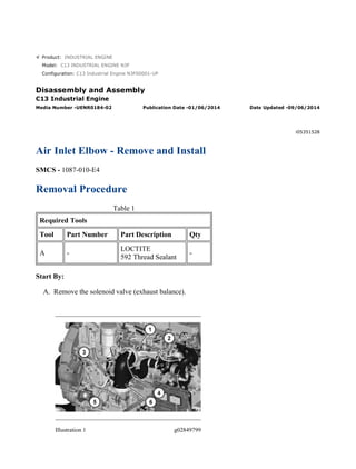
A. Remove the solenoid valve (exhaust balance).
Illustration 1 g02849799
1/4(W)
w
2022/3/19
https://127.0.0.1/sisweb/sisweb/techdoc/techdoc_print_page.jsp?returnurl=/sisweb/sisw...
2. 1. Disconnect the harness assembly from temperature sensor (5). Remove temperature sensor
(5) .
2. Remove hose assembly (4) and the fittings. Remove clip (3) .
3. Loosen the clamps for hose (2) and remove hose (2) .
4. Loosen clamp (1) and remove air inlet elbow (6) .
Illustration 2 g02849824
5. Disconnect the harness assembly from pressure sensor (7). Remove pressure sensor (7) .
6. Remove O-ring seal (8) and remove air inlet manifold (9). Remove and discard the gasket
from air inlet manifold (9) .
Illustration 3 g02849857
7. Remove bolts (11) and remove tube (10) and the O-ring seal.
2/4(W)
w
2022/3/19
https://127.0.0.1/sisweb/sisweb/techdoc/techdoc_print_page.jsp?returnurl=/sisweb/sisw...
3. Illustration 4 g02849867
8. Remove pin spring (12) and dowel (14) .
9. Remove tube (14) and the wave ring.
Illustration 5 g02849879
10. Remove plug (15) .
Installation Procedure
1. Install air inlet elbow (6) in the reverse order of removal.
a. Apply Tooling (A) to plug (15) .
3/4(W)
w
2022/3/19
https://127.0.0.1/sisweb/sisweb/techdoc/techdoc_print_page.jsp?returnurl=/sisweb/sisw...
4. Illustration 6 g02849917
b. Install pin spring (12) to the depth illustrated by Dimension (B). Dimension (B) is 6.0
± 0.50 mm (0.20 ± 0.020 inch).
c. Install dowel (14) to the depth illustrated by Dimension (C). Dimension (C) is 2.9 mm
(0.11 inch).
d. Tighten pressure sensor (7) to a torque of 10 ± 2 N·m (89 ± 18 lb in).
e. Tighten temperature sensor (5) to a torque of 20 ± 3 N·m (177 ± 27 lb in).
f. Tighten clamp (1) to a torque of 8.5 ± 2 N·m (75 ± 18 lb in).
4/4(W)
w
2022/3/19
https://127.0.0.1/sisweb/sisweb/techdoc/techdoc_print_page.jsp?returnurl=/sisweb/sisw...
5. Product: INDUSTRIAL ENGINE
Model: C13 INDUSTRIAL ENGINE N3F
Configuration: C13 Industrial Engine N3F00001-UP
Disassembly and Assembly
C13 Industrial Engine
Media Number -UENR0184-02 Publication Date -01/06/2014 Date Updated -09/06/2014
i03537718
Inlet and Exhaust Valve Springs - Remove and Install
SMCS - 1108-010
Removal Procedure
Table 1
Required Tools
Tool Part Number Part Description Qty
A 235-0518 Valve Spring Compression Group 1
Start By:
a. Remove the electronic unit injectors.
Note: The following procedure is for the removal of the inlet valve springs and the exhaust valve
springs without removing the cylinder head. This procedure can be performed on only one
cylinder at a time. This will prevent the inlet valves and the exhaust valves from falling into the
cylinder.
1. Rotate the crankshaft in order to bring the piston to the top center position in the cylinder.
1/3(W)
w
2022/3/19
https://127.0.0.1/sisweb/sisweb/techdoc/techdoc_print_page.jsp?returnurl=/sisweb/sisw...
6. Illustration 1 g01136330
Personal injury can result from being struck by parts propelled by a
released spring force.
Make sure to wear all necessary protective equipment.
Follow the recommended procedure and use all recommended tooling to
release the spring force.
2. Install Tooling (A) on the cylinder head.
3. Remove retainer locks (1).
2/3(W)
w
2022/3/19
https://127.0.0.1/sisweb/sisweb/techdoc/techdoc_print_page.jsp?returnurl=/sisweb/sisw...
7. 4. Remove Tooling (A).
5. Remove valve rotators (2).
6. Remove valve springs (3) and valve springs (4) from each valve.
7. Remove bases (5) from the cylinder head.
Note: Install the valve springs before you rotate the crankshaft.
Installation Procedure
The valve keepers can be thrown from the valve when the valve spring
compressor is released. Ensure that the valve keepers are properly
installed on the valve stem. To help prevent personal injury, keep away
from the front of the valve keepers and valve springs during the
installation of the valves.
Note: A small amount of grease can be used to hold the retainer locks in position during
installation.
Note: Lubricate the valve stems with clean engine oil.
1. Install valve springs (3) and (4) in reverse order of removal.
3/3(W)
w
2022/3/19
https://127.0.0.1/sisweb/sisweb/techdoc/techdoc_print_page.jsp?returnurl=/sisweb/sisw...
8. Product: INDUSTRIAL ENGINE
Model: C13 INDUSTRIAL ENGINE N3F
Configuration: C13 Industrial Engine N3F00001-UP
Disassembly and Assembly
C13 Industrial Engine
Media Number -UENR0184-02 Publication Date -01/06/2014 Date Updated -09/06/2014
i03538279
Inlet and Exhaust Valves - Remove and Install
SMCS - 1105-010
Removal Procedure
Table 1
Required Tools
Tool Part Number Part Description Qty
A 5S-1330 Valve Spring Compressor 1
Start By:
a. Remove the cylinder head.
1/3(W)
w
2022/3/19
https://127.0.0.1/sisweb/sisweb/techdoc/techdoc_print_page.jsp?returnurl=/sisweb/sisw...
9. Illustration 1 g01131781
Personal injury can result from being struck by parts propelled by a
released spring force.
Make sure to wear all necessary protective equipment.
Follow the recommended procedure and use all recommended tooling to
release the spring force.
1. Use Tooling (A) to remove retainer locks (1).
2. Remove valve rotators (2).
2/3(W)
w
2022/3/19
https://127.0.0.1/sisweb/sisweb/techdoc/techdoc_print_page.jsp?returnurl=/sisweb/sisw...
10. 3. Remove valve springs (3) and valve springs (4).
4. Remove base (5).
5. Remove valves (6) from the cylinder head.
6. Remove valve seals (7).
Installation Procedure
The valve keepers can be thrown from the valve when the valve spring
compressor is released. Ensure that the valve keepers are properly
installed on the valve stem. To help prevent personal injury, keep away
from the front of the valve keepers and valve springs during the
installation of the valves.
Note: A small amount of grease can be used to hold the retainer locks in position during
installation.
Note: Lubricate valves (6) with clean engine oil.
1. Install valves (6) in reverse order of removal.
3/3(W)
w
2022/3/19
https://127.0.0.1/sisweb/sisweb/techdoc/techdoc_print_page.jsp?returnurl=/sisweb/sisw...
11. Product: INDUSTRIAL ENGINE
Model: C13 INDUSTRIAL ENGINE N3F
Configuration: C13 Industrial Engine N3F00001-UP
Disassembly and Assembly
C13 Industrial Engine
Media Number -UENR0184-02 Publication Date -01/06/2014 Date Updated -09/06/2014
i05888682
Inlet and Exhaust Valve Guides - Remove and Install
SMCS - 1104-010
Removal Procedure
Table 1
Required Tools
Tool Part Number Part Description Qty
A 1U-9169 Valve Guide Driver 1
B
124-9057 Guide Collar 1
9U-6895 Valve Guide Driver 1
C(1)
455-0128 Seal Installer 1
375-2773 Seal Installer 1
(1)
Use Seal Installer 455-0128 with Seal 163-2478. Use Seal Installer 375-2773 with Seal 361-3926.
Start By:
a. Remove the inlet valves and exhaust valves.
1/3(W)
w
2022/3/19
https://127.0.0.1/sisweb/sisweb/techdoc/techdoc_print_page.jsp?returnurl=/sisweb/sisw...
12. Illustration 1 g03711984
1. Remove seals (1) from valve guides (2).
Illustration 2 g03711987
2. Use Tooling (A) to remove the valve guides (2) from the cylinder head assembly.
Installation Procedure
Note: Lubricate the bores for the valve guides with clean engine oil.
1. Use Tooling (B) to install valve guides (2) in reverse order of removal.
2/3(W)
w
2022/3/19
https://127.0.0.1/sisweb/sisweb/techdoc/techdoc_print_page.jsp?returnurl=/sisweb/sisw...
13. Illustration 3 g01301738
a. Install valve guides (1) until the protrusion is Dimension (X) above the cylinder head
assembly. Dimension (X) is 20.0 ± 0.5 mm (0.79 ± 0.02 inch).
b. Use Tooling (C) to install seals (1).
3/3(W)
w
2022/3/19
https://127.0.0.1/sisweb/sisweb/techdoc/techdoc_print_page.jsp?returnurl=/sisweb/sisw...
14. Product: INDUSTRIAL ENGINE
Model: C13 INDUSTRIAL ENGINE N3F
Configuration: C13 Industrial Engine N3F00001-UP
Disassembly and Assembly
C13 Industrial Engine
Media Number -UENR0184-02 Publication Date -01/06/2014 Date Updated -09/06/2014
i03538303
Inlet and Exhaust Valve Seat Inserts - Remove and Install
SMCS - 1103-010
Removal Procedure
Table 1
Required Tools
Tool Part Number Part Description Qty
A 166-7441 Valve Seat Extractor Tool 1
B 1U-9170 Valve Seat Driver 1
Start By:
a. Remove the inlet and exhaust valves.
1/3(W)
w
2022/3/19
https://127.0.0.1/sisweb/sisweb/techdoc/techdoc_print_page.jsp?returnurl=/sisweb/sisw...
15. Illustration 1 g01082582
1. Use Tooling (A) to remove valve seat inserts (1).
Installation Procedure
Illustration 2 g01079028
Note: Do not machine the prefinished valve seat inserts in order to correct the valve stem
projection. An excessive valve stem projection indicates that the valve seat insert is not
seated or material was not cleaned from the bottom of the counterbore.
1. Lower the temperature of new valve seat inserts (1).
2. Use Tooling (B) to install the new valve seat inserts (1) in reverse order of removal.
2/3(W)
w
2022/3/19
https://127.0.0.1/sisweb/sisweb/techdoc/techdoc_print_page.jsp?returnurl=/sisweb/sisw...
16. Product: INDUSTRIAL ENGINE
Model: C13 INDUSTRIAL ENGINE N3F
Configuration: C13 Industrial Engine N3F00001-UP
Disassembly and Assembly
C13 Industrial Engine
Media Number -UENR0184-02 Publication Date -01/06/2014 Date Updated -09/06/2014
i05351529
Engine Oil Filter Base - Remove and Install
SMCS - 1306-010
Removal Procedure
Table 1
Required Tools
Tool Part Number Part Description Qty
A 185-3630 Strap Wrench As 1
Illustration 1 g02174574
1. Refer to Operation and Maintenance Manual, "Engine Oil and Filter - Change" for the
proper draining and filling procedures.
2. Disconnect tube assembly (3). Remove bolts (1 ) and elbow (2) .
1/5(W)
w
2022/3/19
https://127.0.0.1/sisweb/sisweb/techdoc/techdoc_print_page.jsp?returnurl=/sisweb/sisw...
17. Illustration 2 g02174551
3. Remove bolts (4) and bolts (5). Remove manifold (6) and coupling (7) .
Illustration 3 g01859093
4. Disconnect hose assembly (8). Remove hose assemblies (9). Remove bolts (10) and bolts
(11). Remove oil filter base (12) and the O-ring seals.
Illustration 4 g02850764
2/5(W)
w
2022/3/19
https://127.0.0.1/sisweb/sisweb/techdoc/techdoc_print_page.jsp?returnurl=/sisweb/sisw...
18. Personal injury can result from being struck by parts propelled by a
released spring force.
Make sure to wear all necessary protective equipment.
Follow the recommended procedure and use all recommended tooling to
release the spring force.
5. Remove plug (15), spring (14), and plunger (13) from oil filter base (12) .
Illustration 5 g02850770
Personal injury can result from being struck by parts propelled by a
released spring force.
Make sure to wear all necessary protective equipment.
Follow the recommended procedure and use all recommended tooling to
release the spring force.
6. Remove plug (18), spring assembly (17), and valve (16) from oil filter base (12) .
3/5(W)
w
2022/3/19
https://127.0.0.1/sisweb/sisweb/techdoc/techdoc_print_page.jsp?returnurl=/sisweb/sisw...
19. Illustration 6 g02850774
Personal injury can result from being struck by parts propelled by a
released spring force.
Make sure to wear all necessary protective equipment.
Follow the recommended procedure and use all recommended tooling to
release the spring force.
7. Remove bolt (23), seat (22), spring (21), retainer (20), and spacer (19) from oil filter base
(12) .
Illustration 7 g02850818
8. Use Tooling (A) to remove oil filter (26) from remote engine oil filter base (25). Remove
bolts (24) and remote engine oil filter base (25) .
4/5(W)
w
2022/3/19
https://127.0.0.1/sisweb/sisweb/techdoc/techdoc_print_page.jsp?returnurl=/sisweb/sisw...
20. Illustration 8 g02850820
Personal injury can result from being struck by parts propelled by a
released spring force.
Make sure to wear all necessary protective equipment.
Follow the recommended procedure and use all recommended tooling to
release the spring force.
9. Remove plug (29), spring (28), and plunger (27) from remote engine oil filter base (25) .
Installation Procedure
1. Install remote engine oil filter base (25) and oil filter base (12) in the reverse order of
removal.
a. Apply lubricant that is being sealed to all O-ring seals and the filters.
b. Tighten plug (29) to a torque of 100 ± 15 N·m (74 ± 11 lb ft).
c. Use Tooling (A) to tighten oil filter (26) to a torque of 65 ± 3 N·m (48 ± 2 lb ft).
d. Tighten plug (18) to a torque of 100 ± 15 N·m (74 ± 11 lb ft).
e. Tighten plug (15) to a torque of 100 ± 15 N·m (74 ± 11 lb ft).
5/5(W)
w
2022/3/19
https://127.0.0.1/sisweb/sisweb/techdoc/techdoc_print_page.jsp?returnurl=/sisweb/sisw...
21. Product: INDUSTRIAL ENGINE
Model: C13 INDUSTRIAL ENGINE N3F
Configuration: C13 Industrial Engine N3F00001-UP
Disassembly and Assembly
C13 Industrial Engine
Media Number -UENR0184-02 Publication Date -01/06/2014 Date Updated -09/06/2014
i03529781
Engine Oil Cooler - Remove and Install
SMCS - 1378-010
Removal Procedure
Start By:
a. Remove the turbocharger
1. Refer to Operation and Maintenance Manual, "Cooling System Coolant (ELC) - Change"
for the correct draining and filling procedures.
Illustration 1 g02175060
2. Remove tube assemblies (1) and (2).
3. Remove clamps (3) and the hose.
4. Remove tube assembly (4).
5. Disconnect hose assembly (5).
1/2(W)
w
2022/3/19
https://127.0.0.1/sisweb/sisweb/techdoc/techdoc_print_page.jsp?returnurl=/sisweb/sisw...
22. Suggest:
For more complete manuals. Please go to
the home page.
https://www.ebooklibonline.com
If the above button click is invalid. Please
download this document first, and then
click the above link to download the
complete manual.
Thank you so much for reading
23. Illustration 2 g01858607
6. Remove bolts (6). Remove engine oil cooler (7).
Installation Procedure
1. Install engine oil cooler (7) in reverse order of removal.
a. Tighten hose clamps (3) to a torque of 14 ± 1 N·m (124 ± 9 lb in).
2/2(W)
w
2022/3/19
https://127.0.0.1/sisweb/sisweb/techdoc/techdoc_print_page.jsp?returnurl=/sisweb/sisw...
24. Product: INDUSTRIAL ENGINE
Model: C13 INDUSTRIAL ENGINE N3F
Configuration: C13 Industrial Engine N3F00001-UP
Disassembly and Assembly
C13 Industrial Engine
Media Number -UENR0184-02 Publication Date -01/06/2014 Date Updated -09/06/2014
i06302536
Engine Oil Pump - Remove and Install
SMCS - 1304-010
Removal Procedure
1. Drain the coolant from the cooling system into a suitable container for storage or for
disposal. Refer to Operation and Maintenance Manual, "Cooling System Coolant (ELC) -
Change".
Illustration 1 g02174574
2. Remove bolts (1) and elbow (2) .
3. Disconnect hose assembly (3) .
1/2(W)
w
2022/3/19
https://127.0.0.1/sisweb/sisweb/techdoc/techdoc_print_page.jsp?returnurl=/sisweb/sisw...