Downloaded 32 times


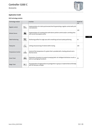
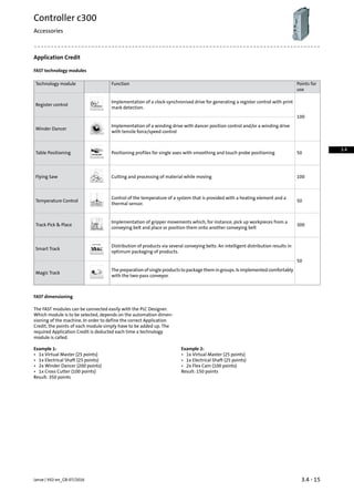
![Functions and features
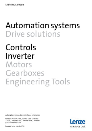
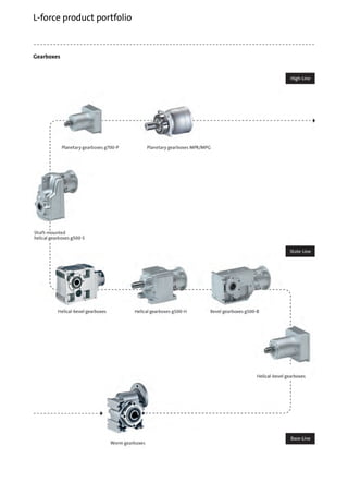
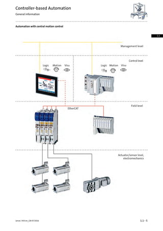
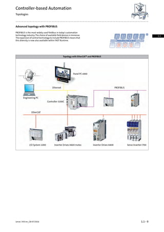
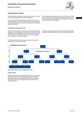
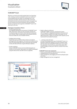
Servo-Inverter i700
The Servo-Inverter i700 is implemented into the Controller-based
Automation solution via the Ethernet-based EtherCAT® bus system.
Thus, a large variety of technology applications can be adopted via
the implemented controller.
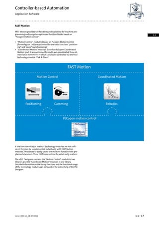
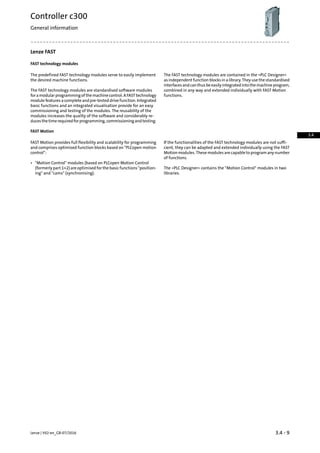
The »PLC Designer« engineering tool serves to program the FAST
Motion functions.
Controller p500 with Servo-Inverter i700Controller 3200 C with Servo-Inverter i700
For the different controllers, cycle times of the setpoint selection de-
pend on the number of axes and the functionalities. The following
table shows typical values for "Motion Control" (based on PLCopen
Motion Control, formerly Part 1+2) and "Coordinated Motion" (based
on PLCopen Coordinated Motion, Part 4).
Mode
p5003251 C3231 C3221 CController
Min. cycle time PLCopen part
1,2: Motion Control
1[ms]t2 axes
1[ms]t4 axes
1[ms]t8 axes
12[ms]t12 axes
2[ms]t16 axes
3[ms]t32 axes
56[ms]t64 axes
Min. cycle time PLCopen part 4:
Coordinated Motion
12[ms]t2 axes
12[ms]t4 axes
23[ms]t8 axes
Lenze | V03-en_GB-07/20161.1 - 18
Controller-based Automation
Application areas
1.1](https://image.slidesharecdn.com/catalogue-lenzefastmotioncontrolsolutionsportfolio-160730160451/85/Catalogue-Lenze-FAST-motion-control-solutions-portfolio-28-320.jpg)

![9Lenze | V01-en_EN-11/2015
3.1
3.3
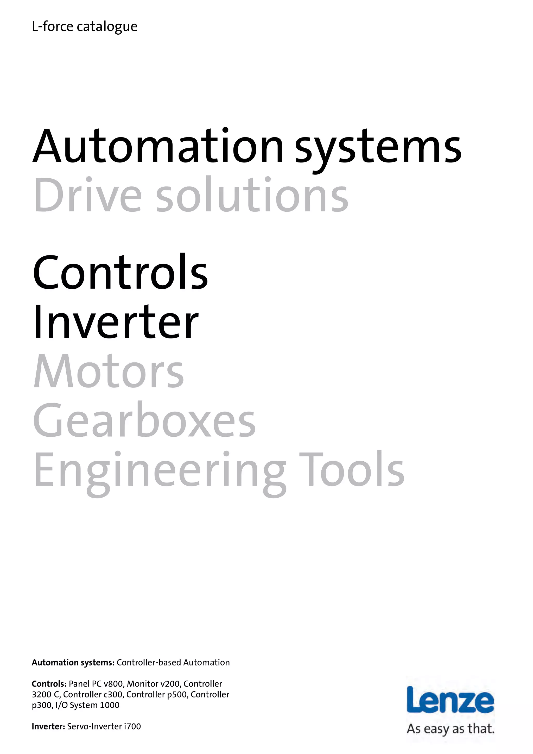
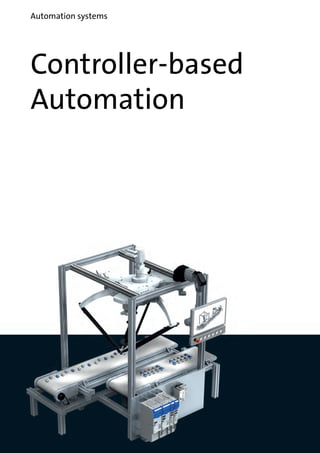
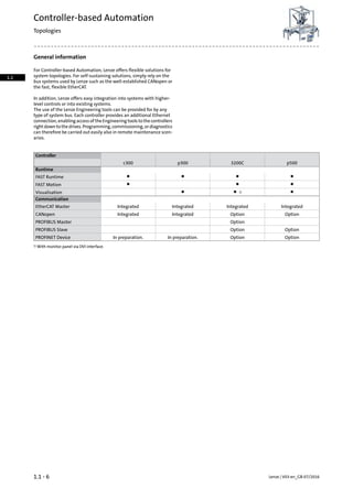
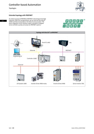
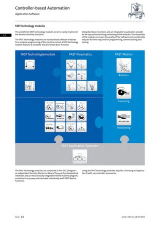
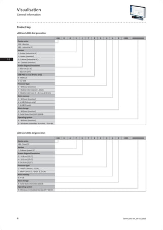
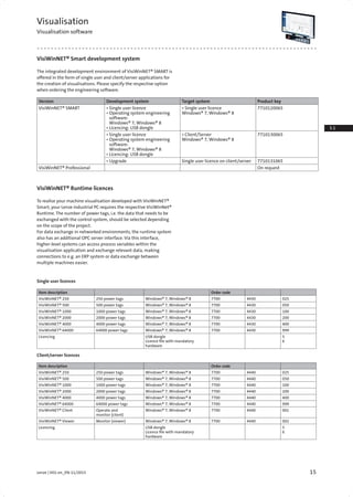
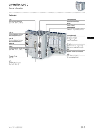
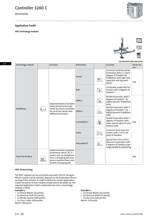
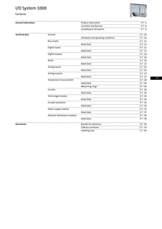
Rated data v800 and v200-Protec
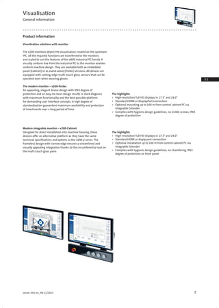
Visualisation
Technical data
Version v800-P v200-P
Screen diagonal 43.9 cm
(17.3")
61 cm
(24")
43.9 cm
(17.3")
61 cm
(24")
43.9 cm
(17.3")
61 cm
(24")
Resolution Pixel 1920 x 1080 1920 x 1080 1920 x 1080
Touch Capacitive
glass surface,
Multi-Touch
Capacitive
glass surface,
Multi-Touch
Capacitive
glass surface,
Multi-Touch
Processor type Intel® Celeron®
Processor 2980U
(2M Cache, 1.60 GHz)
Intel® Core™ i5-4300U
Processor (3M Cache,
1.90 up to 2.90 GHz)
Graphics processor Intel® HD Graphics Intel® HD Graphics 4400
Operating system Windows Embedded
Standard 7 P 64 Bit
Windows Embedded
Standard 7 P 64 Bit
Storage medium
Mass storage [GB] 120 (2.5" SSD) 120 (2.5" SSD)
Internal memory [GB] 4 8
Interfaces
USB host 3.0/2.0
1x external access point
2 / 1 2 / 1 - /2
USB Device 2.0 2 2 1
Ethernet
(10/100/1000 Mbit/s)
2 2
HDMI / display port 1/1
Rated voltage DC UN, DC [V] 24 (+/- 20%) 24 (+/- 20%) 24 (+/- 20%)
Max. current consumption
(incl. USB)
I [A] 3 4 3 4 2 2
Maximum starting current l [A] 4 4 4 4 3 3
Fusing of supply
voltage
l [A] 4
slow-blow
6
slow-blow
4
slow-blow
6
slow-blow
4
slow-blow
4
slow-blow
Weight m [kg] 4.8 7.7 4.8 7.7 4.6 7.5
Dimensions incl. switch box Wx-
HxD
[mm] 431x351x
216
578x436x
216
431x351x
216
578x436x
216
431x351x
216
578x436x
216
Dimensions without switch box Wx-
HxD
[mm] 431x261x
216
578x347x
216
431x261x
216
578x347x
216
431x261x
216
578x347x
216](https://image.slidesharecdn.com/catalogue-lenzefastmotioncontrolsolutionsportfolio-160730160451/85/Catalogue-Lenze-FAST-motion-control-solutions-portfolio-39-320.jpg)
![10 Lenze | V01-en_EN-11/2015
1.1
1.2
1.2
2.2
2.3
3.1
3.2
3.4
4.2
4.3
4.4
4.5
4.
4.
4.9
4.10
4.11
4.12
5.1
5.2
5.
5.4
5.
5.6
5.7
5.8
5.
5.10
6.1
6.2
6.3
6.
6.5
6.6
6.7
7.1
7.2
7.3
7.4
7.5
7.6
7.
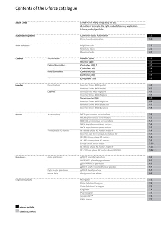
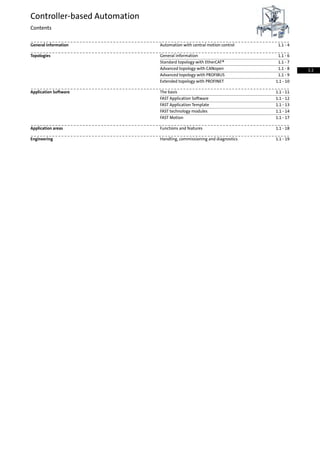
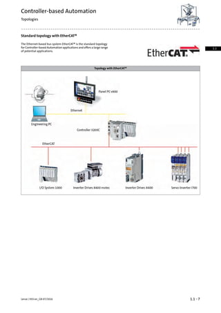
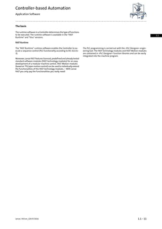
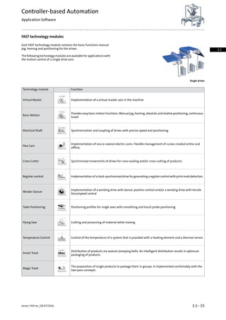
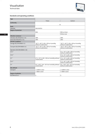
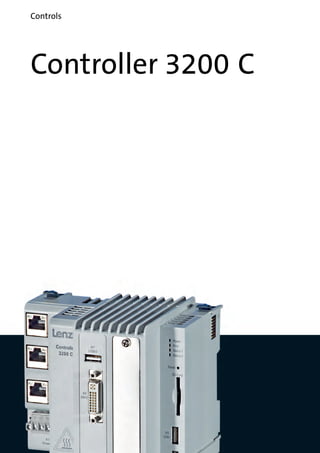
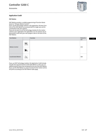
Visualisation
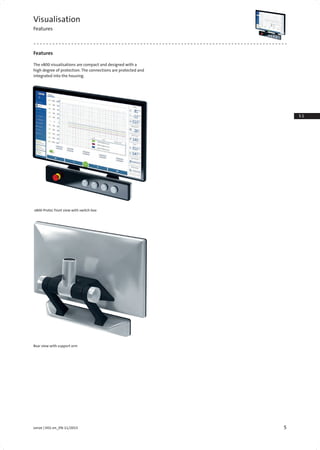
Technical data
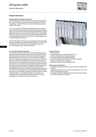
Rated data v800 and v200-Cabinet, 2nd generation
Version v800-C v200-C
Screen diagonal 43.9 cm
(17.3")
61 cm
(24")
43.9 cm
(17.3")
61 cm
(24")
43.9 cm
(17.3")
61 cm
(24")
Resolution Pixel 1920 x 1080 1920 x 1080 1920 x 1080
Touch capacitive
glass surface,
Multi-Touch
capacitive
glass surface,
Multi-Touch
capacitive
glass surface,
Multi-Touch
Processor type Intel® Celeron®
Processor 2980U
(2M Cache, 1.60 GHz)
Intel® Core™ i5-4300U
Processor (3M Cache,
1.90 up to 2.90 GHz)
Graphics processor Intel® HD Graphics Intel® HD Graphics 4400
Operating system Windows Embedded
Standard 7 P 64 Bit
Windows Embedded
Standard 7 P 64 Bit
Storage medium
Mass storage [GB] 120 (2.5" SSD) 120 (2.5" SSD)
Internal memory [GB] 4 8
Interfaces
USB host 3.0/2.0
1x external access point
2 / 1 2 / 1 - /2
USB Device 2.0 2 2 1
Ethernet
(10/100/1000 Mbit/s)
2 2
HDMI / DisplayPort 1/1
Rated voltage DC UN, DC [V] 24 (+/- 20%) 24 (+/- 20%) 24 (+/- 20%)
Max. current consumption
(incl. USB)
l [A] 3 4 3 4 2 2
Maximum starting current I [A] 4 4 4 4 3 3
Fusing of supply
voltage
l [A] 4
slow-blow
6
slow-blow
4
slow-blow
6
slow-blow
4
slow-blow
4
slow-blow
Dimension Wx-
HxD
[mm] 433x263x
89
580x349x
89
433x263x
89
580x349x
89
433x263x
89
580x349x
89
Mounting depth D [mm] 79 79 79 79 62 62
Mounting cutout WxH [mm] 422x252 569x338 422x252 569x338 422x252 569x338](https://image.slidesharecdn.com/catalogue-lenzefastmotioncontrolsolutionsportfolio-160730160451/85/Catalogue-Lenze-FAST-motion-control-solutions-portfolio-40-320.jpg)
![11Lenze | V01-en_EN-11/2015
3.1
3.3
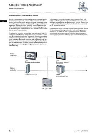
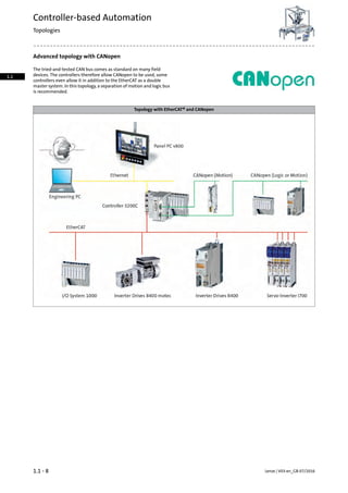
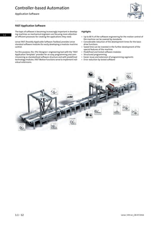
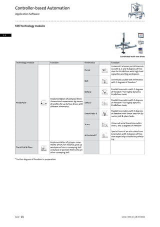
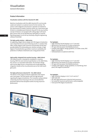
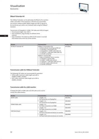
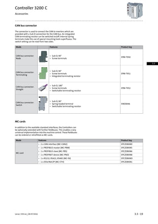
Visualisation
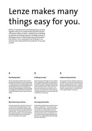
Technical data
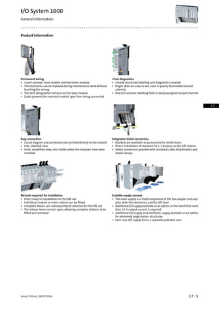
Rated data v800-Cabinet, 1st generation
Version v800-C
Screen diagonal 33.8 cm
(13.3")
39.1 cm
(15.4")
54.6 cm
(21.5")
33.8 cm
(13.3")
39.1 cm
(15.4")
54.6 cm
(21.5")
Resolution 1280 x
800
1280 x
800
1920 x
1080
1280 x
800
1280 x
800
1920 x
1080
Touch capacitive
glass surface,
Multi-Touch
capacitive
glass surface,
Multi-Touch
Processor type Intel® Celeron®
Processor 2002E
(2M Cache, 1.50 GHz)
Intel® Core™ i5-4400E
Processor (3M Cache,
2.70 up to 3.30 GHz)
Graphics processor Intel® HD Graphics Intel® HD Graphics 4600
Operating system Windows® Embedded
Standard 7 P 64 bit
Windows® Embedded
Standard 7 P 64 bit
Storage medium
Mass storage [GB] 120 (2.5" SSD) 120 (2.5" SSD)
Internal memory [GB] 4 8
Interfaces
COM (RS232) 1 1
USB Device 2.0 2/2 on rear 2/2 on rear
Ethernet
(10/100/1000 Mbit/s)
3 3
Rated voltage DC UN, DC [V] 24 (+/- 20%) 24 (+/- 20%) 24 (+/- 20%)
Max. current consumption
(incl. USB)
l [A] 3 4 3 4 3 4
Maximum starting current l [A] 8 8 8 8 8 8
Fusing of supply
voltage
l [A] 4
slow-blow
4
slow-blow
4
slow-blow
4
slow-blow
6
slow-blow
6
slow-blow
Weight m [kg] 3.6 4.9 8.6 3.6 4.9 8.6
Dimension Wx-
HxD
[mm] 353 x
261 x
63
426 x
261 x
66
567 x
369 x
66
353 x
261 x
63
426 x
261 x
66
567 x
369 x
66
Mounting depth D [mm] 51 54 54 51 54 54
Mounting cutout WxH [mm] 332 x 240 392 x 269 532 x 334 332x240 392 x 269 532 x 334](https://image.slidesharecdn.com/catalogue-lenzefastmotioncontrolsolutionsportfolio-160730160451/85/Catalogue-Lenze-FAST-motion-control-solutions-portfolio-41-320.jpg)
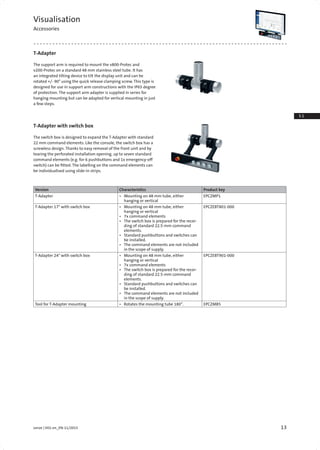


![Standards and operating conditions
Mode
3251 C3231 C3221 CController
Conformity
Low-Voltage DirectiveCE
2014/30/EU
TP TC 020/2011 (TR CU 020/2011)EAC
Approval
Process Control Equipment (File-No. E236341)UL 508C
CSA 22.2 No.142UL/CSA
Degree of protection
IP20EN 60529
Type 1NEMA 250
Climatic conditions
1K3 (Temperature: -5 °C ... +45 °C)Storage (EN 60721-3-1)
2K3 (temperature: -25 °C ... +70 °C)Transport (EN 60721-3-2)
3K3 (temperature: 0 °C ... +50 °C)1)3K3 (temperature: 0 °C ...
+55 °C)1)
Operation (EN 60721-3-3)
3K3 (temperature: 0 °C ... +45 °C)2)
3K3 (temperature: 0 °C ...
+50 °C)2)
Degree of pollution
2EN 61131-2
Site altitude
3000[m]HmaxAmsl
Vibration resistance
1 gVibration (EN 61131-2)
15 gMechanical shock (EN 61131-2)
5 Hz ≤ f ≤ 13.2 Hz: ± 1 mm amplitudeOperation (Germanischer Lloyd)
13.2 Hz ≤ f ≤ 100 Hz: 0.7 g
Noise emission
Industrial premisesEN 61000-6-4
Noise immunity
ESD: Severity 3EN 61000-4-2
150 kHz ... 80 MHz, 10 V/m 80 % AM (1 kHz)EN 61000-4-6
80 kHz ... 1000 MHz, 10 V/m 80 % AM (1 kHz)EN 61000-4-3
1.4 GHz ... 2.0 GHz, 3 V/m, 80 % AM (1kHz)
2.0 GHz ... 2.7 GHz, 1 V/m, 80 % AM (1kHz)
Burst: Severity 3EN 61000-4-4
Horizontal mounting1)
Vertical mounting2)
Lenze | V03-en_GB-07/20163.3 - 10
Controller 3200 C
Technical data
3.3](https://image.slidesharecdn.com/catalogue-lenzefastmotioncontrolsolutionsportfolio-160730160451/85/Catalogue-Lenze-FAST-motion-control-solutions-portfolio-56-320.jpg)
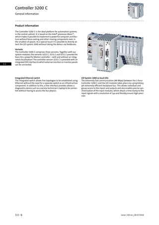
![Rated data
Mode
3251 C3231 C3221 CController
Processor type
Intel® Atom™ 1.91 GHzIntel® Atom™ 1.75 GHzIntel® Atom™ 1.46 GHzFanless
Storage medium
512[MB]SD card1)
Interfaces
2Ethernet (integrated switch)
1EtherCAT Master
32USB
1DVI-D
1ACU (external energy storage)
Interface connection for PROFINET-Device (MC-PND)Option
Interface connection for CANopen (MC-CAN2)
Interface connection for PROFIBUS Master (MC-PBM)
Interface connection for PROFIBUS Slave (MC-PBS)
Interface connection for RS232, 422, 485 (MC-ISI)
-
Rated voltage
24[V]UN, DCDC
Max. current consumption
1.201.00[A]ImaxWith connected I/Os
0.800.60[A]ImaxWithout connected I/Os
Operating system
Windows® CE 6.0
Memory size
512[MB]Program memory
512[MB]Data memory
4[kB]Flags
102460[kB]Retain data
100000Max. number of persistently saved
visualisation alarms
2[GB]Main memory (RAM)
4[GB]Min. internal flash memory
Runtime
●FAST Runtime
●Visualisation2)
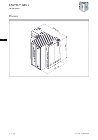
Dimensions
112 x 136 x 105[mm]h x b x t
Mass
0.70[kg]m
1 x SD card included in the scope of supply.1)
Controller 3231 C with external monitor at the DVI-D interface. For operation,
power tags are required.
2)
3.3 - 11Lenze | V03-en_GB-07/2016
Controller 3200 C
Technical data
3.3](https://image.slidesharecdn.com/catalogue-lenzefastmotioncontrolsolutionsportfolio-160730160451/85/Catalogue-Lenze-FAST-motion-control-solutions-portfolio-57-320.jpg)
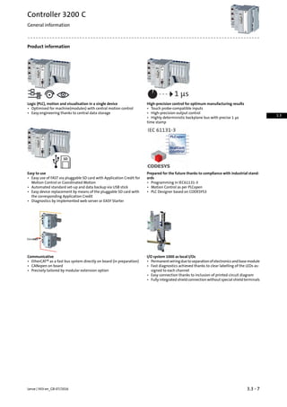
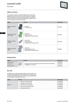
![SD card and USB flash drive
SD cards and USB flash drives are available for data storage and data
backups.
ƒ A SD card is part of the scope of supply of the controller.
ƒ SD card without Application Credit.
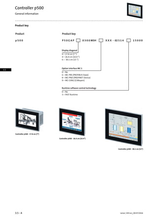
Product keyFeaturesMode
Application Credit 0 • 512 MB
EPCZEMUS4
USB flash drive
• 1 GB
EPCZEMUS6• 4 GB
24 V power supply unit
An external power supply unit is also available as an alternative for
powering the controller's control electronics.
24 V power supply unit
Rated data
Product key
EZV2400-000
Rated voltage
230[V]UN, ACAC
Rated mains current
1.20[A]IN, AC
Output voltage
DC 22.5 ...28.5[V]Uout
Rated current
10.0[A]IN
Dimensions
130 x 85 x 125[mm]h x b x t
Mass
1.24[kg]m
Lenze | V03-en_GB-07/20163.3 - 18
Controller 3200 C
Accessories
3.3](https://image.slidesharecdn.com/catalogue-lenzefastmotioncontrolsolutionsportfolio-160730160451/85/Catalogue-Lenze-FAST-motion-control-solutions-portfolio-64-320.jpg)

![Standards and operating conditions
Mode
c300Controller
Conformity
Low-Voltage DirectiveCE
2014/30/EU
TP TC 020/2011 (TR CU 020/2011)EAC
Approval
Process Control Equipment (File-No. E236341)UL 508C
CSA C22.2 No. 61010-2-201UL/CSA
UL 61010-2-201
Degree of protection
IP20EN 60529
NEMA 250
Climatic conditions
1K3 (Temperature: -5 °C ... +45 °C)Storage (EN 60721-3-1)
2K3 (temperature: -25 °C ... +70 °C)Transport (EN 60721-3-2)
3K3 (temperature: 0 °C ... +55 °C)Operation (EN 60721-3-3)
Degree of pollution
2EN 61131-2
Site altitude
2000[m]HmaxAmsl
Vibration resistance
1 gVibration (EN 61131-2)
15 gMechanical shock (EN 61131-2)
Noise emission
Industrial premisesEN 61000-6-4
Noise immunity
ESD: Severity 3EN 61000-4-2
150 kHz ... 80 MHz, 10 V/m 80 % AM (1 kHz)EN 61000-4-6
80 kHz ... 1000 MHz, 10 V/m 80 % AM (1 kHz)EN 61000-4-3
1.4 GHz ... 2.0 GHz, 3 V/m, 80 % AM (1kHz)
2.0 GHz ... 2.7 GHz, 1 V/m, 80 % AM (1kHz)
Burst: Severity 3EN 61000-4-4
Lenze | V02-en_GB-07/20163.4 - 10
Controller c300
Technical data
3.4](https://image.slidesharecdn.com/catalogue-lenzefastmotioncontrolsolutionsportfolio-160730160451/85/Catalogue-Lenze-FAST-motion-control-solutions-portfolio-76-320.jpg)
![Rated data
Mode
c300Controller
Processor type
ARM Cortex A8800Fanless
Storage medium
512[MB]SD card
Interfaces
1Ethernet
1EtherCAT Master
1CANopen
1USB
Rated voltage
24[V]UN, DCDC
Max. current consumption
0.70[A]ImaxWith connected I/Os
0.60[A]ImaxWithout connected I/Os
Operating system
Windows® Embedded Compact 7
Memory size
128[kB]Retain data
512[MB]Main memory (RAM)
2[GB]Min. internal flash memory
Runtime
●FAST Runtime
●Visualisation
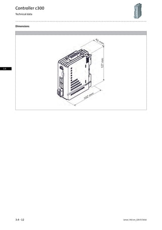
Dimensions
127 x 42 x 102[mm]h x b x t
Mass
0.33[kg]m
3.4 - 11Lenze | V02-en_GB-07/2016
Controller c300
Technical data
3.4](https://image.slidesharecdn.com/catalogue-lenzefastmotioncontrolsolutionsportfolio-160730160451/85/Catalogue-Lenze-FAST-motion-control-solutions-portfolio-77-320.jpg)
![SD card and USB flash drive
SD cards and USB flash drives are available for data storage and data
backups.
ƒ A SD card is part of the scope of supply of the controller.
ƒ SD card without Application Credit.
Product keyFeaturesMode
Application Credit 0 • 512 MB
EPCZEMUS4
USB flash drive
• 1 GB
EPCZEMUS6• 4 GB
24 V power supply unit
An external power supply unit is also available as an alternative for
powering the controller's control electronics.
24 V power supply unit
Rated data
Product key
EZV2400-000
Rated voltage
230[V]UN, ACAC
Rated mains current
1.20[A]IN, AC
Output voltage
DC 22.5 ...28.5[V]Uout
Rated current
10.0[A]IN
Dimensions
130 x 85 x 125[mm]h x b x t
Mass
1.24[kg]m
3.4 - 17Lenze | V02-en_GB-07/2016
Controller c300
Technical data
3.4](https://image.slidesharecdn.com/catalogue-lenzefastmotioncontrolsolutionsportfolio-160730160451/85/Catalogue-Lenze-FAST-motion-control-solutions-portfolio-83-320.jpg)


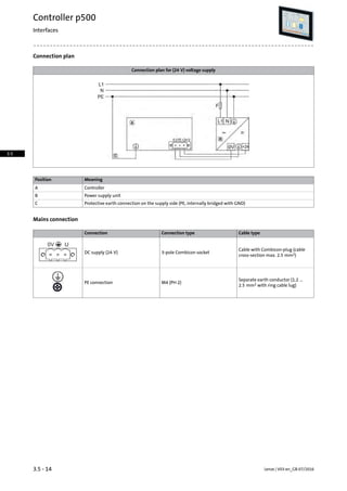
![Standards and operating conditions
Mode
p500Controller
Conformity
Low-Voltage DirectiveCE
2014/30/EU
TP TC 020/2011 (TR CU 020/2011)EAC
Approval
Process Control Equipment (File-No. E236341)UL 508C
CSA 22.2 No.142UL/CSA
Degree of protection
IP65 (front)EN 60529
IP20 (back)
Type 1NEMA 250
Climatic conditions
1K3 (Temperature: -5 °C ... +45 °C)Storage (EN 60721-3-1)
2K3 (temperature: -25 °C ... +70 °C)Transport (EN 60721-3-2)
3K3 (temperature: 0 °C ... +55 °C)Operation (EN 60721-3-3)
Degree of pollution
2EN 61131-2
Site altitude
3000[m]HmaxAmsl
Vibration resistance
1 gVibration (EN 61131-2)
15 gMechanical shock (EN 61131-2)
5 Hz ≤ f ≤ 13.2 Hz: ± 1 mm amplitudeOperation (Germanischer Lloyd)
Noise emission
Industrial premisesEN 61000-6-4
Noise immunity
ESD: Severity 3EN 61000-4-2
150 kHz ... 80 MHz, 10 V/m 80 % AM (1 kHz)EN 61000-4-6
80 kHz ... 1000 MHz, 10 V/m 80 % AM (1 kHz)EN 61000-4-3
1.4 GHz ... 2.0 GHz, 3 V/m, 80 % AM (1kHz)
2.0 GHz ... 2.7 GHz, 1 V/m, 80 % AM (1kHz)
Burst: Severity 3EN 61000-4-4
Lenze | V03-en_GB-07/20163.5 - 10
Controller p500
Technical data
3.5](https://image.slidesharecdn.com/catalogue-lenzefastmotioncontrolsolutionsportfolio-160730160451/85/Catalogue-Lenze-FAST-motion-control-solutions-portfolio-96-320.jpg)
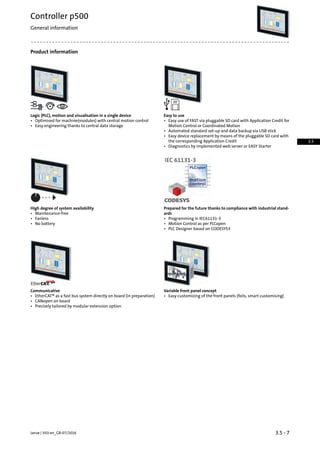
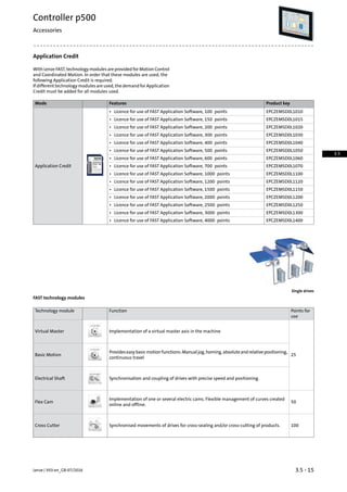
![Rated data
Mode
p500Controller
Display
38.126.417.8[cm]Screen diagonal
15.010.47.0[]
TFTDisplay
colorDesign
GraphicsType
262144Number of colours
1024 x 768800 x 600800 x 480[Pixel]Resolution
400320[cd/m2]Brightness
1 : 7001 : 400Contrast
Operator control
Resistive touchscreenScreen
Processor type
Intel® Atom™ 1.75 GHzFanless
Storage medium
512[MB]SD card1)
Interfaces
2Ethernet (integrated switch)
1EtherCAT
2USB
Interface connection for PROFINET-Device (MC-PND)Option
Interface connection for CANopen (MC-CAN2)
Interface connection for PROFIBUS Master (MC-PBM)
Interface connection for RS232, 422, 485 (MC-ISI)
-
Supply voltage
24[V]± 25 %UinDC
Max. current consumption
0.702)0.602)0.502)[A]Imax
1.503)1.303)1.203)
Operating system
Windows® CE 6.0
1 x SD card included in the scope of supply.1)
Without optional cards and USB load.2)
2x 500 mA USB 1+2, with MC-CAN2 module, 30 s max. after switching-on.3)
3.5 - 11Lenze | V03-en_GB-07/2016
Controller p500
Technical data
3.5](https://image.slidesharecdn.com/catalogue-lenzefastmotioncontrolsolutionsportfolio-160730160451/85/Catalogue-Lenze-FAST-motion-control-solutions-portfolio-97-320.jpg)
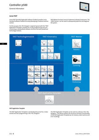
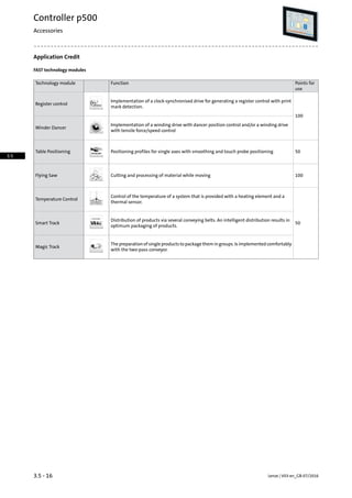
![Rated data
Mode
p500Controller
Display
38.126.417.8[cm]Screen diagonal
15.010.47.0[]
Memory size
512[MB]Program memory
4000[MB]Data memory
4[kB]Flags
1024[kB]Retain data
10000Max. number of persistently saved
visualisation alarms
2[GB]Main memory (RAM)
4[GB]Min. internal flash memory
Runtime
●FAST Runtime1)
●Visualisation
Dimensions
310 x 390 x 93240 x 282 x 86155 x 210 x 86[mm]h x b x t
Mass
4.502.501.40[kg]m
Optional1)
Lenze | V03-en_GB-07/20163.5 - 12
Controller p500
Technical data
3.5](https://image.slidesharecdn.com/catalogue-lenzefastmotioncontrolsolutionsportfolio-160730160451/85/Catalogue-Lenze-FAST-motion-control-solutions-portfolio-98-320.jpg)
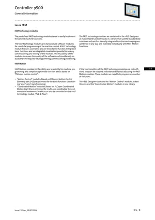
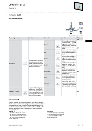
![Dimensions
DimensionsDisplay
Screen diagonal
e3e2e1b2b1ba2a1a
[mm][mm][mm][mm][mm][mm][mm][mm][mm][][cm]
22.04.0082.01041361551821912107.017.8
22.04.0082.010422124018226328210.426.4
27.06.0087.010429131018237139015.038.1
3.5 - 13Lenze | V03-en_GB-07/2016
Controller p500
Technical data
3.5](https://image.slidesharecdn.com/catalogue-lenzefastmotioncontrolsolutionsportfolio-160730160451/85/Catalogue-Lenze-FAST-motion-control-solutions-portfolio-99-320.jpg)
![SD card and USB flash drive
SD cards and USB flash drives are available for data storage and data
backups.
ƒ A SD card is part of the scope of supply of the controller.
ƒ SD card without Application Credit.
Product keyFeaturesMode
Application Credit 0 • 512 MB
EPCZEMUS4
USB flash drive
• 1 GB
EPCZEMUS6• 4 GB
24 V power supply unit
An external power supply unit is also available as an alternative for
powering the controller's control electronics.
24 V power supply unit
Rated data
Product key
EZV2400-000
Rated voltage
230[V]UN, ACAC
Rated mains current
1.20[A]IN, AC
Output voltage
DC 22.5 ...28.5[V]Uout
Rated current
10.0[A]IN
Dimensions
130 x 85 x 125[mm]h x b x t
Mass
1.24[kg]m
3.5 - 19Lenze | V03-en_GB-07/2016
Controller p500
Accessories
3.5](https://image.slidesharecdn.com/catalogue-lenzefastmotioncontrolsolutionsportfolio-160730160451/85/Catalogue-Lenze-FAST-motion-control-solutions-portfolio-105-320.jpg)

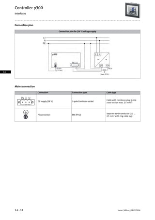
![Standards and operating conditions
Mode
p300Controller
Conformity
Low-Voltage DirectiveCE
2014/30/EU
TP TC 020/2011 (TR CU 020/2011)EAC
Approval
Process Control Equipment (File-No. E236341)UL 508C
CSA C22.2 No. 61010-2-201UL/CSA
UL 61010-2-201
Degree of protection
IP65 (front)EN 60529
IP20 (back)
Type 4NEMA 250
Climatic conditions
1K3 (Temperature: -5 °C ... +45 °C)Storage (EN 60721-3-1)
2K3 (temperature: -25 °C ... +70 °C)Transport (EN 60721-3-2)
3K3 (temperature: 0 °C ... +55 °C)Operation (EN 60721-3-3)
Degree of pollution
2EN 61131-2
Site altitude
2000[m]HmaxAmsl
Vibration resistance
1 gVibration (EN 61131-2)
15 gMechanical shock (EN 61131-2)
Noise emission
Industrial premisesEN 61000-6-4
Noise immunity
ESD: Severity 3EN 61000-4-2
150 kHz ... 80 MHz, 10 V/m 80 % AM (1 kHz)EN 61000-4-6
80 kHz ... 1000 MHz, 10 V/m 80 % AM (1 kHz)EN 61000-4-3
1.4 GHz ... 2.0 GHz, 3 V/m, 80 % AM (1kHz)
2.0 GHz ... 2.7 GHz, 1 V/m, 80 % AM (1kHz)
Burst: Severity 3EN 61000-4-4
Lenze | V02-en_GB-07/20163.6 - 8
Controller p300
Technical data
3.6](https://image.slidesharecdn.com/catalogue-lenzefastmotioncontrolsolutionsportfolio-160730160451/85/Catalogue-Lenze-FAST-motion-control-solutions-portfolio-114-320.jpg)
![Rated data
Mode
p300Controller
Display
26.417.810.9[cm]Screen diagonal
10.47.04.3[]
TFTDisplay
colorDesign
GraphicsType
262144Number of colours
800 x 600800 x 480480 x 272[Pixel]Resolution
400320400[cd/m2]Brightness
1 : 7001 : 400Contrast
Operator control
Resistive touchscreenScreen
Processor type
ARM Cortex A8800Fanless
Storage medium
512[MB]SD card
Interfaces
1Ethernet
1EtherCAT Master
1CANopen
1USB
Interface connection for CANopen (MC-CAN2)Option1)
Supply voltage
24[V]± 25 %UinDC
Max. current consumption
0.950.900.85[A]Imax
Operating system
Windows® Embedded Compact 7
In preparation.1)
3.6 - 9Lenze | V02-en_GB-07/2016
Controller p300
Technical data
3.6](https://image.slidesharecdn.com/catalogue-lenzefastmotioncontrolsolutionsportfolio-160730160451/85/Catalogue-Lenze-FAST-motion-control-solutions-portfolio-115-320.jpg)
![Rated data
Mode
p300Controller
Display
26.417.810.9[cm]Screen diagonal
10.47.04.3[]
Memory size
128[kB]Retain data
512[MB]Main memory (RAM)
2[GB]Min. internal flash memory
Runtime
●FAST Runtime1)
Dimensions
282 x 240 x 51210 x 155 x 51130 x 104 x 45[mm]h x b x t
Mass
2.101.100.53[kg]m
Optional1)
Lenze | V02-en_GB-07/20163.6 - 10
Controller p300
Technical data
3.6](https://image.slidesharecdn.com/catalogue-lenzefastmotioncontrolsolutionsportfolio-160730160451/85/Catalogue-Lenze-FAST-motion-control-solutions-portfolio-116-320.jpg)
![Dimensions
DimensionsDisplay
Screen diagonal
e3e2e1b1ba2a1a
[mm][mm][mm][mm][mm][mm][mm][mm][][cm]
3.0042.091.01041171171304.310.9
22.03.0047.01361551171912107.017.8
22.04.0047.022124011726328210.426.4
3.6 - 11Lenze | V02-en_GB-07/2016
Controller p300
Technical data
3.6](https://image.slidesharecdn.com/catalogue-lenzefastmotioncontrolsolutionsportfolio-160730160451/85/Catalogue-Lenze-FAST-motion-control-solutions-portfolio-117-320.jpg)
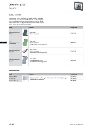
![SD card and USB flash drive
SD cards and USB flash drives are available for data storage and data
backups.
ƒ A SD card is part of the scope of supply of the controller.
ƒ SD card without Application Credit.
Product keyFeaturesMode
Application Credit 0 • 512 MB
EPCZEMUS4
USB flash drive
• 1 GB
EPCZEMUS6• 4 GB
24 V power supply unit
An external power supply unit is also available as an alternative for
powering the controller's control electronics.
24 V power supply unit
Rated data
Product key
EZV2400-000
Rated voltage
230[V]UN, ACAC
Rated mains current
1.20[A]IN, AC
Output voltage
DC 22.5 ...28.5[V]Uout
Rated current
10.0[A]IN
Dimensions
130 x 85 x 125[mm]h x b x t
Mass
1.24[kg]m
3.6 - 13Lenze | V02-en_GB-07/2016
Controller p300
Accessories
3.6](https://image.slidesharecdn.com/catalogue-lenzefastmotioncontrolsolutionsportfolio-160730160451/85/Catalogue-Lenze-FAST-motion-control-solutions-portfolio-119-320.jpg)

![Standards and operating conditions
Conformity
Low-Voltage DirectiveCE
2006/95/EC
TP TC 020/2011 (TR CU 020/2011)EAC
Approval
Programmable Controller (File-No. E343358)UL 508C
Degree of protection
IP20EN 60529
Climatic conditions
Temperature: -25 °C ... +70 °CStorage (EN 60068-2-14)
Temperature: -25 °C ... +70 °CTransport (EN 60068-14)
Temperature: 0 °C ... +60 °COperation (EN 61131-2)
Site altitude
3000[m]HmaxAmsl
Vibration resistance
1 gVibration (EN 60068-2-6)
15 gMechanical shock (EN 60068-2-27)
Noise emission
Limit class AEN 61000-6-4
Noise immunity
ESD: Severity 3EN 61000-4-2
150 kHz ... 80 MHz, 10 V/m 80% AM (1 kHz)EN 61000-4-6
80 kHz ... 1000 MHz, 10 V/m 80% AM (1 kHz)EN 61000-4-3
Burst: Severity 3EN 61000-4-4
Surge: Severity 3EN 61000-4-5
Insulation resistance
Overvoltage category IIIIEC 61131-2
Above 2000 m amsl overvoltage category II
Insulation voltage to reference
earth/PE
500[V]UACEN 61800-5-1
Electrical isolation
500 V between I/O supply, electronic supply and fieldbus
Protective insulation of control cir-
cuits
Safe mains isolation: double/reinforced insulationEN 61800-5-1
Lenze | V02-en_GB-07/20163.7 - 10
I/O System 1000
Technical data - General
3.7](https://image.slidesharecdn.com/catalogue-lenzefastmotioncontrolsolutionsportfolio-160730160451/85/Catalogue-Lenze-FAST-motion-control-solutions-portfolio-132-320.jpg)
![Rated data
Product key
EPM-S130EPM-S120EPM-S110
Mode
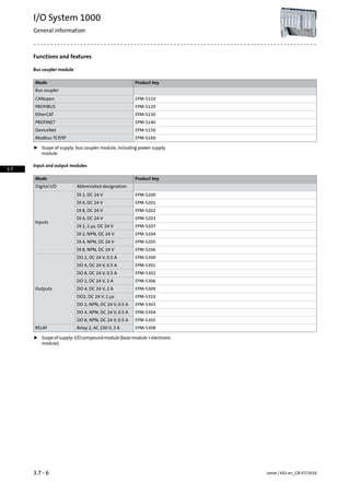
EtherCATPROFIBUSCANopenBus coupler
Rated voltage
24[V]UN, DCDC
Max. input current
0.950.900.95[A]Iin,max
Output current
3[A]IoutBackplane bus
71)[A]IoutI/O supply
Output voltage
24[V]UoutI/O supply
Max. number of I/O modules
64
Diagnostics
Supply OK / fuse defectiveVoltage supply
Ready for operationRUN-LED as per CANopenBus diagnostics
System errorReady for operation
System error
Fusing
Via power supply module
Communication
EtherCAT (CoE)PROFIBUS-DP-V0CANopen, DS301 V4.02Communication profile
PROFIBUS-DP-V1
Node
Slave
Baud rate
100 Mbps9.6 kbps ... 12 Mbps10 kbps ... 1 Mbpsb
Number of bus nodes
Max. 65535With repeaters: 125127
Without repeaters: 32
Number of PDOs
4 kbytes244 bytes16 Rx / 16 Tx
Device description file
XML (Modular Device Profile
MDP)
GSEEDS
Can used up to 10 A without UL-approval.1)
3.7 - 11Lenze | V02-en_GB-07/2016
I/O System 1000
Technical data - Bus coupler
3.7](https://image.slidesharecdn.com/catalogue-lenzefastmotioncontrolsolutionsportfolio-160730160451/85/Catalogue-Lenze-FAST-motion-control-solutions-portfolio-133-320.jpg)
![Rated data
Product key
EPM-S130EPM-S120EPM-S110
Mode
EtherCATPROFIBUSCANopenBus coupler
Connection
RJ45, doubleSub-D connection, 9-pin
Dimensions
109 x 48 x 76.5[mm]h x b x t
Mass
0.16[kg]m
Product key
EPM-S130EPM-S120EPM-S110
Lenze | V02-en_GB-07/20163.7 - 12
I/O System 1000
Technical data - Bus coupler
3.7](https://image.slidesharecdn.com/catalogue-lenzefastmotioncontrolsolutionsportfolio-160730160451/85/Catalogue-Lenze-FAST-motion-control-solutions-portfolio-134-320.jpg)
![Rated data
Product key
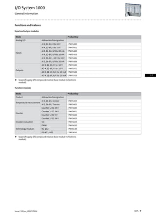
EPM-S160EPM-S150EPM-S140
Mode
Modbus TCP/IPDeviceNetPROFINETBus coupler
Rated voltage
24[V]UN, DCDC
Max. input current
0.95[A]Iin,max
Output current
3[A]IoutBackplane bus
71)[A]IoutI/O supply
Output voltage
24[V]UoutI/O supply
Max. number of I/O modules
64
Diagnostics
Supply OK / fuse defectiveVoltage supply
Ready for operationBus diagnostics
System error
Fusing
Via power supply module
Communication
Modbus TCP/IPDeviceNetPROFINET (RT/IRT)Communication profile
Node
SlaveDevice
Baud rate
100 Mbps500 kbps100 Mbpsb
Number of bus nodes
64255
Number of PDOs
1 kbytes256 bytes512 bytes
Device description file
EDSGSDML
Can used up to 10 A without UL-approval.1)
3.7 - 13Lenze | V02-en_GB-07/2016
I/O System 1000
Technical data - Bus coupler
3.7](https://image.slidesharecdn.com/catalogue-lenzefastmotioncontrolsolutionsportfolio-160730160451/85/Catalogue-Lenze-FAST-motion-control-solutions-portfolio-135-320.jpg)
![Rated data
Product key
EPM-S160EPM-S150EPM-S140
Mode
Modbus TCP/IPDeviceNetPROFINETBus coupler
Connection
RJ45Pluggable terminal 5-poleRJ45, double
Dimensions
109 x 48 x 76.5[mm]h x b x t
Mass
0.16[kg]m
Product key
EPM-S160EPM-S150EPM-S140
Lenze | V02-en_GB-07/20163.7 - 14
I/O System 1000
Technical data - Bus coupler
3.7](https://image.slidesharecdn.com/catalogue-lenzefastmotioncontrolsolutionsportfolio-160730160451/85/Catalogue-Lenze-FAST-motion-control-solutions-portfolio-136-320.jpg)
![Rated data
ƒ Positive switching
Product key
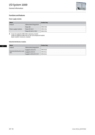
EPM-S202EPM-S201EPM-S200
Mode
DI 8, DC 24 VDI 4, DC 24 VDI 2, DC 24 VAbbreviated designation
Digital inputs
842Number
3[ms]Input filter delay time
1-wire technology1-/2-wire technology1-/2-/3-wire technologyConnection system
IEC 61121-2 type 1Input level
0: 0 ... 5 V
1: 15 ... 28.8 V
PNPWiring
Input current
6055[mA]IinBackplane bus
Rated voltage
24[V]UN, DCDC
Communication
8 bits8 bits8 bitsWidth in the input process image
4 bits with bus coupler
EPM-S110
2 bits with bus coupler
EPM-S110
Parameter data (PROFIB-
US/PROFINET)
Diagnostics
Ready for operation / errorModule status
1 LED per channelSignal status
Time stamp
Dimensions
109 x 12.5 x 76.5[mm]h x b x t
Mass
0.060[kg]m
Product key
EPM-S202EPM-S201EPM-S200
3.7 - 15Lenze | V02-en_GB-07/2016
I/O System 1000
Technical data - Digital inputs
3.7](https://image.slidesharecdn.com/catalogue-lenzefastmotioncontrolsolutionsportfolio-160730160451/85/Catalogue-Lenze-FAST-motion-control-solutions-portfolio-137-320.jpg)
![Rated data
ƒ Positive switching
Product key
EPM-S207EPM-S203
Mode
DI 2, 2 µs, DC 24 VDI 4, DC 24 VAbbreviated designation
Digital inputs
24Number
0.002 ... 33[ms]Input filter delay time
1-/2-/3-wire technologyConnection system
IEC 61121-2 type 1Input level
0: 0 ... 5 V
1: 15 ... 28.8 V
PNPWiring
Input current
8555[mA]IinBackplane bus
Rated voltage
24[V]UN, DCDC
Communication
4 ... 60 bytes8 bitsWidth in the input process image
4 bits with bus coupler EPM-S110
6 bytesParameter data (PROFIB-
US/PROFINET)
Diagnostics
Ready for operation / errorModule status
1 LED per channelSignal status
YesTime stamp
Dimensions
109 x 12.5 x 76.5[mm]h x b x t
Mass
0.060[kg]m
Product key
EPM-S207EPM-S203
Lenze | V02-en_GB-07/20163.7 - 16
I/O System 1000
Technical data - Digital inputs
3.7](https://image.slidesharecdn.com/catalogue-lenzefastmotioncontrolsolutionsportfolio-160730160451/85/Catalogue-Lenze-FAST-motion-control-solutions-portfolio-138-320.jpg)
![Rated data
ƒ Negative switching
Product key
EPM-S206EPM-S205EPM-S204
Mode
DI 8, NPN, DC 24 VDI 4, NPN, DC 24 VDI 2, NPN, DC 24 VAbbreviated designation
Digital inputs
842Number
3[ms]Input filter delay time
1-wire technology1-/2-wire technology1-/2-/3-wire technologyConnection system
IEC 61121-2 type 1Input level
0: 0 ... 5 V
1: 15 ... 28.8 V
NPNWiring
Input current
6560[mA]IinBackplane bus
Rated voltage
24[V]UN, DCDC
Communication
8 bits8 bits8 bitsWidth in the input process image
4 bits with bus coupler
EPM-S110
2 bits with bus coupler
EPM-S110
Diagnostics
Ready for operation / errorModule status
1 LED per channelSignal status
Time stamp
Dimensions
109 x 12.5 x 76.5[mm]h x b x t
Mass
0.060[kg]m
Product key
EPM-S206EPM-S205EPM-S204
3.7 - 17Lenze | V02-en_GB-07/2016
I/O System 1000
Technical data - Digital inputs
3.7](https://image.slidesharecdn.com/catalogue-lenzefastmotioncontrolsolutionsportfolio-160730160451/85/Catalogue-Lenze-FAST-motion-control-solutions-portfolio-139-320.jpg)
![Rated data
ƒ Positive switching
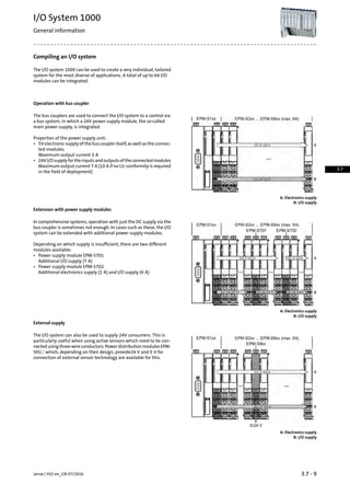
Product key
EPM-S302EPM-S301EPM-S300
Mode
DO 8, DC 24 V, 0.5 ADO 4, DC 24 V, 0.5 ADO 2, DC 24 V, 0.5 AAbbreviated designation
Digital outputs
842Number
30 ... 175[µs]TOutput filter delay time
1-wire technology1-/2-wire technology1-/2-/3-wire technologyConnection system
PNPWiring
Input current
6555[mA]IinBackplane bus
151)101)51)[mA]IinI/O supply
Output current
0.50[A]Ioutper channel
Rated voltage
24[V]UN, DCDC
Switching frequency
1000[Hz]fchOhmic load
0.50[Hz]fchInductive load
10.0[Hz]fchLamp load
Communication
Width in the input process image
8 bits8 bits8 bitsWidth in the output process image
4 bits with bus coupler
EPM-S110
2 bits with bus coupler
EPM-S110
Parameter data (PROFIB-
US/PROFINET)
+ load current.1)
Lenze | V02-en_GB-07/20163.7 - 18
I/O System 1000
Technical data - Digital outputs
3.7](https://image.slidesharecdn.com/catalogue-lenzefastmotioncontrolsolutionsportfolio-160730160451/85/Catalogue-Lenze-FAST-motion-control-solutions-portfolio-140-320.jpg)
![Rated data
ƒ Positive switching
Product key
EPM-S302EPM-S301EPM-S300
Mode
DO 8, DC 24 V, 0.5 ADO 4, DC 24 V, 0.5 ADO 2, DC 24 V, 0.5 AAbbreviated designation
Diagnostics
Ready for operation / error / overloadModule status
1 LED per channelSignal status
Short-circuit strength
Electronic
Dimensions
109 x 12.5 x 76.5[mm]h x b x t
Mass
0.060[kg]m
Product key
EPM-S302EPM-S301EPM-S300
3.7 - 19Lenze | V02-en_GB-07/2016
I/O System 1000
Technical data - Digital outputs
3.7](https://image.slidesharecdn.com/catalogue-lenzefastmotioncontrolsolutionsportfolio-160730160451/85/Catalogue-Lenze-FAST-motion-control-solutions-portfolio-141-320.jpg)
![Rated data
ƒ Positive switching
Product key
EPM-S310EPM-S309EPM-S306
Mode
DO2, DC 24 V, 1 µsDO 4, DC 24 V, 2 ADO 2, DC 24 V, 2 AAbbreviated designation
Digital outputs
242Number
130 ... 175[µs]TOutput filter delay time
1-/2-wire technology1-/2-/3-wire technologyConnection system
PNPWiring
Input current
8555[mA]IinBackplane bus
141)101)51)[mA]IinI/O supply
Output current
0.502.002)[A]Ioutper channel
Rated voltage
24[V]UN, DCDC
Switching frequency
400001000[Hz]fchOhmic load
400000.50[Hz]fchInductive load
4000010.0[Hz]fchLamp load
Communication
4 bytesWidth in the input process image
4 ... 60 bytes8 bits8 bitsWidth in the output process image
4 bits with bus coupler
EPM-S110
2 bits with bus coupler
EPM-S110
2 bytesParameter data (PROFIB-
US/PROFINET)
+ load current.1)
On the EPM-S309, the max. total current is 4 A.2)
Lenze | V02-en_GB-07/20163.7 - 20
I/O System 1000
Technical data - Digital outputs
3.7](https://image.slidesharecdn.com/catalogue-lenzefastmotioncontrolsolutionsportfolio-160730160451/85/Catalogue-Lenze-FAST-motion-control-solutions-portfolio-142-320.jpg)
![Rated data
ƒ Positive switching
Product key
EPM-S310EPM-S309EPM-S306
Mode
DO2, DC 24 V, 1 µsDO 4, DC 24 V, 2 ADO 2, DC 24 V, 2 AAbbreviated designation
Diagnostics
Ready for operation / error / overloadModule status
1 LED per channelSignal status
Short-circuit strength
Electronic
Dimensions
109 x 12.5 x 76.5[mm]h x b x t
Mass
0.060[kg]m
Product key
EPM-S310EPM-S309EPM-S306
3.7 - 21Lenze | V02-en_GB-07/2016
I/O System 1000
Technical data - Digital outputs
3.7](https://image.slidesharecdn.com/catalogue-lenzefastmotioncontrolsolutionsportfolio-160730160451/85/Catalogue-Lenze-FAST-motion-control-solutions-portfolio-143-320.jpg)
![Rated data
ƒ Negative switching
Product key
EPM-S305EPM-S304EPM-S303
Mode
DO 8, NPN, DC 24 V, 0.5 ADO 4, NPN, DC 24 V, 0.5 ADO 2, NPN, DC 24 V, 0.5 AAbbreviated designation
Digital outputs
842Number
30 ... 175[µs]TOutput filter delay time
1-wire technology1-/2-wire technology1-/2-/3-wire technologyConnection system
NPNWiring
Input current
706560[mA]IinBackplane bus
101)51)31)[mA]IinI/O supply
Output current
0.50[A]Ioutper channel
Rated voltage
24[V]UN, DCDC
Switching frequency
1000[Hz]fchOhmic load
0.50[Hz]fchInductive load
10.0[Hz]fchLamp load
Communication
8 bits8 bits8 bitsWidth in the output process image
4 bits with bus coupler
EPM-S110
2 bits with bus coupler
EPM-S110
+ load current.1)
Lenze | V02-en_GB-07/20163.7 - 22
I/O System 1000
Technical data - Digital outputs
3.7](https://image.slidesharecdn.com/catalogue-lenzefastmotioncontrolsolutionsportfolio-160730160451/85/Catalogue-Lenze-FAST-motion-control-solutions-portfolio-144-320.jpg)
![Rated data
ƒ Negative switching
Product key
EPM-S305EPM-S304EPM-S303
Mode
DO 8, NPN, DC 24 V, 0.5 ADO 4, NPN, DC 24 V, 0.5 ADO 2, NPN, DC 24 V, 0.5 AAbbreviated designation
Diagnostics
Ready for operation / error / overloadModule status
1 LED per channelSignal status
Short-circuit strength
Electronic
Dimensions
109 x 12.5 x 76.5[mm]h x b x t
Mass
0.060[kg]m
Product key
EPM-S305EPM-S304EPM-S303
+ load current.1)
3.7 - 23Lenze | V02-en_GB-07/2016
I/O System 1000
Technical data - Relay
3.7](https://image.slidesharecdn.com/catalogue-lenzefastmotioncontrolsolutionsportfolio-160730160451/85/Catalogue-Lenze-FAST-motion-control-solutions-portfolio-145-320.jpg)
![Rated data
Product key
EPM-S308
Mode
Relay 2, AC 230 V, 3 AAbbreviated designation
Relay outputs
2Number
NO contactContact
Input current
55[mA]IinBackplane bus
Rated voltage
30[V]UN, DCDC
230[V]UN, ACAC
Output current
3.00[A]Ioutper channel
Switching frequency
100[Hz]fchOhmic load
Communication
8 bitsWidth in the output process image
2 bits with bus coupler EPM-S110
Diagnostics
Ready for operation / errorModule status
1 LED per channelSignal status
Dimensions
109 x 12.5 x 76.5[mm]h x b x t
Mass
0.060[kg]m
Product key
EPM-S308
Lenze | V02-en_GB-07/20163.7 - 24
I/O System 1000
Technical data - Relay
3.7](https://image.slidesharecdn.com/catalogue-lenzefastmotioncontrolsolutionsportfolio-160730160451/85/Catalogue-Lenze-FAST-motion-control-solutions-portfolio-146-320.jpg)
![Rated data
Product key
EPM-S402EPM-S401EPM-S400
Mode
AI 2, 12-bit, 0/4 to 20 mAAI 4, 12-bit, 0 to 10 VAI 2, 12-bit, 0 to 10 VAbbreviated designation
Analog inputs
242Number
0 …10[V]UDCVoltage
0 … 20[mA]ICurrent
4 … 20
1.00[kHz]Input filter limit frequency
12 bitsResolution
± 0.3 at 0 ... 20 mA± 0.3[%]Usage error limit
± 0.5 at 4 ... 20 mA
± 0.2 at 0 ... 20 mA± 0.2[%]Basic error limit (at 25 °C)
± 0.3 at 4 ... 20 mA
4 (all channels)8 (all channels)4 (all channels)[ms]TA/D conversion time
Input current
70[mA]IinBackplane bus
15[mA]IinI/O supply
Rated voltage
[V]UN, DCDC
Communication
4 bytes8 bytes4 bytesWidth in the input process image
6 bytes8 bytes6 bytesParameter data (PROFIB-
US/PROFINET)
Diagnostics
Ready for operation / errorModule status
1 LED per channelSignal status
Dimensions
109 x 12.5 x 76.5[mm]h x b x t
Mass
0.060[kg]m
Product key
EPM-S402EPM-S401EPM-S400
3.7 - 25Lenze | V02-en_GB-07/2016
I/O System 1000
Technical data - Analog inputs
3.7](https://image.slidesharecdn.com/catalogue-lenzefastmotioncontrolsolutionsportfolio-160730160451/85/Catalogue-Lenze-FAST-motion-control-solutions-portfolio-147-320.jpg)
![Rated data
Product key
EPM-S408EPM-S406EPM-S403
Mode
AI 2, 16-bit, 0/4 to 20 mAAI 2, 16-bit , -10 V to 10 VAI 4, 12-bit, 0/4 to 20 mAAbbreviated designation
Analog inputs
24Number
-10 ... 10[V]UDCVoltage
0 … 200 … 20[mA]ICurrent
4 … 204 … 20
1.00[kHz]Input filter limit frequency
16 bits12 bitsResolution
± 0.2± 0.3 at 0 ... 20 mA[%]Usage error limit
± 0.5 at 4 ... 20 mA
± 0.1± 0.2 at 0 ... 20 mA[%]Basic error limit (at 25 °C)
± 0.3 at 4 ... 20 mA
0.24 (all channels)8 (all channels)[ms]TA/D conversion time
Input current
6070[mA]IinBackplane bus
152015[mA]IinI/O supply
Rated voltage
[V]UN, DCDC
Communication
4 bytes8 bytesWidth in the input process image
20 bytes8 bytesParameter data (PROFIB-
US/PROFINET)
Diagnostics
Ready for operation / errorModule status
1 LED per channelSignal status
Dimensions
109 x 12.5 x 76.5[mm]h x b x t
Mass
0.060[kg]m
Product key
EPM-S408EPM-S406EPM-S403
Lenze | V02-en_GB-07/20163.7 - 26
I/O System 1000
Technical data - Analog inputs
3.7](https://image.slidesharecdn.com/catalogue-lenzefastmotioncontrolsolutionsportfolio-160730160451/85/Catalogue-Lenze-FAST-motion-control-solutions-portfolio-148-320.jpg)
![Rated data
Product key
EPM-S503EPM-S502EPM-S501EPM-S500
Mode
AO 4, 12-bit, 0/4 to
20 mA
AO 2, 12-bit, 0/4 to
20 mA
AO 4, 12-bit, 0 to
10 V
AO 2, 12-bit, 0 to
10 V
Abbreviated designation
Analog outputs
4242Number
0 … 10[V]UDCVoltage
0/4 … 20[mA]ICurrent
12 bitsResolution
± 0.4 at 0 ... 20 mA± 0.3[%]Usage error limit
± 0.5 at 4 ... 20 mA
± 0.2 at 0 ... 20 mA± 0.2[%]Basic error limit (at 25 °C)
± 0.3 at 4 ... 20 mA
2 (all channels)[ms]TD/A conversion time
Input current
80[mA]IinBackplane bus
955535[mA]IinI/O supply
Rated voltage
[V]UN, DCDC
Communication
8 bytes4 bytes8 bytes4 bytesWidth in the input process image
10 bytes8 bytes10 bytes8 bytesParameter data (PROFIB-
US/PROFINET)
Diagnostics
Ready for operation / errorModule status
1 LED per channelSignal status
(overload, short circuit, parameter entry error)
Dimensions
109 x 12.5 x 76.5[mm]h x b x t
Mass
0.060[kg]m
Product key
EPM-S503EPM-S502EPM-S501EPM-S500
3.7 - 27Lenze | V02-en_GB-07/2016
I/O System 1000
Technical data - Analog outputs
3.7](https://image.slidesharecdn.com/catalogue-lenzefastmotioncontrolsolutionsportfolio-160730160451/85/Catalogue-Lenze-FAST-motion-control-solutions-portfolio-149-320.jpg)
![Rated data
Product key
EPM-S405EPM-S404
Mode
AI 2, 16-bit, ThermoAI 4, 16-bit, resistorAbbreviated designation
Analog inputs
24 / (2)Number
[V]UDCVoltage
16 bitsResolution
± 0.4[%]Usage error limit
≥ ± 1.51)[K]
± 0.2[%]Basic error limit (at 25 °C)
≥ ± 1.01)[K]
4 ... 3252)[ms]TA/D conversion time
2-wiretechnology(3-/4-wiretechnology)Connection system
Input current
75[mA]IinBackplane bus
30[mA]IinI/O supply
Temperature sensor
Thermocouple type:Resistor
Thermocouple type: J, K, N, R, S, T, B, C,
E, L
PT100, PT1000
NI100, NI1000
NI120
Communication
4 bytes8 bytesWidth in the input process image
22 bytes34 bytesParameter data (PROFIB-
US/PROFINET)
Diagnostics
Ready for operation / errorModule status
1 LED per channelSignal status
Dimensions
109 x 12.5 x 76.5[mm]h x b x t
Mass
0.060[kg]m
Product key
EPM-S405EPM-S404
Dependent on the sensor and interference frequency suppression.1)
Dependent on the configuration and filter settings.2)
Lenze | V02-en_GB-07/20163.7 - 28
I/O System 1000
Technical data - Temperature measurement
3.7](https://image.slidesharecdn.com/catalogue-lenzefastmotioncontrolsolutionsportfolio-160730160451/85/Catalogue-Lenze-FAST-motion-control-solutions-portfolio-150-320.jpg)
![Measuring range
Product key
EPM-S405EPM-S404
Sensor measuring range
-200 ... 850[°C]TPT100
-200 ... 850[°C]TPT1000
-60 ... 250[°C]TNI100
-60 ... 250[°C]TNI1000
60/600/3000/6000[Ω]RResistor
0 ... 1820[°C]TThermocouple type B
0 ... 2315[°C]TThermocouple type C
-270 ... 1000[°C]TThermocouple type E
-210 ... 1200[°C]TThermocouple type J
-270 ... 1372[°C]TThermocouple type K
-200 ... 900[°C]TThermocouple type L
-270 ... 1300[°C]TThermocouple type N
-50 ... 1769[°C]TThermocouple type R
-50 ... 1769[°C]TThermocouple type S
-270 ... 400[°C]TThermocouple type T
-80 … 80[mV]UDCVoltage
3.7 - 29Lenze | V02-en_GB-07/2016
I/O System 1000
Technical data - Temperature measurement
3.7](https://image.slidesharecdn.com/catalogue-lenzefastmotioncontrolsolutionsportfolio-160730160451/85/Catalogue-Lenze-FAST-motion-control-solutions-portfolio-151-320.jpg)
![Rated data
Product key
EPM-S601EPM-S600
Mode
Counter 2, DC 24 VCounter 1, DC 24 VAbbreviated designation
Digital inputs
21Number
HTLInput level
100[kHz]Input filter limit frequency
32[Bit]Counter width
400[kHz]Counting frequency
Digital outputs
1Number
Input current
75[mA]IinBackplane bus
151)201)[mA]IinI/O supply
Output current
0.50[A]Ioutper channel
Rated voltage
24[V]UN, DCDC
Communication
12 bytesWidth in the input process image
12 bytes10 bytesWidth in the output process image
42 bytes21 bytesParameter data (PROFIB-
US/PROFINET)
+ encoder power consumption.1)
Lenze | V02-en_GB-07/20163.7 - 30
I/O System 1000
Technical data - Counters
3.7](https://image.slidesharecdn.com/catalogue-lenzefastmotioncontrolsolutionsportfolio-160730160451/85/Catalogue-Lenze-FAST-motion-control-solutions-portfolio-152-320.jpg)
![Rated data
Product key
EPM-S601EPM-S600
Mode
Counter 2, DC 24 VCounter 1, DC 24 VAbbreviated designation
Diagnostics
Ready for operation / errorModule status
1 LED per counter inputSignal status
1 LED per control input
1 LED per output
Counter function
Read, setRead, set
Latch function
Alarm function
Yes
Control inputs
Latch, reset, gate
Dimensions
109 x 12.5 x 76.5[mm]h x b x t
Mass
0.060[kg]m
Product key
EPM-S601EPM-S600
3.7 - 31Lenze | V02-en_GB-07/2016
I/O System 1000
Technical data - Counters
3.7](https://image.slidesharecdn.com/catalogue-lenzefastmotioncontrolsolutionsportfolio-160730160451/85/Catalogue-Lenze-FAST-motion-control-solutions-portfolio-153-320.jpg)
![Rated data
Product key
EPM-S603EPM-S602
Mode
Counter 2, DC 24 VCounter 1, DC 5 VAbbreviated designation
Digital inputs
21Number
HTLTTLInput level
100500[kHz]Input filter limit frequency
32[Bit]Counter width
4002000[kHz]Counting frequency
Digital outputs
Number
Input current
10075[mA]IinBackplane bus
151)201)[mA]IinI/O supply
Output current
[A]Ioutper channel
Rated voltage
[V]UN, DCDC
Communication
12 bytes8 bytesWidth in the input process image
4 bytes10 bytesWidth in the output process image
8 bytes22 bytesParameter data (PROFIB-
US/PROFINET)
+ encoder power consumption.1)
Lenze | V02-en_GB-07/20163.7 - 32
I/O System 1000
Technical data - Counters
3.7](https://image.slidesharecdn.com/catalogue-lenzefastmotioncontrolsolutionsportfolio-160730160451/85/Catalogue-Lenze-FAST-motion-control-solutions-portfolio-154-320.jpg)
![Rated data
Product key
EPM-S603EPM-S602
Mode
Counter 2, DC 24 VCounter 1, DC 5 VAbbreviated designation
Diagnostics
Ready for operation / errorModule status
1 LED per counter inputSignal status
1 LED per control input
1 LED per output
Counter function
ReadRead, set
Alarm function
Yes
Control inputs
Reset
Dimensions
109 x 12.5 x 76.5[mm]h x b x t
Mass
0.060[kg]m
Product key
EPM-S603EPM-S602
3.7 - 33Lenze | V02-en_GB-07/2016
I/O System 1000
Technical data - Counters
3.7](https://image.slidesharecdn.com/catalogue-lenzefastmotioncontrolsolutionsportfolio-160730160451/85/Catalogue-Lenze-FAST-motion-control-solutions-portfolio-155-320.jpg)
![Rated data
Product key
EPM-S650EPM-S640EPM-S620
Mode
RS -422/485RS -232PWMAbbreviated designation
Outputs
2Number
RS 422 / 485RS 232Level
Delay time
1[µs]T
Switching frequency
20[kHz]fch
Input current
10085[mA]IinBackplane bus
101)151)[mA]IinI/O supply
Output current
0.50[A]Ioutper channel
Rated voltage
24[V]UN, DCDC
Communication
RTS/CTSHardware handshake
ASCII, STX/ETX, 3964 (R)Protocols
max. 60 Byte4 bytesWidth in the input process image
max. 60 Byte12 bytesWidth in the output process image
17 bytes8 bytesParameter data (PROFIB-
US/PROFINET)
Max. baud rate
115[kBit/s]b
+ load current.1)
Lenze | V02-en_GB-07/20163.7 - 34
I/O System 1000
Technical data - Technology modules
3.7](https://image.slidesharecdn.com/catalogue-lenzefastmotioncontrolsolutionsportfolio-160730160451/85/Catalogue-Lenze-FAST-motion-control-solutions-portfolio-156-320.jpg)
![Rated data
Product key
EPM-S650EPM-S640EPM-S620
Mode
RS -422/485RS -232PWMAbbreviated designation
Diagnostics
Ready for operation / errorModule status
1 TxD LED, 1 RxD LED1 LED per channelSignal status
Short-circuit strength
Electronic
Dimensions
109 x 12.5 x 76.5[mm]h x b x t
Mass
0.060[kg]m
Product key
EPM-S650EPM-S640EPM-S620
3.7 - 35Lenze | V02-en_GB-07/2016
I/O System 1000
Technical data - Technology modules
3.7](https://image.slidesharecdn.com/catalogue-lenzefastmotioncontrolsolutionsportfolio-160730160451/85/Catalogue-Lenze-FAST-motion-control-solutions-portfolio-157-320.jpg)
![Rated data
Product key
EPM-S604
Mode
SSIAbbreviated designation
Inputs
1Number
RS 422Level
12 … 6000[kHz]finFrequency
Input current
70[mA]IinBackplane bus
30[mA]IinI/O supply
Rated voltage
24[V]UN, DCDC
Communication
6 bytesWidth in the input process image
33 bytesParameter data (PROFIB-
US/PROFINET)
Diagnostics
Ready for operation / errorModule status
1 LED per encoder inputSignal status
3 comparisons, 2 limit valuesEvaluation function
Dimensions
109 x 12.5 x 76.5[mm]h x b x t
Mass
0.060[kg]m
Product key
EPM-S604
Lenze | V02-en_GB-07/20163.7 - 36
I/O System 1000
Technical data - Encoder evaluation
3.7](https://image.slidesharecdn.com/catalogue-lenzefastmotioncontrolsolutionsportfolio-160730160451/85/Catalogue-Lenze-FAST-motion-control-solutions-portfolio-158-320.jpg)
![Rated data
Product key
EPM-S702EPM-S701EPM-S700
Mode
Power DC 24 V / 24 VPower DC 24 VPower BCAbbreviated designation
Rated voltage
24[V]UN, DCDC
Supply voltage
DC 24 (20.4 ... 28.8)DC 24 (20.4 ... 28.8)[V]UinElectronics
Output current
[A]IoutBackplane bus
471)[A]IoutI/O supply
Electrical isolation
not connected to the I/O
supply voltage of the
modules to the left
not connected to the I/O
supply voltage of the
modules to the left
500 V between I/O supply,
electronic supply and
fieldbus
500 V between I/O supply
and electronic supply
Diagnostics
Supply OK / fuse defectiveVoltage supply
Fusing
Internal
Polarity reversal protection
Present
Dimensions
109 x 12.5 x 76.556 x 12.5 x 62[mm]h x b x t
Mass
0.0600.030[kg]m
Product key
EPM-S702EPM-S701EPM-S700
Can used up to 10 A without UL-approval.1)
3.7 - 37Lenze | V02-en_GB-07/2016
I/O System 1000
Technical data - Power supply modules
3.7](https://image.slidesharecdn.com/catalogue-lenzefastmotioncontrolsolutionsportfolio-160730160451/85/Catalogue-Lenze-FAST-motion-control-solutions-portfolio-159-320.jpg)
![Rated data
Product key
EPM-S912EPM-S911EPM-S910
Mode
Supply 4 x DC 24 V / 0 VSupply 8 x DC 0 VSupply 8 x DC 24 VAbbreviated designation
Rated voltage
0024[V]UN, DCDC
24
Rated current
10.0[A]IN
Dimensions
109 x 12.5 x 53[mm]h x b x t
Mass
0.050[kg]m
Product key
EPM-S912EPM-S911EPM-S910
Lenze | V02-en_GB-07/20163.7 - 38
I/O System 1000
Technical data - Potential distribution modules
3.7](https://image.slidesharecdn.com/catalogue-lenzefastmotioncontrolsolutionsportfolio-160730160451/85/Catalogue-Lenze-FAST-motion-control-solutions-portfolio-160-320.jpg)

![List of abbreviations
Asynchronous motorASMDimensions[mm]b
Slot for diagnostic adapterDIAGThermal capacity[KWs]Cth
Deutsches Institut für Normung e.V.DINRated switching frequency[kHz]fch
European standardENDimensions[mm]h
Degrees of protection provided by enclosures (IP
code)
EN 60529Rated output current[A]IN, out
Rated mains current[A]IN, AC
Classification of environmental conditions; Part 3:
Classes of environmental parameters and their
limit values
EN 60721-3Mass[kg]m
Max. speed[r/min]nmax
Typical motor power[kW]P
Electrical variable speed drives Part 3: EMC require-
ments including special test methods
EN 61800-3
Power loss[kW]PV
Rated power[kW]PN International Electrotechnical CommissionIEC
Rated resistance[Ω]RN Functional safety of electrical/electronic/program-
mable electronic safety-related systems
IEC 61508
Dimensions[mm]t
Mains voltage[V]UAC International Mounting CodeIM
DC supply[V]UDC International Protection CodeIP
Rated voltage[V]UN, AC Slot for communication module (module commu-
nication interface)
MCI
Max. output voltage[V]Uout
National Electrical Manufacturers AssociationNEMA
Underwriters Laboratory Listed ProductUL
Underwriters Laboratory Recognized ProductUR
Verband deutscher Elektrotechniker (Association
of German Electrical Engineers)
VDE
Lenze | V04-en_GB-06/20154.5 - 6
Servo-Inverter i700
General information
4.5](https://image.slidesharecdn.com/catalogue-lenzefastmotioncontrolsolutionsportfolio-160730160451/85/Catalogue-Lenze-FAST-motion-control-solutions-portfolio-168-320.jpg)
![Operating modes
Overcurrent operation
Axis modules and power supply modules
Power supply modules and axis modules can be operated with higher
currents beyond the rated current if this overcurrent is only active for
Overcurrent operation
a limited operating time. Within the efficiency cycles, the overcurrent
can flow for a certain period of time if afterwards an accordingly long
recovery phase takes place afterwards. Two efficiency cycles of 15 s [1]
in red and 180 s [2] in blue are defined.
• 15-s cycle
- 3 s (T1) load period with peak current [A] (200 %)
- 12 s (T2) recovery time with limited current [C] (75 %)
• 180-s cycle
- 60 s (T3) load period with peak current [B] (150 %)
- 120 s (T4) recovery time with limited current [C] (75 %)
A load period with peak current must be followed by a recovery time.
In the recovery time, the current must not exceed the given value.
ƒ From a maximum device current of 32 A, the following restriction
applies:
With field frequencies lower than 5 Hz, the cycle time of the short
time behaviour is reduced from 15 s to 3 s.
4.5 - 9Lenze | V04-en_GB-06/2015
Servo-Inverter i700
General information
4.5](https://image.slidesharecdn.com/catalogue-lenzefastmotioncontrolsolutionsportfolio-160730160451/85/Catalogue-Lenze-FAST-motion-control-solutions-portfolio-171-320.jpg)
![Standards and operating conditions
Mode
Servo-Inverter i700Product
Conformity
Low-Voltage DirectiveCE
2006/95/EC
TP TC 004/2011 (TR CU 004/2011)EAC
TP TC 020/2011 (TR CU 020/2011)
Approval
Power Conversion Equipment (file no. E132659)UL 508C
CSA 22.2 No. 14CSA
Certification
RoHs
Enclosure
IP20EN 60529
Type 1NEMA 250
Climatic conditions
1K3 (temperature: -25 °C ... +60 °C)Storage (EN 60721-3-1)
1K3 (temperature: -25 °C ... +40 °C)Storage (EN 60721-3-1) 6 months
2K3 (temperature: -25 °C ... +70 °C)Transport (EN 60721-3-2)
3K3 (temperature: -10°C ... +55°C)Operation (EN 60721-3-3)
2.5 % / KCurrent derating at over 40°C
Site altitude
4000[m]HmaxAmsl
5[%/1000 m]Current derating at over 1000 m
Vibration resistance
2M2Transport (EN 60721-3-2)
10 Hz ≤ f ≤ 57 Hz: ±0.075 mm amplitude,Operation (EN 61800-5-1)
57 Hz ≤ f ≤ 150 Hz: 1.0 g
5 Hz ≤ f ≤ 13.2 Hz: ± 1 mm amplitudeOperation (Germanischer Lloyd)
13.2 Hz ≤ f ≤ 100 Hz: 0.7 g
Mode
Servo-Inverter i700Product
Supply form
Systems with earthed star point (TN and TT systems)
Systems with high-resistance or isolated star point (IT systems)
Mains switching
Cyclic mains switching of 5 times in 5 minutes is permissible without
restrictions.
Noise emission
Cable-guided disturbance:EN 61800-3
According to category C1 with special measures
According to category C2 with standard accessories
According to category C3 without additional measures
Insulation resistance
Overvoltage category IIIEN 61800-5-1
Above 2000 m amsl overvoltage category II
Degree of pollution
2EN 61800-5-1
Shock current
3.5 mA AC, 10 mA DCEN 61800-5-1
Protective insulation of control circuits
Safe mains isolation: double/reinforced insulationEN 61800-5-1
4.5 - 13Lenze | V04-en_GB-06/2015
Servo-Inverter i700
Technical data
4.5](https://image.slidesharecdn.com/catalogue-lenzefastmotioncontrolsolutionsportfolio-160730160451/85/Catalogue-Lenze-FAST-motion-control-solutions-portfolio-175-320.jpg)
![Rated data for single axes
Max. short-time output current
20.010.05.0[A]Imax, out
Product key
E70ACMS☐0204SA1ET☐E70ACMS☐0104SA1ET☐E70ACMS☐0054SA1ET☐
DC supply
DC 260 V -0 % ... 775 V +0 %[V]UDC
Typical motor power
4.001.500.75[kW]P4-pole asynchronous motor
Rated output current
10.05.02.5[A]IN, out
Rated switching frequency
4[kHz]fch
Output current
10.05.02.5[A]Iout4 kHz
10.05.02.5[A]Iout8 kHz
6.03.01.5[A]Iout16 kHz
Power loss
0.130.0800.050[kW]PV
Dimensions and weights
Standard installation design
Dimensions
350[mm]hHeight
410[mm]hHeight, including fastening
50[mm]bWidth
261[mm]tDepth
Mass
2.7[kg]m
Lenze | V04-en_GB-06/20154.5 - 14
Servo-Inverter i700
Technical data
4.5](https://image.slidesharecdn.com/catalogue-lenzefastmotioncontrolsolutionsportfolio-160730160451/85/Catalogue-Lenze-FAST-motion-control-solutions-portfolio-176-320.jpg)
![Rated data for single axes
Max. short-time output current
64.048.032.0[A]Imax, out
Product key
E70ACMS☐0644SA1ET☐E70ACMS☐0484SA1ET☐E70ACMS☐0324SA1ET☐
DC supply
DC 260 V -0 % ... 775 V +0 %[V]UDC
Typical motor power
15.011.07.50[kW]P4-pole asynchronous motor
Rated output current
32.024.016.0[A]IN, out
Rated switching frequency
4[kHz]fch
Output current
32.024.016.0[A]Iout4 kHz
25.619.212.8[A]Iout8 kHz
19.214.49.6[A]Iout16 kHz
Power loss
0.390.290.21[kW]PV
Dimensions and weights
Standard installation design
Dimensions
350[mm]hHeight
410[mm]hHeight, including fastening
100[mm]bWidth
261[mm]tDepth
Mass
5.2[kg]m
4.5 - 15Lenze | V04-en_GB-06/2015
Servo-Inverter i700
Technical data
4.5](https://image.slidesharecdn.com/catalogue-lenzefastmotioncontrolsolutionsportfolio-160730160451/85/Catalogue-Lenze-FAST-motion-control-solutions-portfolio-177-320.jpg)
![Rated data for double axes
Max. short-time output current
10.05.0[A]Imax, out
Product key
E70ACMS☐0104SA2ET☐E70ACMS☐0054SA2ET☐
DC supply
DC 260 V -0 % ... 775 V +0 %[V]UDC
Typical motor power
1.500.75[kW]P4-pole asynchronous motor
Rated output current
5.02.5[A]IN, out
Rated switching frequency
4[kHz]fch
Output current
5.02.5[A]Iout4 kHz
5.02.5[A]Iout8 kHz
3.01.5[A]Iout16 kHz
Power loss
0.140.090[kW]PV
Dimensions and weights
Standard installation design
Dimensions
350[mm]hHeight
410[mm]hHeight, including fastening
50[mm]bWidth
261[mm]tDepth
Mass
2.9[kg]m
Lenze | V04-en_GB-06/20154.5 - 16
Servo-Inverter i700
Technical data
4.5](https://image.slidesharecdn.com/catalogue-lenzefastmotioncontrolsolutionsportfolio-160730160451/85/Catalogue-Lenze-FAST-motion-control-solutions-portfolio-178-320.jpg)
![Rated data for double axes
Max. short-time output current
32.020.0[A]Imax, out
Product key
E70ACMS☐0324SA2ET☐E70ACMS☐0204SA2ET☐
DC supply
DC 260 V -0 % ... 775 V +0 %[V]UDC
Typical motor power
7.504.00[kW]P4-pole asynchronous motor
Rated output current
16.010.0[A]IN, out
Rated switching frequency
4[kHz]fch
Output current
16.010.0[A]Iout4 kHz
12.810.0[A]Iout8 kHz
9.66.0[A]Iout16 kHz
Power loss
0.370.26[kW]PV
Dimensions and weights
Standard installation design
Dimensions
350350[mm]hHeight
100100[mm]bWidth
261261[mm]tDepth
Mass
5.25.2[kg]m
4.5 - 17Lenze | V04-en_GB-06/2015
Servo-Inverter i700
Technical data
4.5](https://image.slidesharecdn.com/catalogue-lenzefastmotioncontrolsolutionsportfolio-160730160451/85/Catalogue-Lenze-FAST-motion-control-solutions-portfolio-179-320.jpg)
![Rated data for power supply modules
ƒ The data is valid for operation at 3/PE AC 400 V.
Product key
E70ACPS☐0604SE70ACPS☐0304SPower supply module
Rated power
30.915.4[kW]PNWith mains filter/mains choke
20.610.3[kW]PNWithout mains filter/mains
choke
Max. short-term output power
41.220.6[kW]Pmax, 2
Mains voltage range
3/PE AC 320 V -0% ... 528 V +0%, 45 Hz -0% ... 65 Hz +0%[V]UAC
Rated mains current
49.024.5[A]IN, AC
Rated DC-bus current
60.030.0[A]IN, DC
Max. DC-bus current
90.045.0[A]Imax
Power loss
0.110.060[kW]PV
Brake chopper rated data
Rated power, Brake chopper
10.14.1[kW]PN
Max. output power, Brake
chopper
65.526.8[kW]Pmax, 1
Running time
15.0[s]ton
Recovery time
82.0[s]tre
Min. brake resistance
9.022.0[Ω]Rmin
Dimensions and weights
Standard installation design
Dimensions
350[mm]hHeight
410[mm]hHeight, including fastening
10050[mm]bWidth
261[mm]tDepth
Mass
5.82.8[kg]m
Lenze | V04-en_GB-06/20154.5 - 18
Servo-Inverter i700
Technical data
4.5](https://image.slidesharecdn.com/catalogue-lenzefastmotioncontrolsolutionsportfolio-160730160451/85/Catalogue-Lenze-FAST-motion-control-solutions-portfolio-180-320.jpg)
![Cold plate design
Requirements for the coolerInverters in cold-plate design dissipate some of their waste heat (heat
loss) via a cooler adapted to the application. For this purpose, the in-
verters are provided with a planed cooling plate which is connected When cold-plate technology is used, the following basic conditions
must be considered:to a separate cooler in a thermally conductive way. Using the cold
plate technology, the main part of the heat energy can be transferred
directly to the external cooling units. • Good thermal connection to the external cooling unit, i.e. the im-
plementation of the heat transfer resistance (Rth) according to the
power loss.The use of cold-plate technology is advantageous for the following
application cases: • The contact surface must at least be as big as the cooling plate of
the inverter.
• The planarity of the contact surface must not exceed 0.05 mm.• Minimising the expense of cooling the control cabinet. Here, the
main part of the power loss is directly transferred to a cooling unit • The contact surface of the external coolers and cooling plate must
be connected by means of the intended screwed connection.outside of the control cabinet, e.g. convection cooler or water
cooler. • The maximum temperature of the cooling plate of the inverter ((75
°C) must not be exceeded.• Heavilypolluted ambientairorcontrolcabinetswithahighdegree
of protection which do not allow for a use of a forced air cooling
of the control cabinets.
• Low mounting depth in the control cabinet.
Single axes
Thermal resistancePower to be dissipatedProduct key
Inverter
RthPV
[K/W][W]
≤ 1.625.0E70ACMS☐0054SA1ET☐
≤ 0.850.0E70ACMS☐0104SA1ET☐
≤ 0.4595.0E70ACMS☐0204SA1ET☐
≤ 0.25140E70ACMS☐0324SA1ET☐
≤ 0.2215E70ACMS☐0484SA1ET☐
≤ 0.15290E70ACMS☐0644SA1ET☐
Double axes
Thermal resistancePower to be dissipatedProduct key
Inverter
RthPV
[K/W][W]
≤ 0.850.0E70ACMS☐0054SA2ET☐
≤ 0.4595.0E70ACMS☐0104SA2ET☐
≤ 0.2185E70ACMS☐0204SA2ET☐
≤ 0.15275E70ACMS☐0324SA2ET☐
Power supply modules
Thermal resistancePower to be dissipatedProduct key
Power supply module
RthPV
[K/W][W]
≤ 0.9545.0E70ACPS☐0304S
≤ 0.4585.0E70ACPS☐0604S
Lenze | V04-en_GB-06/20154.5 - 20
Servo-Inverter i700
Technical data
4.5](https://image.slidesharecdn.com/catalogue-lenzefastmotioncontrolsolutionsportfolio-160730160451/85/Catalogue-Lenze-FAST-motion-control-solutions-portfolio-182-320.jpg)
![Cold plate design
Dimensions and weights
Single axes
Product key
E70ACMS☐0204SA1ET☐E70ACMS☐0104SA1ET☐E70ACMS☐0054SA1ET☐
Dimensions
410[mm]hHeight, including fastening
50[mm]bWidth
221[mm]tDepth
Mass
2.3[kg]m
Product key
E70ACMS☐0644SA1ET☐E70ACMS☐0484SA1ET☐E70ACMS☐0324SA1ET☐
Dimensions
410[mm]hHeight, including fastening
100[mm]bWidth
221[mm]tDepth
Mass
5.3[kg]m
Double axes
Product key
E70ACMS☐0324SA2ET☐E70ACMS☐0204SA2ET☐E70ACMS☐0104SA2ET☐E70ACMS☐0054SA2ET☐
Dimensions
410[mm]hHeight, including fastening
10050[mm]bWidth
221[mm]tDepth
Mass
5.32.5[kg]m
Power supply modules
Product key
E70ACPS☐0604SE70ACPS☐0304S
Dimensions
410[mm]hHeight, including fastening
10050[mm]bWidth
221[mm]tDepth
Mass
5.62.6[kg]m
4.5 - 21Lenze | V04-en_GB-06/2015
Servo-Inverter i700
Technical data
4.5](https://image.slidesharecdn.com/catalogue-lenzefastmotioncontrolsolutionsportfolio-160730160451/85/Catalogue-Lenze-FAST-motion-control-solutions-portfolio-183-320.jpg)
![Push-through technique design
The inverters in push-through design reduce the waste heat in the
control cabinet.
The inverter is mounted in the control cabinet so that the heatsink
on the inverter is outside the control cabinet. Thus, the entire waste
heat can be dissipated outside the control cabinet via convection or
forced air cooling for almost all device performances.
Using the push-through technology is advantageous in the following
application cases:
• Minimising the expense for control cabinet cooling. For this pur-
pose, the main part of the power loss is directly transferred to the
ambience outside the control cabinet,e.g. convection cooling.
• In case of control cabinets with a high degree of protection IP54
by using separate mounting and cooling areas.
• Low mounting depth in the control cabinet.
Single axes
Power to be dissipatedProduct key
Inverter
PV
[W]
25.0E70ACMS☐0054SA1ET☐
50.0E70ACMS☐0104SA1ET☐
95.0E70ACMS☐0204SA1ET☐
140E70ACMS☐0324SA1ET☐
215E70ACMS☐0484SA1ET☐
290E70ACMS☐0644SA1ET☐
Double axes
Power to be dissipatedProduct key
Inverter
PV
[W]
50.0E70ACMS☐0054SA2ET☐
95.0E70ACMS☐0104SA2ET☐
185E70ACMS☐0204SA2ET☐
275E70ACMS☐0324SA2ET☐
Power supply modules
Power to be dissipatedProduct key
Power supply module
PV
[W]
45.0E70ACPS☐0304S
85.0E70ACPS☐0604S
Lenze | V04-en_GB-06/20154.5 - 22
Servo-Inverter i700
Technical data
4.5](https://image.slidesharecdn.com/catalogue-lenzefastmotioncontrolsolutionsportfolio-160730160451/85/Catalogue-Lenze-FAST-motion-control-solutions-portfolio-184-320.jpg)
![Push-through technique design
Dimensions and weights
Single axes
Product key
E70ACMS☐0204SA1ET☐E70ACMS☐0104SA1ET☐E70ACMS☐0054SA1ET☐
Dimensions
410[mm]hHeight, including fastening
50[mm]bWidth
221[mm]tDepth (in control cabinet)
Mass
3.0[kg]m
Product key
E70ACMS☐0644SA1ET☐E70ACMS☐0484SA1ET☐E70ACMS☐0324SA1ET☐
Dimensions
410[mm]hHeight, including fastening
100[mm]bWidth
221[mm]tDepth (in control cabinet)
Mass
7.1[kg]m
Double axes
Product key
E70ACMS☐0324SA2ET☐E70ACMS☐0204SA2ET☐E70ACMS☐0104SA2ET☐E70ACMS☐0054SA2ET☐
Dimensions
410[mm]hHeight, including fastening
10050[mm]bWidth
261[mm]tDepth
Mass
7.13.2[kg]m
Power supply modules
Product key
E70ACPS☐0604SE70ACPS☐0304S
Dimensions
410[mm]hHeight, including fastening
10050[mm]bWidth
221[mm]tDepth (in control cabinet)
Mass
5.82.8[kg]m
4.5 - 23Lenze | V04-en_GB-06/2015
Servo-Inverter i700
Technical data
4.5](https://image.slidesharecdn.com/catalogue-lenzefastmotioncontrolsolutionsportfolio-160730160451/85/Catalogue-Lenze-FAST-motion-control-solutions-portfolio-185-320.jpg)

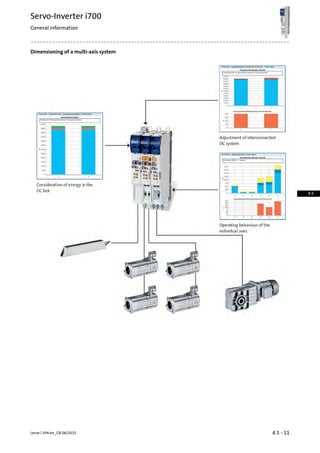
![Mains connection
Withanupstreammainschokeormainsfilter,themaximumcontinu-
ous power of the power supply modules can be used since the effect-
ive current will be reduced.
Interference voltage categories according to the European standard
EN 61800-3 are divided into category C1, C2 and the category C3.
If no filter or an RFI filter is used, the permissible continuous power
(rated power) of the power supply module is reduced.
Category C1
• Describes the use in public networks.
The mains choke and the RFI filter can also be combined without any
restrictions.Category C2
• Describes the use of devices intended for industrial purposes in
areas also comprising residential areas.
Category C3
• Describes the use of devices intended for industrial purposes only.
Mains chokes, RFI filters, Mains filters35 -The interference voltage categories achievable due
to the filter measures are shown in conjunction with
the motor cables.
26 -
Mains fuses and cable cross-sections
ƒ The mains fuse and cable cross-section specifications are for a
mains connection of 3AC 400 V or 3AC 480 V.
ƒ Class gG/gl fuses or class gRL semiconductor fuses.
ƒ The cable cross-sections apply to PVC-insulated copper cables.
ƒ Use for installation with UL-approved cables, fuses and brackets.
Mains connectionFuseCircuit breakerProduct keyMains
voltage
Rated power
Cross-section (with
mains choke)
UL1)EN 60204-1Power supply module
qIIIUACPN
[mm2][A][A][A][V][kW]
10.040C40E70ACPS☐0304S3 AC 320 ...
528
15.4
16.063C63E70ACPS☐0604S30.9
In preparation.1)
4.5 - 25Lenze | V04-en_GB-06/2015
Servo-Inverter i700
Interfaces
4.5](https://image.slidesharecdn.com/catalogue-lenzefastmotioncontrolsolutionsportfolio-160730160451/85/Catalogue-Lenze-FAST-motion-control-solutions-portfolio-187-320.jpg)
![Motor connection
The following diagrams show the possible number of axes and the
possiblesumofmotorcablelengthstoensurecompliancewithinter-
ference suppression according to category .
ƒ Number of axes (n) / sum of the motor cable length (l)
Category C2
With mains filtersWith RFI filters
5
15
20
n
100 200 300 400 500
l [m]mot
10
5
15
20
n
100 200 300 400 500
l [m]mot
10
Category C3
With mains chokesWithout external measures
5
15
20
n
100 200 300 400 500
l [m]mot
10
5
15
20
n
100 200 300 400 500
l [m]mot
10
4.5 - 27Lenze | V04-en_GB-06/2015
Servo-Inverter i700
Interfaces
4.5](https://image.slidesharecdn.com/catalogue-lenzefastmotioncontrolsolutionsportfolio-160730160451/85/Catalogue-Lenze-FAST-motion-control-solutions-portfolio-189-320.jpg)
![Connection diagrams
Servo-Inverter i700 wiring example, axis modules
[2] 24 supply for control electronics
[3] 24 V supply for digital inputs
[4] 24 V supply for motor holding brake(s)
Lenze | V04-en_GB-06/20154.5 - 28
Servo-Inverter i700
Interfaces
4.5](https://image.slidesharecdn.com/catalogue-lenzefastmotioncontrolsolutionsportfolio-160730160451/85/Catalogue-Lenze-FAST-motion-control-solutions-portfolio-190-320.jpg)
![Connection diagrams
Servo-Inverter i700 wiring example, power supply modules
[1] 24 V supply for digital inputs
[2] 24 V supply for control electronics
4.5 - 29Lenze | V04-en_GB-06/2015
Servo-Inverter i700
Interfaces
4.5](https://image.slidesharecdn.com/catalogue-lenzefastmotioncontrolsolutionsportfolio-160730160451/85/Catalogue-Lenze-FAST-motion-control-solutions-portfolio-191-320.jpg)
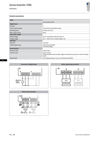
![Control connections
External 24 V supply
The control electronics of the Servo-Inverter i700 has to be supplied
with an external 24-V supply. For this purpose, Lenze provides power
supply units. The following table shows the corresponding current
consumptions of the devices.
24 V power supply unit38 -
Single axes
External DC supplyProduct keyMax. short-time output current
Current
Imax, out
[A]
1.0 A
E70ACMS☐0054SA1ET☐5.0
E70ACMS☐0104SA1ET☐10.0
E70ACMS☐0204SA1ET☐20.0
2.0 A
E70ACMS☐0324SA1ET☐32.0
E70ACMS☐0484SA1ET☐48.0
E70ACMS☐0644SA1ET☐64.0
Double axes
External DC supplyProduct keyMax. short-time output current
Current
Imax, out
[A]
1.0 A
E70ACMS☐0054SA2ET☐5.0
E70ACMS☐0104SA2ET☐10.0
2.0 A
E70ACMS☐0204SA2ET☐20.0
E70ACMS☐0324SA2ET☐32.0
4.5 - 31Lenze | V04-en_GB-06/2015
Servo-Inverter i700
Interfaces
4.5](https://image.slidesharecdn.com/catalogue-lenzefastmotioncontrolsolutionsportfolio-160730160451/85/Catalogue-Lenze-FAST-motion-control-solutions-portfolio-193-320.jpg)
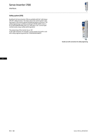
![EtherCAT® communication
EtherCAT enables the Servo-Inverter i700 to be controlled with digital
control signals via the EtherCAT® bus system. It is integrated in the
Servo-Inverter i700. It can be seen in the product key at the positions
16 and 17: E70ACM☐☐☐☐4SA☐ET☐.
The advantages of the system are:
• quick and very powerful bus system
• ideally suited for Controller-based Automation solutions
• easysystemintegrationsinceawiderangeofsensorsandactuator
is available on the market.
• the basic features of a servo drive are available in the axes according
to the device profile and can be easily used via the EtherCAT®.
FeaturesMode
Communication
EtherCAT1)
• CANopen over EtherCAT (CoE)
• Distributed clock
• 2 RJ45 connections with LEDs for link and activity
EtherCAT® is a registered trademark and patented technology, licensed by
Beckhoff Automation GmbH, Germany.
1)
Technical data
Product key
E70ACM☐☐☐☐4SAxET☐
Communication
CAT5e S/FTP according to ISO/ICE11801 (2002)Medium
CoE (CANopen over EtherCAT)Communication profile
Baud rate
100[MBit/s]b
Node
Slave
Network topology
Line (internal ring)
Number of logical process data channels
1
Process data words (PCD)
1 ... 3216 Bit
Number of bus nodes
Max. 65535
Max. cable length
100[m]lmaxbetween two nodes
Rated voltage
24.0[V]UN, DC
4.5 - 33Lenze | V04-en_GB-06/2015
Servo-Inverter i700
Interfaces
4.5](https://image.slidesharecdn.com/catalogue-lenzefastmotioncontrolsolutionsportfolio-160730160451/85/Catalogue-Lenze-FAST-motion-control-solutions-portfolio-195-320.jpg)
![Brake resistors for power supply modules
The assignment of brake resistors to the power supply modules is
shown in the following tables.
Brake resistor 27 ohms
MassDimensionsThermal capacityRated powerRated resistanceProduct key
Brake resistorPowersupplymod-
ule
mh x b x tCthPNRN
[kg][mm][KWs][kW][Ω]
1.0320 x 41 x 12230.00.20
27.0
ERBP027R200W
E70ACPS☐0304S 3.1550 x 110 x 10590.00.60ERBS027R600W
5.61020 x 110 x 1051801.20ERBS027R01K2
13.0486 x 236 x 3022851.90
12.0
ERBG012R01K9
E70ACPS☐0604S
28.0486 x 426 x 3027505.20ERBG012R05K2
Lenze | V04-en_GB-06/20154.5 - 34
Servo-Inverter i700
Accessories
4.5](https://image.slidesharecdn.com/catalogue-lenzefastmotioncontrolsolutionsportfolio-160730160451/85/Catalogue-Lenze-FAST-motion-control-solutions-portfolio-196-320.jpg)
![Mains chokes for power supply modules
A mains choke is an inductive resistor which is connected in the mains
cable of the power supply module. The use of a mains choke provides
the following advantages:
• Fewer effects on the mains:
The wave form of the mains current is a close approximation to a
sine wave.
• Reduction in the effective mains current:
Reduction of mains, cable and fuse loads
• Current balancing of power supply modules connected in parallel
Mains chokes can be used without restrictions in conjunction with
RFI filters.
Mains chokePlease note:
The use of a mains choke slightly reduces the mains voltage at the
input of the power supply module – the typical voltage drop across
the mains choke at the rated values is around 5%.
The selection of the correct mains chokes for the power supply mod-
ules depends on the number of connected axes. For this purpose,
different mains chokes are available. For the following efficiencies of
the power supply modules, we have dimensioned model mains
chokes:
• Power supply modules for 30 A operation with rated data
• Power supply modules for 60 A operation with rated data
MassDimensionsRated currentOutput powerProduct key
at 400 VMains chokePowersupplymod-
ule
mh x b x tINPout
[kg][mm][A][kW]
5.8110 x 155 x 16725.015.4EZAELN3025B122E70ACPS☐0304S
8.4112 x 185 x 20850.030.9EZAELN3050B591E70ACPS☐0604S
The following diagram shows the possible number of axes and the
possiblesumofmotorcablelengthstoensurecompliancewithinter-
ference suppression according to category C3.
Number of axes (n) / sum of the motor cable length (l)
5
15
20
n
100 200 300 400 500
l [m]mot
10
4.5 - 35Lenze | V04-en_GB-06/2015
Servo-Inverter i700
Accessories
4.5](https://image.slidesharecdn.com/catalogue-lenzefastmotioncontrolsolutionsportfolio-160730160451/85/Catalogue-Lenze-FAST-motion-control-solutions-portfolio-197-320.jpg)
![Interference suppression of power supply modules
RFI filters
RFI filters are primarily capacitive accessory components which can
beconnecteddirectlyupstreamfromthepowersupplymodules.This
measureenablescompliancewiththecorrespondingconductednoise
emission requirements according to EN 61800-3.
RFI filter, can be mounted beside
the power supply module
MassDimensionsMax. cable lengthPower lossRatedcurrentOutput
power
Product key
ReferencegroupC2at 400 VRFI filterPowersupplymod-
ule
mh x b x tlmaxPVINPout
[kg][mm][m][kW][A][kW]
4.2
485 x 60 x 2616 axes of 50 m
each
0.0208.003.60E94AZRP0084
E70ACPS☐0304S
4.50.05029.010.3E94AZRP0294
18.5490 x 209 x 2720.08082.020.6E94AZRP0824E70ACPS☐0604S
The following diagram shows the possible number of axes and the
possiblesumofmotorcablelengthstoensurecompliancewithinter-
ference suppression according to category C2.
Number of axes (n) / sum of the motor cable length (l)
5
15
20
n
100 200 300 400 500
l [m]mot
10
Lenze | V04-en_GB-06/20154.5 - 36
Servo-Inverter i700
Accessories
4.5](https://image.slidesharecdn.com/catalogue-lenzefastmotioncontrolsolutionsportfolio-160730160451/85/Catalogue-Lenze-FAST-motion-control-solutions-portfolio-198-320.jpg)
![Interference suppression of power supply modules
Mains filters
A mains filter is a combination of mains choke and RFI filter in one
housing. It reduces the conducted interference emission into the
mains in order that the conducted interference voltage is reduced to
the area permissible according EN61800-3.
This results in the following advantages:
• Fewer effects on the mains:
The wave form of the mains current is a close approximation to a
sine wave.
• Reduction in the effective mains current:
Reduction of mains, cable and fuse loads
• Current balancing when power supply modules are connected in
parallel
MassDimensionsMax. cable lengthVoltage dropRated currentOutput
power
Product key
Reference group
C2
at 400 VMains filterPowersupplymod-
ule
mh x b x tlmaxUINPout
[kg][mm][m][V][A][kW]
8.6485 x 90 x 261
10 axes of 50 m
each
10.08.004.90E94AZMP0084
E70ACPS☐0304S
16.5485 x 120 x 2617.329.015.4E94AZMP0294
29.0490 x 270 x 2726.482.030.6E94AZMP0824E70ACPS☐0604S
The following diagram shows the possible number of axes and the
possiblesumofmotorcablelengthstoensurecompliancewithinter-
ference suppression according to category C2.
Number of axes (n) / sum of the motor cable length (l)
5
15
20
n
100 200 300 400 500
l [m]mot
10
4.5 - 37Lenze | V04-en_GB-06/2015
Servo-Inverter i700
Accessories
4.5](https://image.slidesharecdn.com/catalogue-lenzefastmotioncontrolsolutionsportfolio-160730160451/85/Catalogue-Lenze-FAST-motion-control-solutions-portfolio-199-320.jpg)
![24 V power supply unit
The control electronics of the axis and power supply modules must
be supplied by external 24-V power supply units. For this purpose,
various power supply units are available. The power supply units can
be supplied with AC voltage and DC voltage from the DC bus of the
drive system. This ensures a continuous supply of the electronics in
case of mains failure to ensure a controlled braking process.
Electrical isolation
The i700 components have a save separation between mains and
electronic potential according to IEC 61131−2. For maintaining this
feature, the successive power supply units can be used with SELV
(Safety Extra Low Voltage) or PELF (Protective Extra Low Voltage).
24 V power supply unit
Product key
EZV4800-001EZV2400-001EZV1200-001EZV4800-000EZV2400-000EZV1200-000
Rated voltage
400230[V]UN, ACAC
Input voltage
AC 320 ... 575AC 85 ... 264[V]Uin
DC 450 ...800DC 90 ...350
Rated mains current
1.00.60.32.31.20.8[A]IN, AC
Output voltage
DC 22.5 ...28.5[V]Uout
Rated output current
20.010.05.020.010.05.0[A]IN, out
Dimensions
130[mm]hHeight
16085731578555[mm]bWidth
125[mm]tDepth
Mass
1.91.11.02.51.20.8[kg]m
Installation sets for Servo-Inverter i700
The installation sets include:
• All plug-in terminals
• Shield sheets plus shield terminals
• EtherCAT® cable (100 mm) for connecting the next axis
Product keyFeaturesMode
E70AZEVK001
Installation set for single axes
• For axes 5 to 20 A
E70AZEVK003• For axes 32 to 64 A
E70AZEVK002
Installation set for double axes
• For axes 5 to 10 A
E70AZEVK004• For axes 20 to 32 A
E70AZEVK005
Installation set for power supply modules
• For power supply module 30 A
E70AZEVK006• For power supply module 60 A
E70AZEVK007• For parallel connection
Lenze | V04-en_GB-06/20154.5 - 38
Servo-Inverter i700
Accessories
4.5](https://image.slidesharecdn.com/catalogue-lenzefastmotioncontrolsolutionsportfolio-160730160451/85/Catalogue-Lenze-FAST-motion-control-solutions-portfolio-200-320.jpg)


Lenze provides a comprehensive l-force product portfolio for automation systems, including various controllers, inverters, motors, and gearboxes designed for efficient machine engineering. The document outlines solutions for controller-based automation, emphasizing ease of integration and the importance of tailored support through expert engineering tools. Lenze aims to simplify machine development while ensuring high quality, reliability, and fast delivery across its global logistics network.


