1. Calculating the Max Eb/No Ratio You Can Provide with a Noisecom CNG-EbNo Unit
Introduction
Eb/No is a very important parameter for those who work with
digital communication systems. Usually this term shows up while
discussing bit error rate (BER) or modulation methods in a com-
munication system. Eb/No is defined as the ratio of Energy per Bit
(Eb) to the Spectral Noise Density (No). It is basically a signal to
noise ratio present at the input to a receiver and is used as the
basic measure of how strong the signal is. It is very important for
any Noisecom CNG-EbNo user to determine the correct Eb/No value
and also to be aware of the maximum of that value. Hence, this ap-
plication note describes how to calculate the maximum Eb/No ratio
from a Noisecom CNG-EbNo instrument.
Importance of Eb/No Parameter
It is often said that the Eb/No ratio in digital communication is
equivalent to the SNR in analog communication systems. The prob-
ability of bit error is proportional to erfc(Eb/No). As the argument
of erfc() increases, the probability of error also decreases. Thus it
is very important to have either high Eb (Energy per Bit) or low
No (Spectral Noise Density) for good quality reception. Eb is the
energy per bit for the clean signal and No is the noise PSD (Power
Spectral Density) amplitude. Hence Eb/No is of the great impor-
tance and all BER and SER (Symbol Error Rate) curves are plotted
versus Eb/No.
Eb/No Ratio Calculation
Different forms of modulation like BPSK, QPSK, QAM, etc. have
different curves of theoretical bit error rates (BER) versus Eb/No.
These curves show the communications engineer the best per-
formance that can be achieved across a digital link with a given
amount of RF power and noise level in the system.
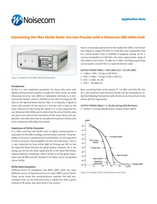
Here is an example calculation for the model CNG-EbNo-1550 which
has frequency range 950 MHz to 2150 MHz and is generally used
for L-band modem tests or Satellite IF loopback testing. So for a
receiver bandwidth of 1200 MHz, the noise output power range of
CNG-EbNo-1550 is from -55 dBm to +5 dBm. The following formula
can be used to convert this to a spectral density value
Output Power (dBm) = PSD (dBm/Hz) + 10 log (BW)
• 5 dBm = PSD + 10 log (1200 MHz)
• PSD = 5 dBm – 10 log (1200 x 106 Hz)
• PSD = 5 dBm -91 dB
• PSD = - 86 dBm/Hz
Now, assuming fixed carrier power of -10 dBm and data Bit rate
of 1, the maximum and minimum Eb/No can be calculated by us-
ing the following formula for both minimum and maximum noise
power density respectively:
Output Power (dBm) = C- Eb/No+10 log (BW/Bit Rate)
• Eb/No= C+10 log (BW/Bit Rate)- Output Power (dBm)
Figure 1: Noisecom CNG-EbNo SNR Noise Generator
Figure 2: Example of BER, Coding Scheme and Eb/No
Application Note
![What we can observe from the above example table is that the PSD
value is only related to the bandwidth and noise output power set-
ting of the instrument. The noise power spectral density is not af-
fected by the selection of carrier power or bit rate.
On the other hand, the Eb/No value is related to carrier power and
bit rate settings of the instrument. If we do not change the carrier
power but only increase the bit rate then the Eb/No also increases.
For the lower value of the carrier power, the Eb/No calculation also
decrease for the same receiver bandwidth.
Conclusion
A Noisecom CNG-EbNo series is an example of calculating maximum
Eb/No for a digital communication system. So, carrier power and
bit rate are the most important parameters which need to be con-
sidered in order to calculate the maximum Eb/No ratio for a specific
range of power spectral density, noise output power and a fixed
bandwidth.
Carrier Power
(dBm)
Bandwidth
(MHz)
Noise Power
(dBm)
Noise PSD
(dBm/Hz)
Bit
Rate
Eb
/No
-10 1200 5 (max) -86 1 76
-10 1200 -55 (min) -146 1 136
-10 1200 5 (max) -86 10 85
-10 1200 -55 (min) -146 10 145
-20 1200 5 (max) -86 1 66
-20 1200 -55 (min) -146 1 126
-20 1200 5 (max) -86 10 84
-20 1200 -55 (min) -146 10 144
References:
[1] Noisecom CNG- Eb/No Noise Generator: http://noisecom.com/
products/instruments/cng-ebno-snr-noise-generator
[2] Data sheet for CNG- Eb/No: http://noisecom.com/~/media/Noisec-
om/Datasheets/CNG_EbNo_Datasheet_PR3.ashx
[3] Webinar on Signal-to-Noise, Carrier-to-Noise and Eb/No : http://
noisecom.com/resource-library/webinars/sn-cn-ebno-webinar
Wireless Telecom Group Inc.
25 Eastmans Rd
Parsippany, NJ
United States
Tel: +1 973 386 9696
Fax: +1 973 386 9191
www.noisecom.com
© Copyright 2013
All rights reserved.
Note: Specifications, terms and conditions
are subject to change without prior notice.](data:image/gif;base64,R0lGODlhAQABAIAAAAAAAP///yH5BAEAAAAALAAAAAABAAEAAAIBRAA7)