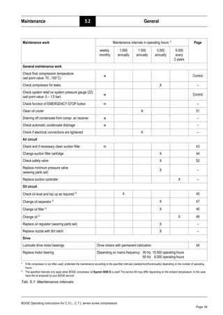
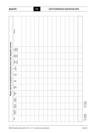
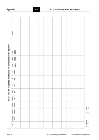
This document provides operating instructions for BOGE screw compressors models C3L through C7L. It contains information about safety, installation, operation, maintenance and repairs. The document is divided into 6 parts that cover general safety, product description, installation, troubleshooting, maintenance, and appendices. Maintenance instructions are provided for regular tasks like checking fluid levels, replacing filters, and inspecting safety valves. Replacement parts are listed.


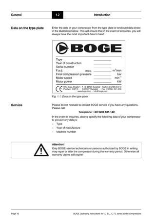
![BOGE Operating instructions for C 3 L...C 7 L series screw compressors Page 11
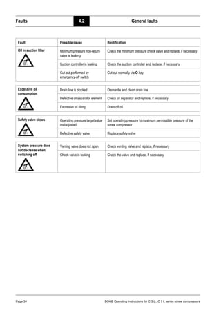
Product description 2.1 Technical data
Part 2: Product description 2.1 Technical data
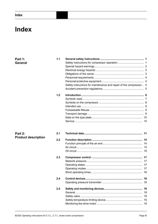
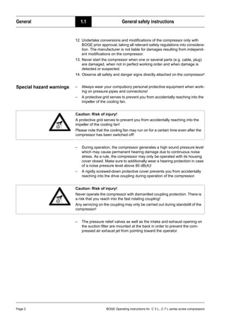
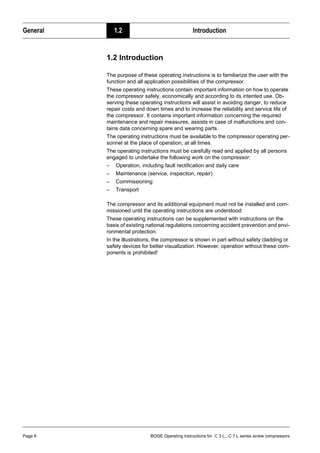
Technical data for C 3 L...C 7 L Compressor assembly, part 1
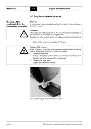
Type C 3 L C 4 L C 5 L C 7 L
Dimensions
– Width [mm] 755 755 755 755
– Depth [mm] 485 485 485 485
– Height [mm] 492 492 492 492
Weight
– silenced [kg] 105 110 125 130
– super silenced [kg] – – – –
Max. sound pressure level [±3 dB(A)]
accord. to DIN 45635, part 13
– silenced / super silenced [dB(A)] 61 62 67 68
Reference surface measure
– silenced / super silenced [dB(A)] 13 13 13 13
Sound power level
– silenced / super silenced [dB(A)] 74 75 80 81
Compressor
max. final compression temperature [°C] 110 110 110 110
Volume flow according to
ISO 1217 appendix C at:
– pmax = 8 bar [m3
/min] – – – –
– pmax = 10 bar [m3
/min] 0.240 0.340 0.545 0.728
– pmax = 13 bar [m3
/min] – 0.234 – 0.525
Drive motor
Rated power [kW] 2.2 3.0 4.0 5.5
Nominal speed
– 50 Hz [min–1
] 1500 1500 3000 3000
Protection type IP 55 55 55 55
Design IMB 35 35 35 35
ISO class F F F F
Electrical connection
Mains voltage 1)
[V]
1)
Standard equipment. Mains voltages and frequencies are specified on a plate in the switch cabinet.
230/400 400 400 400
Frequency 1)
[Hz] 50/50 50 50 50
Min. fuse protection 2) 3)
[A]
2)
Only for 400 V / 50 Hz. The fuse values change in the case of other mains voltages and frequencies.
3)
Use fuse gL – gG or circuit-breaker with C-characteristic only.
16/10 16 16 20
Recommended fuse protection 2) 3)
[A] 16/16 20 25 25](https://image.slidesharecdn.com/c3-c4-c5-c7-operating-instructions-231029124653-601f79a9/85/C3-C4-C5-C7-Operating-Instructions-pdf-19-320.jpg)
![Product description 2.1 Technical data
Page 12 BOGE Operating instructions for C 3 L...C 7 L series screw compressors
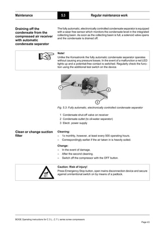
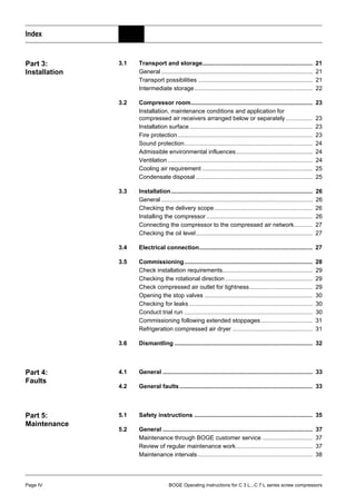
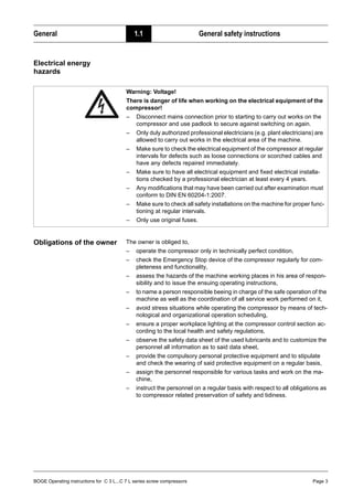
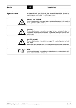
Technical data for C 3 LR...C 7 LR Compressed air system, 90-litre-receiver, 10 bar, part 1
C 3 LDR...C 7 LDR Compressed air centre, 270-litre-receiver, 10 bar, part 1
Type C 3 LR C 4 LR C 5 LR C 7 LR C 3 LDR C 4 LDR C 5 LDR C 7 LDR
Dimensions
– Width [mm] 1185 1185 1185 1185 1725 1725 1725 1725
– Depth [mm] 550 550 550 550 675 675 675 675
– Height [mm] 965 965 965 965 1165 1165 1165 1165
Receiver volume [l] 90 90 90 90 270 270 270 270
Weight
– silenced [kg] 175 180 195 200 245 250 265 270
– super silenced [kg] – – – – – – – –
Max. sound pressure level [±3 dB(A)]
accord. to DIN 45635, part 13
– silenced / super silenced [dB(A)] 61 62 67 68 61 62 67 68
Reference surface measure
– silenced / super silenced [dB(A)] 13 13 13 13 13 13 13 13
Sound power level
– silenced / super silenced [dB(A)] 74 75 80 81 74 75 80 81
Compressor
max. final compression temperature [°C] 110 110 110 110 110 110 110 110
Volume flow according to
ISO 1217 appendix C at:
– pmax = 8 bar [m3
/min] – – – – – – – –
– pmax = 10 bar [m3
/min] 0.240 0.340 0.545 0.728 0.240 0.340 0.545 0.728
– pmax = 13 bar [m3
/min] – – – – – – – –
Drive motor
Rated power [kW] 2.2 3.0 4.0 5.5 2.2 3.0 4.0 5.5
Electrical power intake dryer [kW] – – – – 0.19 0.21 0.21 0.28
Nominal speed
– 50 Hz [min–1
] 1500 1500 3000 3000 1500 1500 3000 3000
Protection type IP 55 55 55 55 55 55 55 55
Design IMB 35 35 35 35 35 35 35 35
ISO class F F F F F F F F
Electrical connection
Mains voltage compressor 1)
[V]
1)
Standard equipment. Mains voltages and frequencies are specified on a plate in the switch cabinet.
230/400 400 400 400 230/400 400 400 400
Mains voltage dryer 1)
[V] 230 – – – 230 230 230 230
Frequency 1)
[Hz] 50/50 50 50 50 50/50 50 50 50
Min. fuse protection 2) 3)
[A]
2)
Only for 400 V / 50 Hz. The fuse values change in the case of other mains voltages and frequencies.
3)
Use fuse gL – gG or circuit-breaker with C-characteristic only.
16/10 16 20 20 16/10 16 20 20
Recommended fuse protection 2) 3)
[A] 16/16 20 25 25 16/16 20 25 25](https://image.slidesharecdn.com/c3-c4-c5-c7-operating-instructions-231029124653-601f79a9/85/C3-C4-C5-C7-Operating-Instructions-pdf-20-320.jpg)
![BOGE Operating instructions for C 3 L...C 7 L series screw compressors Page 13
Product description 2.1 Technical data
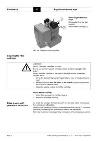
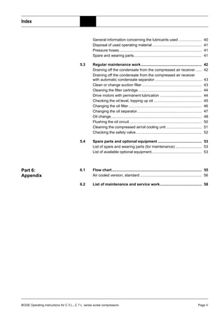
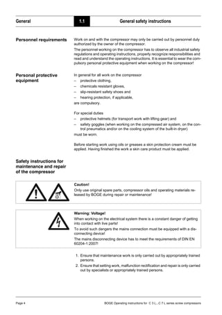
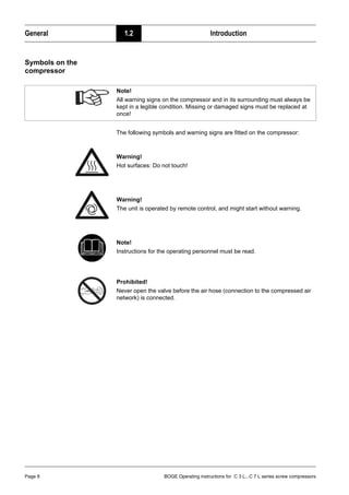
Technical data for C 4 LR, C 7 LR Compressed air system, 160-litre-receiver, 13 bar, part 1
C 4 LDR, C 7 LDR Compressed air centre, 350-litre-receiver, 13 bar, part 1
Type C 4 LR C 7 LR C 4 LDR C 7 LDR
Dimensions
– Width [mm] 1445 1445 1755 1755
– Depth [mm] 550 550 720 720
– Height [mm] 1080 1080 1215 1215
Receiver volume [l] 160 160 350 350
Weight
– silenced [kg] 230 250 300 320
– super silenced [kg] – – – –
Max. sound pressure level [±3 dB(A)]
accord. to DIN 45635, part 13
– silenced / super silenced [dB(A)] 62 68 62 68
Reference surface measure
– silenced / super silenced [dB(A)] 13 13 13 13
Sound power level
– silenced / super silenced [dB(A)] 75 81 75 81
Compressor
max. final compression temperature [°C] 110 110 110 110
Volume flow according to
ISO 1217 appendix C at:
– pmax = 8 bar [m3
/min] – – – –
– pmax = 10 bar [m3
/min] – – – –
– pmax = 13 bar [m3
/min] 0.234 0.525 0.234 0.525
Drive motor
Rated power [kW] 3.0 5.5 3.0 5.5
Electrical power intake dryer [kW] – – 0.21 0.28
Nominal speed
– 50 Hz [min–1
] 1500 3000 1500 3000
Protection type IP 55 55 55 55
Design IMB 35 35 35 35
ISO class F F F F
Electrical connection
Mains voltage compressor 1)
[V]
1)
Standard equipment. Mains voltages and frequencies are specified on a plate in the switch cabinet.
400 400 400 400
Mains voltage dryer 1)
[V] – – 230 230
Frequency 1)
[Hz] 50 50 50 50
Min. fuse protection 2) 3)
[A]
2)
Only for 400 V / 50 Hz. The fuse values change in the case of other mains voltages and frequencies.
3)
Use fuse gL – gG or circuit-breaker with C-characteristic only.
16 20 16 20
Recommended fuse protection 2) 3)
[A] 20 25 20 25](https://image.slidesharecdn.com/c3-c4-c5-c7-operating-instructions-231029124653-601f79a9/85/C3-C4-C5-C7-Operating-Instructions-pdf-21-320.jpg)
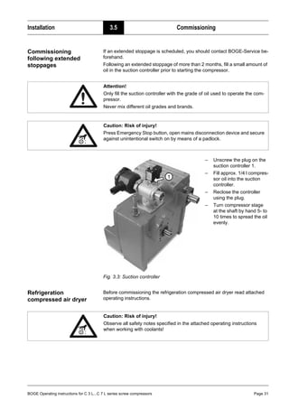
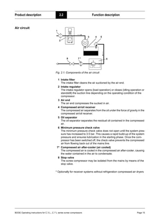
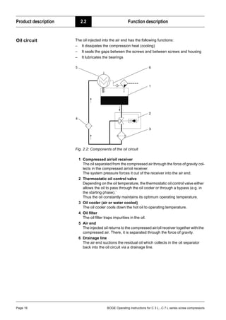
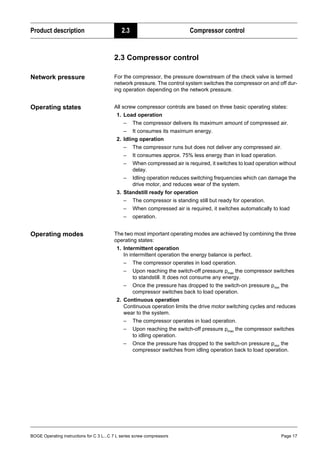
![Product description 2.2 Function description
Page 14 BOGE Operating instructions for C 3 L...C 7 L series screw compressors
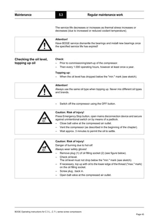
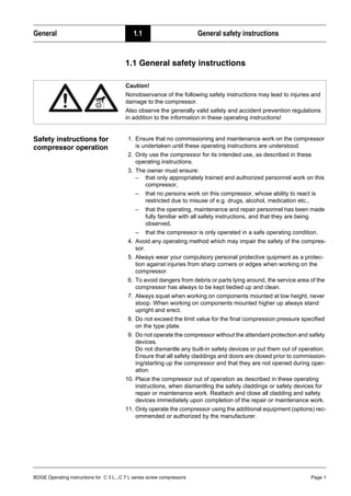
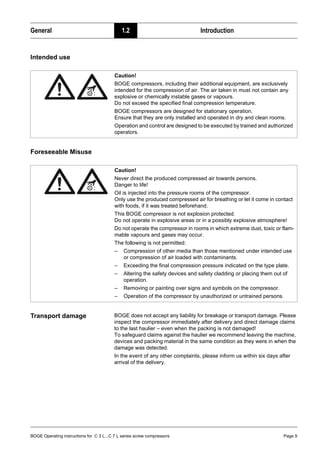
Technical data for C 3 L...C 7 L Compressor assembly / Compressed air system, part 2
C 3 LDR...C 7 LDR Compressed air centre, part 2
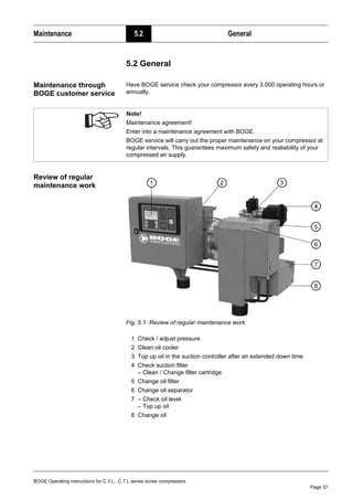
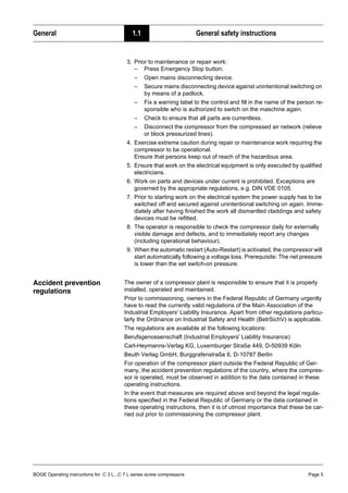
2.2 Function description
Function principle of the
air end
The air end operates according to the displacement principle. In the housing,
the main and secondary screws are driven by means of an electric motor.
Both screws have screw-shaped profiles, intermeshing without contact. To-
gether with the housing wall, these screws form chambers which gradually re-
duce in size, seen in air flow direction.
Rotation of the rotors causes the air taken in to be compressed to the final
pressure in the chambers.
During compression oil is continuously injected into the air end. This having a
cooling, sealing and lubricating function.
Type
C 3 L
C 3 LR
C 3 LDR
C 4 L
C 4 LR
C 4 LDR
C 5 L
C 5 LR
C 5 LDR
C 7 L
C 7 LR
C 7 LDR
Oil filling quantity
Total oil filling quantity [l] 4 4 4 4
Oil topping up quantity
between min. + max. [l] 1 1 1 1
Intake air temperature
– min. [°C] 5 5 5 5
– max. [°C] 40 40 40 40
Cooling air requirement
– free-standing installation [m3
/h] 800 1200 1600 2000
– with supply and exhaust [m3
/h] – – – –
– free ventilator pressure [Pa] – – – –
– free ventilator pressure [mm WC] – – – –
Operating pressure values 1)
1)
Compressors for other operating pressures Pmin = Pmax –1 bar.
(factory settings)
– pmax = 8bar: Switch-off press. pmax [bar] – – – –
Switch-on press. pmin [bar] – – – –
– pmax = 10bar: Switch-off press. pmax [bar] 10 10 10 10
Switch-on press. pmin [bar] 9 9 9 9
– pmax = 13bar: Switch-off press. pmax [bar] – 13 – 13
Switch-on press. pmin [bar] – 12 – 12
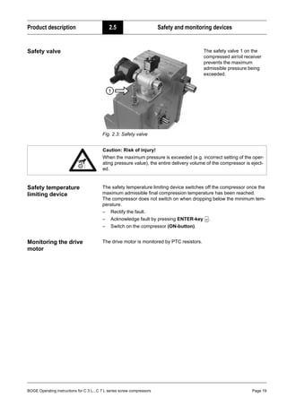
Safety valve
Activation pressure at:
– pmax = 8 bar [bar] 11 11 11 11
– pmax = 10 bar [bar] 11 11 11 11
– pmax = 13 bar [bar] 14 14 14 14](https://image.slidesharecdn.com/c3-c4-c5-c7-operating-instructions-231029124653-601f79a9/85/C3-C4-C5-C7-Operating-Instructions-pdf-22-320.jpg)

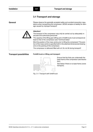
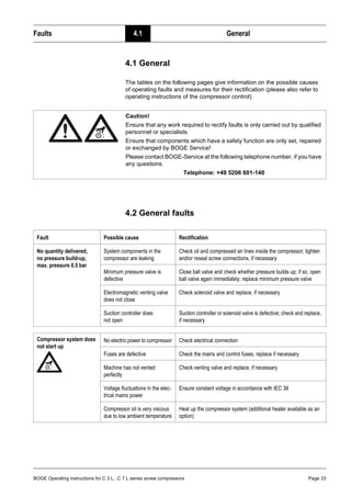
![BOGE Operating instructions for C 3 L...C 7 L series screw compressors Page 25
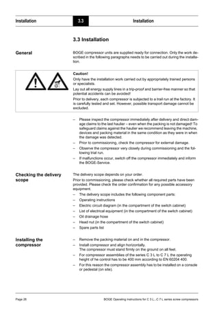
Installation 3.2 Compressor room
Ventilators
Ensure that the heated exhaust air is not taken in again.
If necessary, the heated air must be extracted by ventilators.
To ensure perfect cooling even at higher temperatures in the summer, the ven-
tilators must be designed as follows:
– The ventilator capacity must be rated approx. 10 – 15% higher than the
sum of the cooling air quantity required for all machines operated in the
room (VDMA Code of Practice sheet 4363 "Ventilation of compressor
rooms").
– For a free-standing installation, the cooling air requirement specified in the
table corresponds to the required ventilator capacity.
Cooling air requirement Please refer to the following table for the cooling air requirement and size of
the supply air openings for your compressor. Ensure that flaps and weather
protection grids have the necessary free cross section. We generally recom-
mend contacting a specialist company for performing the duct construction
work and planning.
* For the cooling air requirements the basis is a 4°C temperature difference between room and outside temperature
Tab. 3.1: Cooling air requirement, necessary aperture dimensions
Condensate disposal The air taken in contains water in form of vapour, which turns into condensa-
tion during compression.
Type Drive rating * Cooling air
requirement
for free
standing unit
Necessary inlet
opening
for free
standing unit
[kW] [m3
/h] [m2
]
C 3 L / C 3 LR / C 3 LDR
C 4 L / C 4 LR / C 4 LDR
C 5 L / C 5 LR / C 5 LDR
C 7 L / C 7 LR / C 7 LDR
2.2
3.0
4.0
5.5
800
1200
1600
2000
0.10
0.20
0.20
0.25
Attention!
The condensate contains oil. Never lead it into the public sewage system
without prior treatment.
Strictly observe the effluent disposal laws of your local authorities.
Oil-water separator
The BOGE-oil-water-separator separates the oil from the condensate.
The cleaned water may be fed directly into the public sewage system.
The oil is collected in a separate container. Dispose of the oil according to
environmental regulations.
If, due to special operating conditions, the oil should emulsify, use an emul-
sion cracking plant.](https://image.slidesharecdn.com/c3-c4-c5-c7-operating-instructions-231029124653-601f79a9/85/C3-C4-C5-C7-Operating-Instructions-pdf-33-320.jpg)