Download to read offline

![Page 14
Only two of the three ports may be activated at a time. By default, the V-Prox
shall be configured for Port Mode 1 (Host RS-485 DB15 / Aux RS-232 RJ11), which
activates the RS-485 port accessible from the pigtail and the RS-232 port
accessible from the bottom RJ11 port.
7.1. RS-485 DB15 Port
The V-Prox reader shall support RS-485 serial communications protocol
accessible from the DB15 port. This shall be the default configuration for the
reader. For RS-485 protocol support, an external converter must be utilized.
Bioscrypt has tested and qualified the B&B Electronics 485TBLED RS-485/RS-232
converter for use with the V-Prox reader (must be purchased separately). The
B&B Electronics converter connects directly to both the Host PC and to the V-
Prox reader. This converter shall support “sense data,” also referred to as
“send data”. This is necessary since the V-Prox reader shall utilize a half-duplex
(2-wire) RS-485 signal with no RTS/CTS control on the RS-232 line.
The RS-485 communications protocol should be chosen if a network of more
than one V-Prox reader is being installed or if a single reader is being installed
more than 150 feet from the PC or other host. The maximum cable distance
for a RS-485 network is 4,000 feet (1200 meters), over which no more than 31
V-Prox readers can be added. To extend these limitations, contact Bioscrypt
Technical Support. No end-of-line termination is required at a baud rate of
9600. For RS-485 communications, the V-Prox readers must be connected as
follows:
Use Category 5 rated cable (shielded is recommended). This cable
should be dedicated to the RS-485 network connection between the
B&B Electronics 485TBLED converter and the V-Prox readers and should
not be used for any other purpose.
Use Pin 7 [RS-485 (-)], Pin 8 [RS-485 (+)] and Pin 12 [Signal GND].
The B&B Electronics 485TBLED converter shall require 12VDC/100mA
power from an external supply.
Connect the B&B Electronics 485TBLED converter to the PC’s DB9 COM
Port using a DB25-to-DB9 cable.
Connect the V-Prox readers in a daisy-chain configuration (i.e.
Converter → Reader 1 → Reader 2 → Reader 3, etc.). Do NOT use a
star or other multi-drop configurations.
For a wiring diagram and more specific instructions please refer to the
Configuration for Veri-Series Fingerprint Readers and RS-485/RS-232 Converter
application note.
Document# 430-00136-04 © Copyright 2003-2006, Bioscrypt Inc. All rights reserved.](https://image.slidesharecdn.com/vproxaespecification1-130211131648-phpapp02/85/BIOSCRYPT-V-PROX-14-320.jpg)
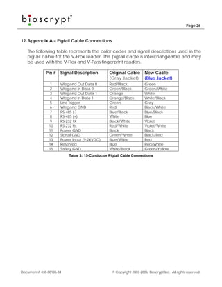

The document provides specifications for the V-Prox fingerprint reader manufactured by Bioscrypt, including: - It uses fingerprint verification and prevents access with loaned/stolen cards. - It has dimensions of 5.32" x 2.75" x 2.52" and is made of flame retardant ABS plastic. - It incorporates the Authentec AF-S2 fingerprint sensor and has been tested to comply with various certifications.


