This document provides information about the fundamentals of biochemical engineering course including:
1. The syllabus covers topics like microbiology, fermentation processes, transport phenomena, downstream processing, and effluent treatment.
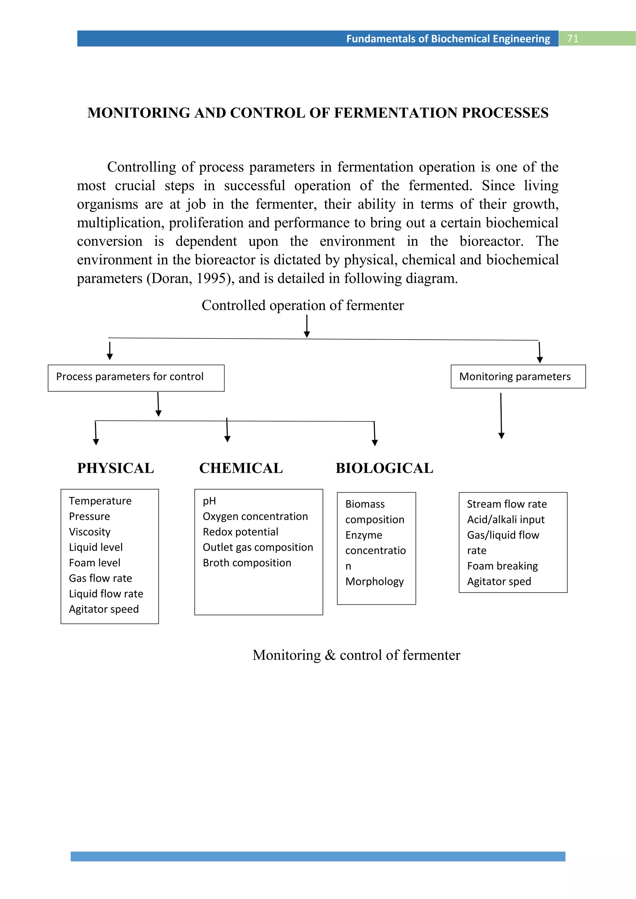
2. The lesson plan outlines classes on microbial growth kinetics, enzymes, immobilization, heat and mass transfer, monitoring fermentation processes, and recovery of products.
3. Applications of microbiology include food production, industrial product production, genetic engineering, environmental roles, and medical uses. Microbes are important in areas like dairy, agriculture, and biotechnology.


![38Fundamentals of Biochemical Engineering
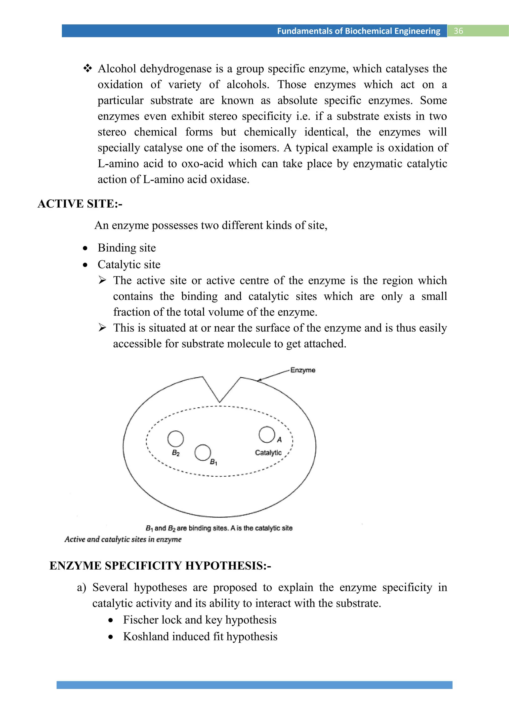
ENZYME KINETICS
The Michaelis-Menten equation is an important equation in biochemistry
and as such it is imperative that you understand the derivation of this equation.
By understanding the derivation, you will have insight into the assumptions that
went into this model, and therefore you will have a better appreciation for the
proper use of this equation as well as the limitations of this model. In the
following sections you will see two different derivations of the Michaelis-
Menten equation. When one is learning a subject for the first time, it often helps
to have the same or similar information presented from alternative perspectives.
One way might be clearer to you whereas the other way might be clearer to
someone else. That is ok! You should familiarize yourself with both
approaches, and then settle on the one that you prefer.
First Derivation. We start with the kinetic mechanism shown in equation
(eq) 1:
----------------1
In eq 1, E is enzyme, S is substrate, ES is the enzyme-substrate complex, and P
is product. This equation includes the assumption that during the early stages of
the reaction so little product is formed that the reverse reaction (product
combining with enzyme and re-forming substrate) can be ignored (hence the
unidirectional arrow under k3). Another assumption is that the concentration of
substrate is much greater than that of total enzyme ([S] >> [Et]), so it can
essentially be treated as a constant.](https://image.slidesharecdn.com/biochemicalenggnotes-180215044930/75/Bio-chemical-engg-notes-43-2048.jpg)
![39Fundamentals of Biochemical Engineering
From General Chemistry we can equate the rate of this process (k3[ES]) to the
change in product concentration as a function of time (d[P]/dt), or, equivalently,
we can designate the rate with an italicized v (v) as follows in eq 2:
-----------------------------------------------------------2
Because the concentration of the enzyme•substrate complex ([ES]) cannot be
measured experimentally, we need an alternative expression for this term.
Because the enzyme that we add to the reaction will either be unbound (E) or
bound (ES) we can express the fraction of bound enzyme as follows in eq 3 :
---------------------------------------------------------3
In eq 3 Et is the concentration of total enzyme, and the other variables are as
definedabove. If we multiply both sides of eq 3 by Et we arrive at eq 4:
-----------------------------------------------------4
If we multiply the numerator and denominator of the right-hand side of eq 4 by
1/[ES], we are, in effect, multiplying by one and we do not change the value of
this expression. When we do this we obtain eq 5:
-------------------------------------------------------5
We have almost achieved our goal of isolating [ES]. Next, we need to come up
with an alternative expression for the ratio [E]/[ES]. We do this by recalling that
a major assumption in enzyme kinetics is the steady-state assumption. Basically,
it says the rate of change of [ES] as a function of time is zero: d[ES]/dt = 0.
Another way to express the steady-state assumption is that the rate of formation
of ES equals the rate of breakdown of ES. We can express this latter statement
mathematically as in eq 6:
------------------------------------------6
The left-hand side of eq 6 expresses the rate of formation of ES (according to eq
1), and the right-hand side expresses the two ways that ES can break down (also
according to eq1). We can rearrange eq 6 to isolate the ratio [E]/[ES]. When we
do we get eq 7:](https://image.slidesharecdn.com/biochemicalenggnotes-180215044930/75/Bio-chemical-engg-notes-44-2048.jpg)
![40Fundamentals of Biochemical Engineering
----------------------------------------------------------7
We now define a new constant, the Michaelis constant (Km), as follows in eq 8:
-------------------------------------------------------8
If we substitute Km back into eq 7 we obtain eq 9:
----------------------------------------------------------9
We now substitute the ratio Km/[S] from eq 9 in place of the ratio [E]/[ES] in eq
5 and we obtain eq 10:
----------------------------------------------------10
If we multiply the numerator and denominator of the right-hand side of eq 10 by
[S], we are, in effect, multiplying by one and we do not change the value of this
expression. When we do this we obtain eq 11:
----------------------------------------11
Now we have achieved our goal of isolating [ES] and we can substitute this
alternative expression of [ES] into eq 2 and obtain eq 12:
----------------------------------12
Next, we imagine what happens to eq 12 when [S] > > Km as follows in eq 13:
--------------------13
The constant kcat in the right-hand most term of eq 13 is used to signify that k3
is considered the catalytic constant. Under such conditions, when [S] is said to](https://image.slidesharecdn.com/biochemicalenggnotes-180215044930/75/Bio-chemical-engg-notes-45-2048.jpg)
![41Fundamentals of Biochemical Engineering
be saturating, the enzyme is functioning as fast as it can and we define k3[Et] (or
kcat[Et]) to be equal to Vmax, the maximum velocity that can be obtained.
Therefore, eq 12 can be rewritten into the familiar form of the Michaelis-
Menten equation (eq 14):
----------------------------------14
Next, we imagine what happens when Km > > [S] as follows in eq 15:
--------------------------------------------15
Since k = Vmax/ Km in eq 15, we refer to Vmax/ Km as an apparent (or pseudo)
first order rate constant. Another way to look at a similar, related concept is to
rewrite eq 14 as follows:
---------------------------------16
Since we are imagining the case where Km > > [S] we neglect [S] in the
denominator and include the assumption that [Et] [E] since at very low [S]
relatively little [ES] should form:
-------------------------------------------------------17
Once again, since k’’ = kcat/Km in eq 17, we refer to kcat/Km as an apparent second
order rate constant. Because kcat/Km is a measure of the rate of the reaction
divided by the term that reflects the steady-state affinity of the enzyme for the
substrate, it is considered an indicator of the catalytic efficiency of the enzyme
and sometimes is called the specificity constant. It also is more relevant to the
physiological situation because in cells, [S] generally is equal to or less than
Km. Is there an upper limit to the value that kcat/Km can approach? Yes, there is
and the following shows how we can determine this limit. To illustrate this limit
we first need to rewrite kcat/Km as follows:
-------------------------------------------------------18
Next, we imagine the case where k3 >> k2:](https://image.slidesharecdn.com/biochemicalenggnotes-180215044930/75/Bio-chemical-engg-notes-46-2048.jpg)
![42Fundamentals of Biochemical Engineering
--------------------------------------------19
So we see that kcat/Km can approach k1 as a limiting value, and k1 is the second-
order rate constant for the productive collision of enzyme and substrate and as
such it is limited by diffusion to about 108
to 109
M-1 s-1. Thus, if we see an
enzyme that has a kcat/Km value in the neighborhood of 108
to109
M-1 s-1we say
that the enzyme has attained “catalytic perfection”. You will see later in the
class that a number of enzymes that catalyze “nearequilibrium” reactions in
metabolic pathways are catalytically perfect. Next, we return to eq 16 and
consider what happens when v = ½ Vmax
Next, we return to eq 16 and consider what happens when v = ½ Vmax:
-------------------------------------20
When we simplify eq 20 we find that Km = [S] (under the above conditions; i.e.,
v = ½Vmax). So, in other words, Km is formally defined as a collection of rate
constants (eq. 8), but it is also equal to the substrate concentration that gives
half-maximal velocity of the enzyme-catalysed reaction.
Before we discuss the second derivation, we will consider what happens when
we take the reciprocal of both sides of eq 14. When we do this we obtain eq 21:
----------------------------------------------21
Eq 21 is in the form of an equation for a straight line (i.e., y = mx + b, with y =
1/v; m =
𝐾𝑚
𝑉𝑚𝑎𝑥
; x =
1
[𝑆]
; and b =
1
𝑉𝑚𝑎𝑥
). When experimental data are plotted using
this transformation the resulting plots are called double-reciprocal plots or
Lineweaver-Burk plots in honor of the researchers who pioneered this method.
The authors of many textbooks extol the virtues of using Lineweaver-Burk
plots to obtain estimates of Vmax and Km. I disagree strongly with this practice
because initial velocity data determined at low substrate concentrations (where
there is inherently more uncertainty since [S] Km) end up being the points in
a Lineweaver-Burk plot that have too much sway in determining the best-fit line
through the data.](https://image.slidesharecdn.com/biochemicalenggnotes-180215044930/75/Bio-chemical-engg-notes-47-2048.jpg)


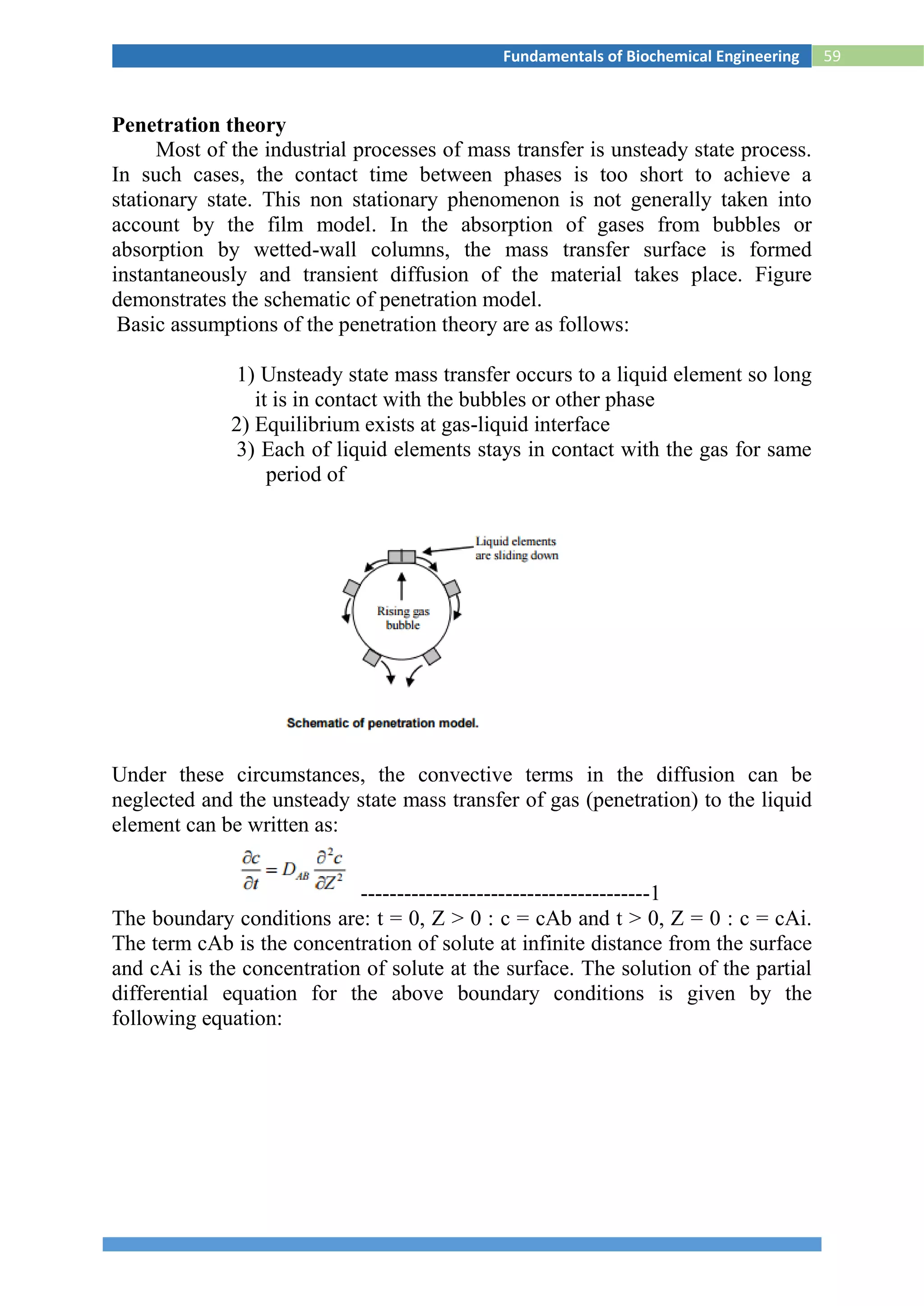

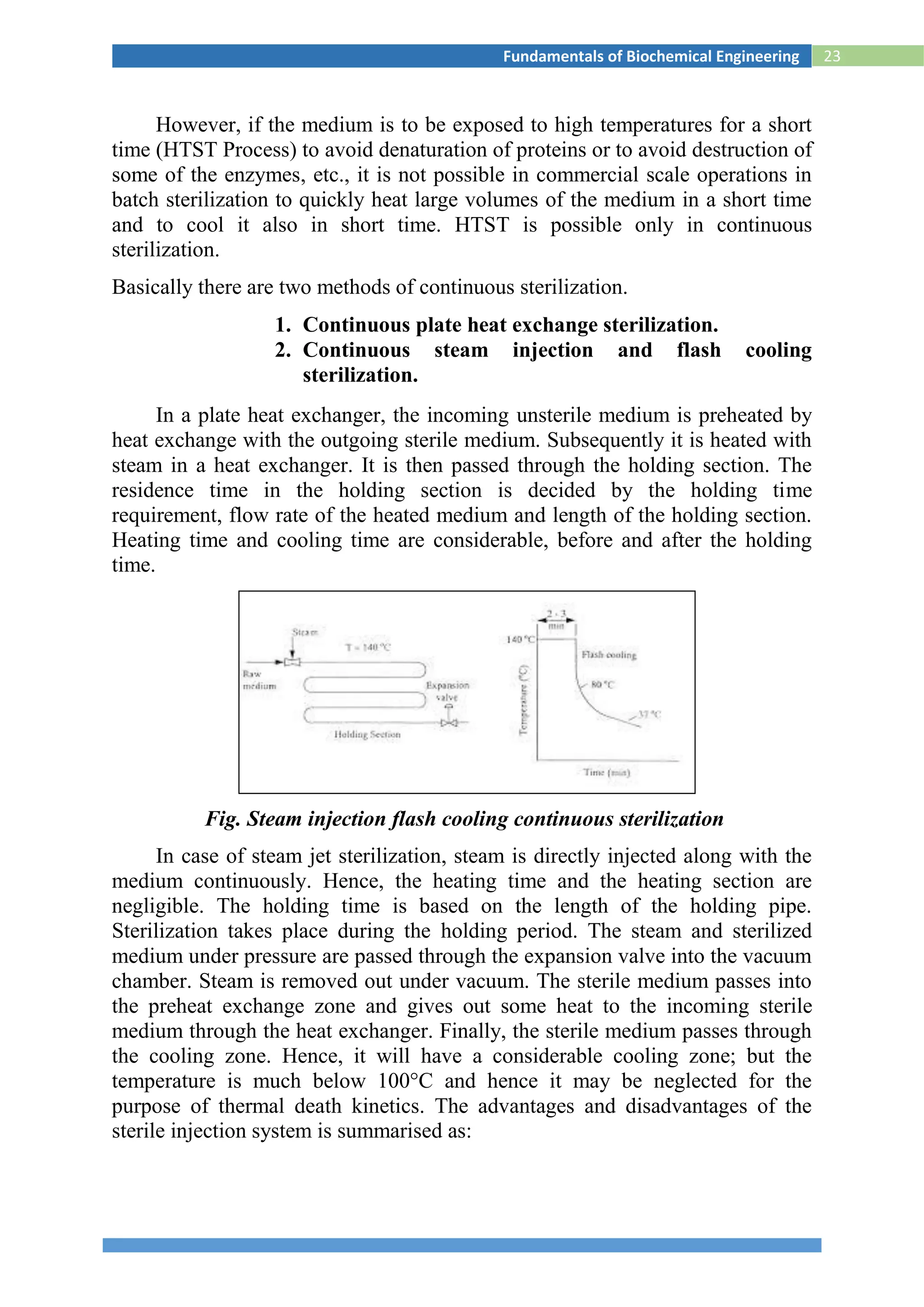
![61Fundamentals of Biochemical Engineering
Surface Renewal Theory
For the mass transfer in liquid phase, Danckwert (1951) modified the Higbie’s
penetration theory. He stated that a portion of the mass transfer surface is
replaced with a new surface by the motion of eddies near the surface and
proposed the following assumptions:
1) The liquid elements at the interface are being randomly
swapped by fresh elements from bulk
2) At any moment, each of the liquid elements at the surface has
the same probability of being substituted by fresh element
3) Unsteady state mass transfer takes place to an element during its
stay at the interface.
Hence, average molar flux, NA,av
------------------------------------7
Comparing the equations
--------------------8
where s is fraction of the surface renewed in unit time, i.e., the rate of surface
renewal [s-1].](https://image.slidesharecdn.com/biochemicalenggnotes-180215044930/75/Bio-chemical-engg-notes-66-2048.jpg)


![88Fundamentals of Biochemical Engineering
Fig.S2 Settling of solids in a batch sedimentation process
The design equations are arrived at to find the minimum area of a
continuous thickener or sedimentation tank, so that the solids (or the
sludge) are withdrawn from the bottom continuously and the clear liquid
can be decanted from the top. For a continuous thickener, the rate of
sedimentation can be equated to the counter-flow velocity of the rising
fluid (Earle, 1996).
uu = [(F - L) rs ]/ Aρf --------------------------------------iii
Where uu is the upward velocity of flow of liquid, which is also equal to
the settling velocity of the particle (ut); F is the ratio of liquid to the solids
in the feed and L is that in that in the exit stream; and rs is the mass feed
rate of the slurry.
Equation (iii) is obtained by simple mass balance. It can be used to
calculate the minimum area (A) of the sedimentation tank (or thickener).
A = [(F - L) rs] / ut ρf ----------------------------iv
The above equation can be used to evaluate the minimum cross-sectional
area of the thickener, provided we know the average particle size dp,
which is the major drawback. The sedimentation slurry may not have all
particles of same diameter, In which case, we may have to find out the
mean particle size by averaging out various particle sizes and their mass
fractions, which is also a difficult task. Mostly, the sedimentation
operations are highly time-consuming. It takes a lot of time for the solids
to settle.](https://image.slidesharecdn.com/biochemicalenggnotes-180215044930/75/Bio-chemical-engg-notes-93-2048.jpg)


![118Fundamentals of Biochemical Engineering
3. (a)
(b)
What are the various parameters that can be control for the successful
operation of a fermentor?
Briefly explain what are factors affecting oxygen transfer rate in
fermentation process.
06
04
4. Explain in details the production of biogas and what are the factors
affecting methane formation.
10
5. The following data have been obtained for two different initial enzyme
concentrations for an enzyme-catalyzed reaction.
v([E0]=0.015g/l)
(g/l-min)
1.1
4
0.8
7
0.70 0.59 0.50 0.44 0.39 0.35
[S]
(g/l)
20.
0
10.
0
6.7 5.0 4.0 3.3 2.9 2.5
v([E0]=0.00875g/l)
(g/l-min)
0.6
7
0.5
1
0.41 0.34 0.29
i)Find Km](https://image.slidesharecdn.com/biochemicalenggnotes-180215044930/75/Bio-chemical-engg-notes-123-2048.jpg)
![119Fundamentals of Biochemical Engineering
ii)Find Vm for [E0]=0.015 g/l and [E0]=0.00875 g/l
iii)Find K2 10
6. (a)
(b)
What are the general requirements of a fermentation process?
Explain in details the design and construction of a fermentor.
03
07
7. (a) Briefly explain the enzyme specificity hypothesis. 05
(b) Explain different methods of air sterilization.
05
8. Write short notes on any TWO: 5 x 2
(a) Tubular bowl cenrtifuge
(b) Trickling filter
(c) vaccines
(d) Chromatography](https://image.slidesharecdn.com/biochemicalenggnotes-180215044930/75/Bio-chemical-engg-notes-124-2048.jpg)


![Seller Deck - Presentation [Concert L2].PPTX](https://cdn.slidesharecdn.com/ss_thumbnails/sellerdeck-presentationconcertl2-251219171156-24982daf-thumbnail.jpg?width=640&height=640&fit=bounds)


