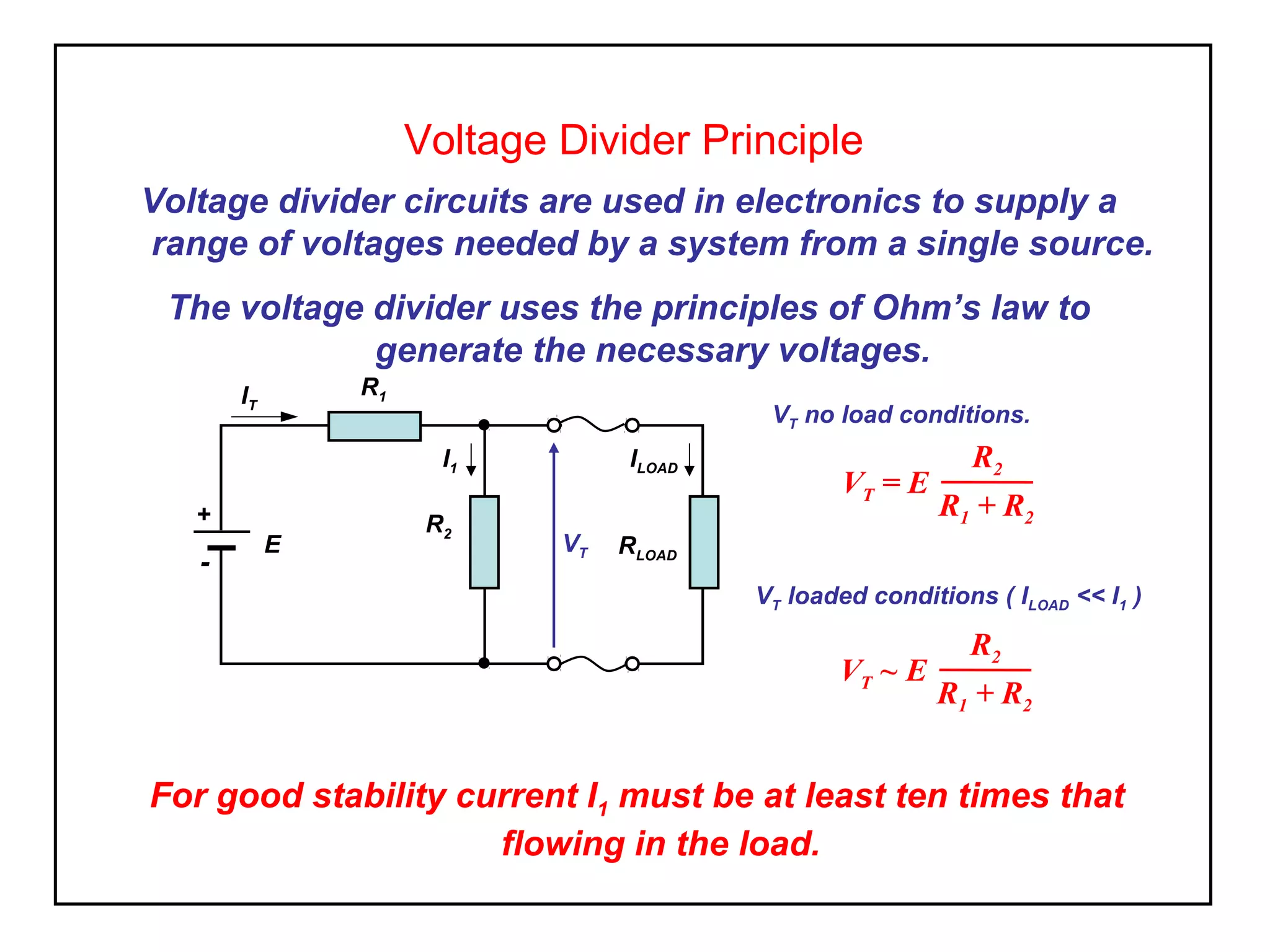
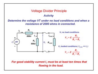
Voltage Divider Principle
Voltage divider circuits are used in electronics to supply a
range of voltages needed by a system from a single source.
The voltage divider uses the principles of Ohm’s law to
generate the necessary voltages.
VT = E
R2
R1 + R2
For good stability current I1 must be at least ten times that
flowing in the load.
IT
RLOAD
ILOADI1
R1
R2
VTE
+
-
VT no load conditions.
VT ~ E
R2
R1 + R2
VT loaded conditions ( ILOAD << I1 )
Voltage Divider Principle
Activity
Determine the voltage VT under no load conditions and when a
resistance of 2000 ohms in connected.
VT = E
R2
R1 + R2
For good stability current I1 must be at least ten times that
flowing in the load.
VT no load conditions.
VT ~ E
R2
R1 + R2
VT loaded conditions ( ILOAD << I1 )
IT
RLOAD
ILOADI1
R1
R2
VT
+
-
20VE
500Ω
500Ω
Divider Networks
Activity
1. For the potential divider circuit shown, use the voltage divider principle to
evaluate the voltage at VT a) when open circuit and b) when a load of 1000Ω
is connected as shown.
2. If the load resistance (RLOAD ) increased to 5kΩ what will be the effect on the
voltage VT .
3. Comment on your results
What is the effect on the voltage (VT ) supplied by the potential divider network
as the load (RLOAD )varies.
IT
RLOAD
ILOADI1
R1
450Ω
R2
300Ω
VT
+
-
25VE

Elect principles 2 voltage divider

  • 1.
    Voltage Divider Principle Voltagedivider circuits are used in electronics to supply a range of voltages needed by a system from a single source. The voltage divider uses the principles of Ohm’s law to generate the necessary voltages. VT = E R2 R1 + R2 For good stability current I1 must be at least ten times that flowing in the load. IT RLOAD ILOADI1 R1 R2 VTE + - VT no load conditions. VT ~ E R2 R1 + R2 VT loaded conditions ( ILOAD << I1 )
  • 2.
    Voltage Divider Principle Activity Determinethe voltage VT under no load conditions and when a resistance of 2000 ohms in connected. VT = E R2 R1 + R2 For good stability current I1 must be at least ten times that flowing in the load. VT no load conditions. VT ~ E R2 R1 + R2 VT loaded conditions ( ILOAD << I1 ) IT RLOAD ILOADI1 R1 R2 VT + - 20VE 500Ω 500Ω
  • 3.
    Divider Networks Activity 1. Forthe potential divider circuit shown, use the voltage divider principle to evaluate the voltage at VT a) when open circuit and b) when a load of 1000Ω is connected as shown. 2. If the load resistance (RLOAD ) increased to 5kΩ what will be the effect on the voltage VT . 3. Comment on your results What is the effect on the voltage (VT ) supplied by the potential divider network as the load (RLOAD )varies. IT RLOAD ILOADI1 R1 450Ω R2 300Ω VT + - 25VE