Audible visible notification
•
0 likes•410 views

This document provides specifications for SpectrAlert Advance outdoor horns, strobes, and horn strobes for wall applications. It summarizes their key features as having weatherproof housings, field-selectable settings for candela, voltage, tones and volume. They are designed for both indoor and outdoor use in temperatures from -40°F to 151°F. The document also lists the products' agency listings, specifications including dimensions and wiring, ordering information and diagrams.

Recommended
More Related Content
What's hot
Similar to Audible visible notification
Similar to Audible visible notification (20)
More from sanzen enterprises
More from sanzen enterprises (20)
Audible visible notification
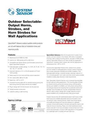
- 1. Outdoor Selectable- Output Horns, Strobes, and Horn Strobes for Wall Applications SpectrAlert® Advance outdoor audible visible products are rich with features that cut installation times and maximize profits. Features SpectrAlert Advance offers the broadest line of outdoor horns, strobes, and horn strobes in the industry. With white or red plastic • Weatherproof per NEMA 4X, IP56 housings, wall or ceiling mounting options, and plain or FIRE-printed • isted to UL 1638 (strobe) and UL 464 (horn) L devices, SpectrAlert Advance can meet virtually any application • ompatible with System Sensor synchronization protocol and C requirement, including indoor, outdoor, wet, and dry applications in legacy SpectrAlert products temperatures from −40°F to 151°F. • ield-selectable candela settings: 15, 15/75, 30, 75, 95, 110, 115, F Like the entire SpectrAlert Advance line, outdoor horns, strobes, 135, 150, 177, and 185 and horn strobes for wall applications include a variety of features • utomatic selection of 12- or 24-volt operation at 15 and A that increase application flexibility and simplify installation. First, 15/75 candela field-selectable settings, including candela, automatic selection of • Rotary switch for horn tone and three volume selections 12- or 24-volt operation, horn tones, and three volume options enable installers to easily adapt devices to meet requirements. • Horn rated at 88+ dBA at 16 volts • Rated from –40°F to 151°F Next, SpectrAlert Advance devices use a universal mounting plate • niversal mounting plate with an onboard shorting spring that U for both wall and ceiling applications. This mounting plate includes tests wiring continuity before devices are installed an onboard shorting spring that ensures wiring continuity before devices are installed, so installers can verify proper wiring without • Plug-in design with minimal intrusion into the back box mounting the devices and exposing them to potential construction • Tamper-resistant construction damage. Once the plates are mounted, all SpectrAlert Advance • Listed for ceiling or wall mounting devices utilize a plug-in design with a single captured screw to speed installation and virtually eliminate costly ground faults. Outdoor devices ship with weatherproof plastic back boxes (metal back boxes are available separately) that accommodate in-and- Agency Listings out wiring for daisy chaining devices. Plastic back boxes feature removable side flanges and improved resistance to saltwater corrosion. Knock-outs located on the back eliminate the need to drill holes for screw-in mounting. Plastic and metal weatherproof back boxes come with ¾‑inch top and bottom conduit entries and ¾‑inch 7300-1653:187 (outdoor strobes) 7125-1653:188 horn strobes, ( knock-outs at the back. A screw-in NPT plug with an O-ring gasket S4011 (chimes, horn strobes, horns) chime strobes) S3593 (outdoor and alert strobes) 3023572 MEA452-05-E 7135-1653:189 (horns, chimes) for a watertight seal is included with each back box.
- 2. SpectrAlert Advance Outdoor Horn, Strobe, and Horn Strobe Specifications Architect/Engineer Specifications General SpectrAlert Advance outdoor horns, strobes, and horn strobes shall mount to a weatherproof back box. A universal mounting plate shall be used for mounting ceiling and wall products. The notification appliance circuit wiring shall terminate at the universal mounting plate. Also, SpectrAlert Advance products, when used with the Sync•Circuit™ Module accessory, shall be powered from a non-coded notification appliance circuit output and shall operate on a nominal 12 or 24 volts. When used with the Sync•Circuit Module, 12-volt-rated notification appliance circuit outputs shall operate between 9 and 17.5 volts; 24-volt-rated notification appliance circuit outputs shall operate between 17 and 33 volts. Outdoor SpectrAlert Advance products shall operate between −40 and 151 degrees Fahrenheit from a regulated DC or full-wave rectified unfiltered power supply. Strobes and horn strobes shall have field-selectable candela settings including 15, 15/75, 30, 75, 95, 110, 115, 135, 150, 177, and 185. Strobe The strobe shall be a System Sensor SpectrAlert Advance Model _______ listed to UL 1971 and shall be approved for fire protective service. The strobe shall be wired as a primary-signaling notification appliance and comply with the Americans with Disabilities Act requirements for visible signaling appliances, flashing at 1 Hz over the strobe’s entire operating voltage range. The strobe light shall consist of a xenon flash tube and associated lens/reflector system. The strobe must be installed with its weatherproof back box in order to remain outdoor approved per UL. The strobe shall be suitable for use in wet environments. Horn Strobe Combination The horn strobe shall be a System Sensor SpectrAlert Advance Model _______ listed to UL 1971 and UL 464 and shall be approved for fire protective service. The horn strobe shall be wired as a primary-signaling notification appliance and comply with the Americans with Disabilities Act requirements for visible signaling appliances, flashing at 1 Hz over the strobe’s entire operating voltage range. The strobe light shall consist of a xenon flash tube and associated lens/reflector system. The horn shall have three audibility options and an option to switch between a temporal three pattern and a non-temporal (continuous) pattern. These options shall be set by a multiple position switch. On four-wire products, the strobe shall be powered independently of the sounder. The horn or horn strobe models shall operate on a coded or non-coded power supply. The horn strobe must be installed with its weatherproof back box in order to remain outdoor approved per UL. The horn strobe shall be suitable for use in wet environments. Physical/Electrical Specifications Operating Temperature –40°F to 151°F (–40°C to 66°C) Strobe Flash Rate 1 flash per second Nominal Voltage Regulated 12 DC/FWR or regulated 24 DC/FWR1 Operating Voltage Range2 8 to 17.5 V (12 V nominal) or 16 to 33 V (24 V nominal) Input Terminal Wire Gauge 12 to 18 AWG Wall-Mount Dimensions (including lens) 5.6˝ L × 4.7˝ W × 2.5˝ D (142 mm L × 119 mm W × 64 mm D) Horn Dimensions 5.6˝ L × 4.7˝ W × 1.3˝ D (142 mm L × 119 mm W × 33 mm D) Wall-Mount Weatherproof Back Box Dimensions (SA-WBB) 5.7˝ L × 5.1˝ W × 2.0˝ D (145 mm L × 130 mm W × 51 mm D) Notes: 1. Full Wave Rectified (FWR) voltage is a non-regulated, time-varying power source that is used on some power supply and panel outputs. 2. P, S, PC, and SC products will operate at 12 V nominal only for 15 and 15/75 cd. AVDS01201
- 3. UL Current Draw Data UL Max. Strobe Current Draw (mA RMS) UL Max. Horn Current Draw (mA RMS) 8–17 Volts .5 16–33 Volts 8–17.5 Volts 16–33 Volts Candela DC FWR DC FWR Sound Pattern dB DC FWR DC FWR Standard 15 123 128 66 71 Temporal High 57 55 69 75 Candela 15/75 142 148 77 81 Temporal Medium 44 49 58 69 Range 30 NA NA 94 96 Temporal Low 38 44 44 48 75 NA NA 158 153 Non-Temporal High 57 56 69 75 95 NA NA 181 176 Non-Temporal Medium 42 50 60 69 110 NA NA 202 195 Non-Temporal Low 41 44 50 50 115 NA NA 210 205 Coded High 57 55 69 75 High 135 NA NA 228 207 Coded Medium 44 51 56 69 Candela 150 NA NA 246 220 Coded Low 40 46 52 50 Range 177 NA NA 281 251 185 NA NA 286 258 UL Max. Current Draw (mA RMS), 2-Wire Horn Strobe, Standard Candela Range (15–115 cd) 8–17 Volts .5 16–33 Volts DC Input 15 15/75 15 15/75 30 75 95 110 115 Temporal High 137 147 79 90 107 176 194 212 218 Temporal Medium 132 144 69 80 97 157 182 201 210 Temporal Low 132 143 66 77 93 154 179 198 207 Non-Temporal High 141 152 91 100 116 176 201 221 229 Non-Temporal Medium 133 145 75 85 102 163 187 207 216 Non-Temporal Low 131 144 68 79 96 156 182 201 210 FWR Input Temporal High 136 155 88 97 112 168 190 210 218 Temporal Medium 129 152 78 88 103 160 184 202 206 Temporal Low 129 151 76 86 101 160 184 194 201 Non-Temporal High 142 161 103 112 126 181 203 221 229 Non-Temporal Medium 134 155 85 95 110 166 189 208 216 Non-Temporal Low 132 154 80 90 105 161 184 202 211 UL Max. Current Draw (mA RMS), 2-Wire Horn Strobe, High Candela Range (135–185 cd) 16–33 Volts 16–33 Volts DC Input 135 150 177 185 FWR Input 135 150 177 185 Temporal High 245 259 290 297 Temporal High 215 231 258 265 Temporal Medium 235 253 288 297 Temporal Medium 209 224 250 258 Temporal Low 232 251 282 292 Temporal Low 207 221 248 256 Non-Temporal High 255 270 303 309 Non-Temporal High 233 248 275 281 Non-Temporal Medium 242 259 293 299 Non-Temporal Medium 219 232 262 267 Non-Temporal Low 238 254 291 295 Non-Temporal Low 214 229 256 262 Candela Derating Horn Tones and Sound Output Data For K series products used at low temperatures, listed Horn and Horn Strobe Output (dBA) candela ratings must be reduced in accordance with 24-Volt Nominal 8–17.5 16–33 this table. Switch Sound Volts Volts Reverberant Anechoic Strobe Output (cd) Position Pattern dB DC FWR DC FWR DC FWR DC FWR Listed Candela Candela rating at –40°F 1 Temporal High 78 78 84 84 88 88 99 98 15 2 Temporal Medium 74 74 80 80 86 86 96 96 15/75 Do not use below 32°F 3 Temporal Low 71 73 76 76 83 80 94 89 30 4 Non- High 75 44 82 82 88 88 93 92 100 100 Temporal 95 70 5 Non- Medium 78 78 85 85 90 90 98 98 110 110 Temporal 115 115 6 Non- Low 75 75 81 81 88 84 96 92 135 135 Temporal 150 150 7† Coded High 82 82 88 88 93 92 101 101 177 177 8† Coded Medium 78 78 85 85 90 90 97 98 185 185 9† Coded Low 75 75 81 81 88 85 96 92 Settings 7, 8, and 9 are not available on 2-wire horn strobe. † AVDS01201
- 4. SpectrAlert Advance Diagrams 4.7˝ 2.5˝ 6.8˝ Dia. 2.5˝ 5.6˝ Wall-Mount Horn Strobes Wall Plastic Weatherproof Back Box Wall-Mount Horn Strobe with Plastic Weatherproof Back Box SpectrAlert Advance Ordering Information Model Description Wall Horn Strobes P2RK*† 2-Wire Horn Strobe, Standard cd, Red, Outdoor (includes plastic weatherproof back box) P2RHK*† 2-Wire Horn Strobe, High cd, Red, Outdoor (includes plastic weatherproof back box) P2WK*† 2-Wire Horn Strobe, Standard cd, White, Outdoor (includes plastic weatherproof back box) P2WHK*† 2-Wire Horn Strobe, High cd, White, Outdoor (includes plastic weatherproof back box) P4RK† 4-Wire Horn Strobe, Standard cd, Red, Outdoor (includes plastic weatherproof back box) P4WK 4-Wire Horn Strobe, Standard cd, White, Outdoor (includes plastic weatherproof back box) P2RHK-120 2-Wire Horn Strobe, High cd, Red, Outdoor, 120 V (includes plastic weatherproof back box) Wall Strobes SRK*† Strobe, Standard cd, Red, Outdoor (includes plastic weatherproof back box) SRHK*† Strobe, High cd, Red, Outdoor (includes plastic weatherproof back box) SWK*† Strobe, Standard cd, White, Outdoor (includes plastic weatherproof back box) SWHK*† Strobe, High cd, White, Outdoor (includes plastic weatherproof back box) Horns HRK† Horn, Red, Outdoor (includes plastic weatherproof back box) Accessories SA-WBB Red, Metal Weatherproof Back Box SA-WBBW White, Metal Weatherproof Back Box Notes: * Add “-P” to model number for plain housing (no “FIRE” marking on cover), e.g., P2RK-P. † Add “-R” to model number for weatherproof replacement device (no back box included), only for use with weatherproof outdoor flush mounting plate, WTP and WTPW. “Standard cd” refers to strobes that include 15, 15/75, 30, 75, 95, 110, and 115 candela settings. “High cd” refers to strobes that include 135, 150, 177, and 185 candela settings. When replacing standard outdoor units both the device and back box must be replaced. ©2012 System Sensor. 3825 Ohio Avenue • St. Charles, IL 60174 Product specifications subject to change without notice. Visit systemsensor.com for current product information, including the latest version of this data sheet. Phone: 800-SENSOR2 • Fax: 630-377-6495 AVDS01201 • 3/12