Download to read offline
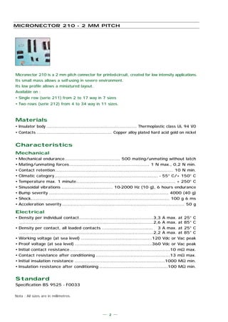
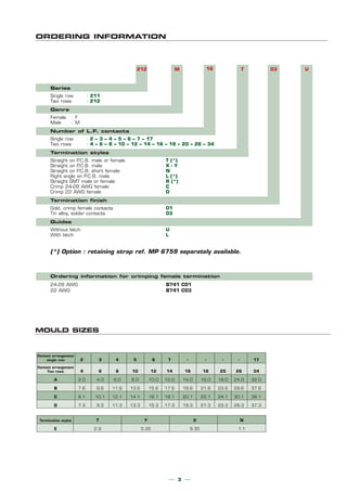


The document provides specifications for the Micronector 210, a 2mm pitch connector for printed circuit boards. It is made of thermoplastic and copper alloy contacts, and is designed for low intensity applications in severe environments. It comes in single and double row configurations with 2 to 34 contacts. It has mechanical, electrical, and climatic specifications listed. The document also provides ordering information, mold sizes, termination styles, and PCB layout recommendations.


