SlideShare a Scribd company logo
1 of 64
Download to read offline
~
-
®
 Q..S-t Gou~on f .!,
F~e..?o.. '1'0.;;'0'
J
® ?biR L '"(0 C.Q. d.l.LH e
ou) d f-uS t' ')d
tlrQ.T<lh>'(
"
-pG.'tt Cd~
p~,t- 0.w
~ A"rt-iLl2..-1
~ A'It-I c..~ -·Il
~ 1"(;Ic.. Q... 1
'( fyti c..IL- '-.J
~ t,--cQ...-"
p@..t- ~£:
~ A"r'" i CQ...
WI1-Id ih
3 I f),(o,L.-iY>3-
p'w ~Q..du.y~ , ~dJu , "vVo... d.-
' d
CONTENTS
G Q...'() Q.tC 
W Q.. dn~
I.i~ Q..  d.. t no
-.j
wf>3
W~B.
NQ...d.nj
SN ".s~
A
8. w -  0 '2-
~Q-
5 p a.. LI r-ic..o<-i::
' o n
?'tfovd.1 flj
,
VI
MQkQ 1"  (). 
YI"f"imu.vY f1c oi
Ro.v,qL 0
Va., i £X.k)  e..S i' t:-'cJ::
of
j 0 i fit
n o.
~
01"1 ~ t)y IVO" Q
'oQ.... V ~ ILJ to
fOV RrV1..> _
-
bI..Lt'?o'i 0 V ~ 0 "
t;<w- ~
W Ps .
, ,
J or ",i Y"lj
c..Ot.~bQ..
Pf R r 0 P-. N At.i L E=
8 ucd 
'~ ""'j --t-h Q..
:::0
OL"3 ,- Vo..'Y IOLb' Q..
"(,o....s,ut-t,, ()f Y ~.,u '(' ILd
Q 0 1'-) 1.-'1. r '} C 1-'1 Tl Of!
W he LV I' II
~  - , Q J Ot r. cI- tt-,/I2.,
b~-bh' ''j' Gvnd ND'E
:;;'I:l ofFo.-t..-t 'Iv, e.... 'V QC-kC!<Y' e.o, ) ~"r 0 pc;. ¥ ;j 0 - tv.,,_
~ 0 ,'('t!, t 0 Q. y t--.a.n ~ 'fY' r Q
,,,...t )
I~
g .;'4.k 1tr,.,,--
6l. &t -  0 b 0 ..J0. v, ;. '"Lo..{. , 'i) ",
t:Xc,, - o6. ? ,ccc Ju.'r ~
NDT
I
O~
WI 
,
 ¥-€. Su.~rOl4>-
 lAb ~'" .
OJ ,
.D ~ r T N I T I O ! f !::,
~ IV CI ,' c '-,  v t--,  Q
-'- /'- - OIW ..- 0 I ' 2
W Q.. d
'S) <L - Q....ck ~ .
~ Q..... d.,> c....c"" bi VI u.k Q:1
"r0 l Y li-Q_
t
; OvY J-o,.¥" d ~ ¥:)
.__ I?J<lOd
~~~
~
------lt
wS '-....1)1 N &1
ew- i2...1
A RTICu= - L
P DbI T loN $:
G tv1 QaJS Butt wQ..J
NtD<.n.':. f'ict wold
+6tC~w- 4bl-.3Cd)
----- CfE)
r-----rl::........---,----. _---'----"-4 rc-(IS(W ...4 bl5(..:1)
C...PD) ;--- -.r-------;r
 Gr C
blw "'4bl-3Gar-___
(P A)
~W-2...2. PlPE POSTrIoNS: _
(j 6 I 6
~ ~ R)t~Q...d
 &![~W - 4b-4L/lD
/
SNo
I
3
~
5
10
T
 
1)1 A-N D N j)"lf
(5(vJ-I5"O
~w- IbO
I3.vJ - t1-0
~w -~O
8.w - 'i12..
6vJ -g-~
(5( AI -  g- it
6>w -  Cf 0
B,AI-'1I· 
~V'J-92-
TEN Sl:. 0 1'1 T t:- .s, _________________.-;» EX. vJ -  5 3
C51IJ'IDED- '6~lD - I;-.sTS______________;>QvJ-Ib3
LM PACT TE- ST _________________?'5+' 'E:c..'-ll"-:LC.IH:rol
~'"I LLf:T_ WE L}) TEST
1-l2.I'c...TtJQ..c TE-ST
M ~ C-.RO f XAVVl"LNI'l-TIOIJ - PI<.0 C J;J)JRIE .s?~ c..1 'J)fN ---7 (8 VJ - I If 2)
M 1'1 eRO t:: )I. FtYV1JNfTT']:oi') - fSR Z-o<.Ml'I-rk./? Sl'EC.t:VV1t?N > (tx vJ -9" 4-
OT-T E R T'E- f:,T
K0 ~' D.5'C.f~,,'c.
V I~o SOr,I' c..
Ex""WI ; Y cvt-I' 0., . ---------->-'>; afi _  '1  ~ . 2-
E 1-. '" yY) i Y>Dv-I' O .. . > 6(w _  q, . 2.·3
V'1. SJ ALE: X'A-vvllN". T I oN ------------>~ aAI -  ct 4
~II!XJTJ) PFI'JETRA-I'lT F)(AM'TNAT.IO N > l0vJ ·-I<1S'· L°2.
M£C.HI'NJC.AL T£-ST
8. 11 .,  5" 0 'T RAN 5 v f RS E T E. N S1: L E T [;-ST S '
'To ' -
Shvw -n.12.. Sh~-h--. b~ n,.Q.... JOin,.
'RL 1)cc..s ij ,
u'T S::i> Loa J
CSA
<b< w - 5:3 AC-Lt; PTFlNC.E
,..,-. ~ tL- - 0. '"- j:l.?-P~  oo.J
S, Q...m'o nAyI2A
(,0 No t PQ..ow 1--.Q.. ::,ClL.',e. Vuo. TQY.'>"e,. s,h-~-t"
~) A :-~t 9 1. D~ "Ir.~ Bo<'se. /v',uo,} TQ.j'!:'( k
ASM EO -I X "av6Q. 6i IV -422-
ASME -}LA lc.on a.6?ontY'2,J YlCI,-1l."('io. 
(5w-bO
Tu
I) 5'clQ.. 3Q...nd Ta-,St
:?-) Root b Q.y,d T I2-bt CKCC t T QY ::, i on)
(}) f 0.. CAL B"-,-;J T 12.6 t- l to..t.A2.. 'T12..n!;,' 0"')
~:vJ -1-0 1MPAL'l" TE,ST
"
l"""'n's T~t- A~..s"-S~J
 r-- Q
(1  7 _fL J
S tD'X'oo.yd ::>
, ' yY) ? CJU.-t-  0 Q{d
CR..IT E Rl A
J0 P ~u.irtl. 'V1 2.V1 ·f (V ;) ,gPtL c... r:. icc<-l-r'o h .
exw-8 O '=' '1 LLFi 'WEL-.D 'TE,ST
fX.N -)81.. ~ 2...1' c:.T .J R. 'to TEST~ ( ONL'I wf>Q.)
'T : 6..,ou,) "t"Q. 6(vo-..Li t~ «)~ -', d ,NQ.. J
8,,11-83 MALI?.O E)I,AVVlJNA'Tfoh/ CwP.sJ
~w- e lf tv1'c....12.0 E')t AM:n'Ji'I Tro"r (wP&»
L~
bI
o'w- I G10 oTHER TG,ST5 & :.')(.RM~NA'TroNJ
&w - q ,. RA.DT D GtQ.F~ PH.rC t; ,)< A MINAT'IorJ (W pe,)
~-~·i·'2..'2.
~ CYO.C.K & LOV:) LDP
~) lJ>to 2> 'YW,,", IVi0.. ')( -'0'(
i '" LILtS' VQ.
vd
~) '11 b @$ b- foy l::
 'Y) r t<...,.. r:Q...c):-' ., n
I'-
bL
~
Ij} j}2-
1: 12..:;-
~  'is """'" J
I :'> &..
k --=f-'J- m ""
)1
PI c. c..~tQ..J .
R.0 lA Ych..J T"~' c.o...b' 0 '" :
'T..-e.... tQ..t El ~ 2, b',...., lL  l2..b,SQ. ..-
tv,a,v.-, W ;'~ tt.-.
No:::. PI c c..-up totbk.
~'1'o~
w dd rVlIvtG 1 C?) :=  0 YY1 "" th.iuc.n ~ !,
o VQ."' I ) vY "" t-v 51- lYIYh 'V1 c.. USJv,,-.
t'v,ex;t om·<2fj ~
IQ..Y>J p., 0 f I L. t·
b. L.
J;.J  +~2.. _ t
j)  -::> ~ I}.""VQ.'( y>'<2A.k'.,,, 
.D 2. -? l ....... 'l'1e"" 17~'o", 'L
.L -? L " '') l1.6 t J
' "Y) pc{p>,c.t-<'0
"
¥::
2-
~
~ ""'3' .3 1
k ~
+2-
Faj
2
1
D1+D2<6mm D1+D2+D3=8>6mm
cxw- ~2 ULTRI1~DNU... E1<.AM1NlqTTON L wP&j
~W ...'Q ·2 -3 Acc...C-{J~C>VCQ.. L..1f"ctto...YI'o..
GoLAfO"'~ ~ho.
No
(Y, 'I'Y' f' ~ j 0 I'n. t:
'1......b~.-O~Qh~..tfO': I X - , S-- D4
A
0' ~~~
O' DO t
A L<..
 )(
2- &w - 4-03
3 ~w - 404-
4- G(w - 4 D5
5 8.w '-4ob
b 8u) ·- 4-D1
':J. Gl. tv " 4 0 g
% ~w- 40Q
q ~W-4-10
0 eW ,-50
 &w - bO
 2. 6 i~ .- n -
D
3 ~w - 160
J.. 6w - H~ 7"
S ~lJ - 23
b txw - &4-
1- fX w- 90
'" @?w-!9. 
.1. law"  "I , .2
It? aw - Cf ),.
11 61."'-' - t9S
ARTI CLE 
iJ E LD'1 fl ("1 .)F T f
JOTN,-S
816£ IVIETAL,S
~TL-Lt:R. IvETA LS
PO~ l TIOlf,S
PRE: Ii EP.T
POST WEL.D 4 EAT TR.EATMEN T~
c,., fS
ISUSc:..iR..'LC.A L CV AR y- Ci E: Rr.sTT L!:,
Tec...H N TeLJ[
TEN £>1 L€ TEST
G-t U1::DE.:D - .BE ND 'T E.S'I
r-RAC.TURE TE6T..,S
M AeRo r-OR PRD c...Ej)JRE ~PEC-ltlllE'NS
/VlACJ2.. D f='oR PER~oR1Vlnllc.£ Sf'SC-'l.-M E I'/..<,
Ra.J..io-Q---Dph' c... r
w C Xo.lY{no.b'c'r
U'l b--Q
5cr, I L Exo.'V)'"eU::-,'1!) V
V'CB,UR..- E 'f;.A tV1:NRI.~DN r 'oR... WpG
LleJliJl.D t'ENE,RA N 'T BXAI'V'lI'J~TrON
RU~J1'REJ)
HlR~S
~w-4g3
reAR
exUl -402-
~vu - 403
exvJ .- A-D4
(B,w - A-cS
txw- 4-0b
(8w - A07
t9-w - J- oQ-
t9vu .- A-og
~w - 4-0
~w -- SO
~w ·- bO
C6< vV -  ":tv
(0v...' -  ~ ()
6w-92-
~~ - <13
txw-~1-
~w -  ~'1
:J>IT A AND
~w-4-~2-
e,w-4D2.
l8.uJ- 403
(8.w--4-0 lj-
0...w - A-°S
~uJ- Aob
(B.w - 4 0 7-
~vJ-4-og
l6I.vU - 4 D<1
~u) .- A-O
T E-ST lW'Y..s)?(x'K. JWP!Q)
~w -4~L~-A /4g,4B
'>Q /-~
r&
~Vv- q
9w-~4-
~v.J -  q L.-
PI l,z I lCLt= -IT
~
vJ [LDfNCl PRO CEDul2f QU A /...I FTC14ILO/-
""I(>JJ; ')d Vo.n'ocb t~
¥'-/IZl'tY'fl . T DAb 1
~ -~
- '- -2 S-2 thyt) ~
T%IC2-- 2-'33 - S tv) A W
Tovb~- 2S"b - GiTfW
ARilCLE -  11
~'vJ- 30 J
tXW - t, OI. ......:"':.I2.V1 t o~ I Q.jt-
W '? ~ Q. YQ. ,'<'>to..", cllL-d {;;c ~~Y) do~
e...AI -30 - Z $..v..Q. 'i'~ Q4b'Q '" T~ t:, : ' R~w'YIUv)1l..M t- ~ ,
-::> wP ~ @Y') ~WpS
Vo 'rI' ocb l ~ T0I.b 1,<- '3 S o
~0 .. VVlovt- !:, - ~1/ - 4 ~4A- / fXw - 4~Lj 13
S,NO
3
.- 2..52
:;0
:W -'353
8.w -'354
0-.w-3S-~
0(.-->""-- - 3 5 b
evJ--35":f
-  b
~~ - 432.
C. ON TE (ITS
10..,;-etbIC-6. poD c..~ 0...-0 Q.
LvJ?5)
ts sQY)t1c>  V<Ay ,'o.b)e.. O,
- W LvJ?G.)
SS-SQ.X):;;", Vo-ol'c.bk "11 Q.)
Eo f)SQ.)')'bo.) V",-'O,'o..btQ. g A-W lVv'P a)
::.::'SQYI~a. r-Jo..o'ot:,lQ.. t=c.AwLWf>~)
ES;'CQ...YIt-,o, Vo..,,<AblQ.. f:,-w &J
~5'>Q.Yb6.  Vo.y,·oYo1Q.. 'P It:, vJ CvvPG.J
i2. TYO .0 ?- l) D GYO '-"f1' '2J b ~ 'b ~ IL Vv) ~  S
f- '" y ~ VI. 0   y: ,'c.cvL-; 0 n '-~ b:..D1N ~)
D~ ~00 tz...
~v.a>.l.i ~; c.q..h 0 h '--'-"'L""""I 7.:rrl c;;,)
5-No 'T%~
6
&v! -4S
8,,~·· 45  . 
9"vJ-LSI ·3
~vJ - t>,..s-~ A
(~w - 4'02·  Co.)
A tQ.'( "OJ:;tl.. ';- f'...lo
R AovU·f.i ~'D V
C(),ssIFc.~'o'" or: rQHO~
A",o.-j ~ S to.. ?'(D CCLdu o(L
t IS. - NAVV'lb Q.1'-")
b<l...r.d cA.t
~i ~ .AJ Q...J 'Q.6 t.s
WCLJ MQj;-o..
19uoJj t- " c.o..b'O'l
? E..R~<D R IV AN C. E aVl"lL1.~1: C..-1T1.or...! TI-I1c....KrJG5J
-1- "VI r T.s '" Nj) 1::S .s~ :cc.:C MEr.'.s -
ID-b~
~r;.;;
- 452·  (j,
~w-452...- 3
Qw -.4-52...-4
~v-I -452...· 5
to..w - 4-5 '2.. . b
e'IN-4bD
G<w-4 b
G,Jl -4-6•
Sly,) _ 4-b1 2...
<6w -4-)3
6(v-J - Ab ~
(£XV'! - 461·5
S-vJ-t-- '0 · 6
fJ-.w -4bl .+
(9w - t-b' g
Qvv-4bl ·9
~,oo Ie... - W del ~ o..m~'"
3 "'"().,) IXo.."fY) I2ku-T ~    Q.k- _ W Q.. d o...-s :;
Nf!:> /'vJPtX. trvlc..k."'~s.j Limit-s OYLJ T e.st
S"Q...OM~Vl.s~"<" OvQ.....,(j-S
Or RA ?- lC!,
Po b1.r r ON~
-?o.btn' o~ Dy wQ..dtJ - GnoOlQ.. WQ..d S
t'm..:,ttl'o"1S D~ wQ..~.!:, -r;Q1- we.JJ.t,
G.oovL we..<:b ' '0, 9)ovI..~- T~.)t- >o.)lb' o,,",
G,OO'l''I<... wQ...1.s In ?I?Q... -Q.oc ,?o.s.i~'''''''
f,* W'Q...d.:, iY p'lo...bL -T.u..st- ?O~t-lo'n
rc; Q.t- ;.J Q d~ i Y '? ? (L _ " Q.:' I:: 'fooS i tl 'OV S
Stud vJ lLcis - T<LS t ?<o s- t-io'n.s
St-uJ w !2..clS _ W Q.  ~ "'-.'j '? <0 oS i' to' 0 "
rJ?G,. - ?<c.:,b O '" Q..Xd 1)OY'IQ.D2.x Lmih::"b'Oy))
D
~vJ-4b2.
(Xv-.! -4b2.  CO)
~V'-i-4b2.·  (h»
Q.w - 4b2.(.c..)
6(v-J -4'0'2..  0)
15<1'.1 -41:>2.. l~)
QvJ -4k>2. - 2..
~ 'v'-.i-t- b 2. ~C.o·)
(8v0-k b2 3(b)
ew -4b2.A (a)
~ W - 4b 2.-Alb)
I9w-4 62.. -A (c..)
~w -46 2 40)
(fAw -4 b 2..·5 Lo..)
G-VI - 4-b'l. 5" c..c.)
tXw - Ab2..-S Cd)
&.w -4 b 2.S LC2.-)
T a...Y'>s, "0 Y' • RQ...d1Ac..e.cl SQ.t.b' 0 n _ .plo.k42..
T<Q..YS'on _'L 'uc..-  S~"L IS"
~ "'-0 ~on _ ,lop:..
T C2...Y SIOV - K<WUC-W S Q..W 0 '" A H-o.y~ ~.. Pl'pe.
T(LI'S~'" - RM'-AC_:Q.cl SlU..toY' - TU.l"'DI2..J Sr'wYnQ...Y.)
TCL.Y1-.S' OV1 - ~v. SQ..t.kiol" _ SY'YCA) j)o..YYlWLo pl~
SidQ.. E,Q.hd
y:'o c..e.... O-.n d RdlO t- b Q..hd. b - ',0..'"6 V Q.~ S e..
f'o. C-Q..
OXJ. -R<:>v t- E:, Q..Vd S - L<tl ~ i b-IeLi no.)
~ ', h .t w Q..J.s
.
Pcx..t--Q.. ? Yo C-Q..o l.l re...
In -
-Io..t WI2....J::,
- ro..h.. _ ~ Q.. 'fD" 'Y'Gn ~
IY'
t=";~ W Q...-6..) - pI/I2.. - ? Q...'6"(-0 '(NI 0.1' e-e
IY'
vJQ.ci ., - ,
? '6" ') c...Q... 0,Ye.
~~ '" ?lpl2..
C~I2..Nc..Q. AY",:~S D.lrd -a.,dl>~ S'fwyY)~'"
~ 0'( QI Q.'& e>..j S.
C ~ 12....VV i ':0.  AY)C>.~ -" :..>! ~o..yd ) Q...~ ~ r M",c... ¥ 0  0 c.cx.-:-to Y
<>6 '0 "Q.'(~
t>? 12.. 16Q.Y'0 ~ Ii' Q.. c...i m QX - we..: 0 YI2... )o.,~
? <>-tu... 'b o.Y d S rCQ. c.. «1 Q.X) .:" w "-0 Q v a..Y  ~
I( cJ-t,. M "'.::" 0 ( 't- 0. ... dV oh1 , L h Q m "cov1 S -t' I2...U ' rY) "-""
~G' 'V-J12-d fQ/o..'(~
Gw-4b3·1(0-)
(9 vJ- 4b3-ILb)
(1;( rJ • -4b3  C.c.)
eV'J- 4- b~'  C)
EXvv' . 4bo·2.- Co-)
~ 'vj - .; I?3 2-Cleh)
1'Xv0 - 4 ,Gk,. 7>
~ ~~ - LQ..s,.:, ~  <1 YV'I'<V 'v( ? 61 R 1fl1, t- ?IIW- LC.a.h'o",
~i oJ::e. _ M "..-Q... ~(lA,V  a, 'Y'I VY ~<. f'R C '~-- pIa.v-<- LcQp./:-to" .
Picvbe. _ Lv"'3;t~'Y'lo. f y-o c..cdv.",,- ~' (=-:QoJ,.'0'"
 "'-0 ~ P 
'Q... 0e.. L0 ~-v Y"
L-0 c.cJ::t'<0 Y'I •
? a.ke.. LIU-:S -tv,"""  '1 Yy) IV th ~<- ?11-y Y:o '( VY GU ~
(fX u. ~'-  c.q.,t--,''"'" Ro", t- (-0.. tA2. b 12-1' J T ~ 1: Sf ,,,.L;m """
L-O o:>.-h' "V' .
?~ ::::.. o,WYV "'~ flO..'<'-o'('''IOvr'c.-.e. C8...~'I-'~'o...
S 1c t2... 0 .a..", J S?Q.. cJ '(Y) Q...Y'  U-b :. S f ~ m '"-" Lo c.o.h'0"
~ ~ - LOV'3b.lcLi ~  ?0- 't '-0'(" yY') a..fI CA:2.. 8.~' fl co.lo'.?.,
0.6+ 3?<2-u<Y<V" La C.cJ-IO.. .
,
M a.c..r0 3rI:U:..:"", a..>' Fo.,... f I P~
~ V Id<1.J 'b!2XJ
5No
1
2--
3
A;-
5
e;:xw- 4'D 2-
ew --40 3
8.'1-- A; o.q
(!xw -- 4D5
(QvJ -- 40 b
ExW -- 40 ~
Qw -- II 09
exw -- 4 10
.~ ELP'l N G,
Jo1. '".1 S
J) ~TA-
Ro.~Q;1rQXCI2..(Ace... .s+J
______---------~7 S?Ec.l~1 CRTIO'I /'J)'KAvJI.NJ
BAS't: rv' t:T 1'1 L- S
___________-kAoS N G-11i., l.0.-- 6<w--422...
~----------_~
' /ASI'V Go -- i.C- ,J.'1--._- G.vJ --43 2
~l....L El<- Mf-TP!LS
PvS'L- ,10NS C
f?L-A' r= JF'1~S)-
l?R~ - £p.,"
_-------,)03- -- ~w -- 4 bl 3 /rrxv-J--4b1 ·LJ..
_ _ _ _ -----------JJ~PW-- ~ 1'111 AI'' Q.1'6,< -- R
'2>31-3 _>1o-b1o... 33°' . 
VW~--------------------1F~~
3~
.~I~~?=-
=
~
~
~~
3
~
.;
4~1~
'{ill--P"d-- -? uC--S -51:/VtlA --32
~32:, --;>To.bo... 331·-
Gr RS_________________L:
10
31
. I --7 Tctb t2-  3 2...
~c.. '7 SI=-R-53z-
ASME BPVC.IX-Z015
(15)
FORM aW-482 SUGGESTED FORMAT FOR WELDING PROCEOURE SPECIFICATIONS (WPS)
(See OW-200.1. Section IX. ASME Boiler and Pressure Vessel Code)
Organization Name 8y
Welding Procedure Specification No. Date Supporting PQR No.(s)
Revision No. Date
Welding Process(es) Type(s)
(Autom. tic. M. ny.... Mac"'ne. o r S~mi·A"tom.'io)
JOINTS (QW-402) Details
Joint Design
Root Spacing
Backing: y" No
Backing Material (Type)
IRcfur to both bading.no <I'.,M'S)
0 Metal o Nonfusing Metal
0 Nonmetallic o Other
Sketches. Production Draw ings, Weld Symbols, or Written Description
should show the general arrangement otthe parts to be welded. Where
applicable, the details of weld groove may be specified.
Sketches may be attached to illustrate joint design, weld layers. 3I"Id bead
sequence le.g., for notch toughness procedures, tor multiple process
procedures, etc.)}
· eASE METALS (OW-.403)
f:l "" - 4-2-2-
P-No Group No. toP-No. Group No.
OR
NQ"M IL I£.i Y-~~ A t,IVI r:i 1I A
Speciflcalion and type/grade or UNS Number
to Specification and type/grade or UNS Number
OR
llSMr;; -Ir{j
Chem. Analysis and Mech. Prop.
to Chern. Ana lysis and Mech. Prop.
Thickness Range:
=fo.blQ.. 61w-A51 '  "TunQ eW-A St- 3
Base Metal: Groove Fillel
Maximum Pass Thickness ~ 1/2 in. (13mm) (Yes) ___ (No) ___
Olher
"'FILLER METALS (QW·404)
,,~V/"- ~~l'0
2
Spoc. No. (SFA)
AWS NO. (Class)
-ornwo ~:Li7:?
F-No.
A·No. TlLlolo _ "'W - AA-"
Size of Filler Metals
Filler Metal Product Form
Supplomental Filler Metal
Weld Metal
Deposited Thickr.ess:
l-r,.. ,, 112- _ Cl'hl _-4- c::.1• I
Groove
Fillel
Electrode·Flux (Class)
FluXType
Flux Trade Name
Consumable Insert
Other
~Each base metal·fille r metal combination should be speCified individually.
(07/15)
307
~
n
2
o
-
r
n
0
~
~
"
".
~
"
A.SME BPVC.IX-201$
~
B
~
~
B
~
m
~
FORM QW-482 (Backl
WPS No. Rev. ~
n
-- 
B
"
•
B
~
~
POSITIONS IOW-405J POSTWELD HEAT TREATMENT (OW-407) ~..3 '~3 -;>To-b 12.. :'>2
Posilion(5) nf Groove Temperalum Rang"
Welding ProgresSIon Up OO~ Tlnlll Range ~lB I !:!'":1. 0 tl CS- 5 b 0
C
Position!,) Of Fillet Other U 't B - "02
;!.
<
B
"
•
~
~
~
'"
~
0
Other
GAS (OW-408)
S~ 1' -S;,~,~coY:}.;:EO·TIc..)
PREHEAT (QW-406) B
3'l ..3 OT«.bI<- 330-' I
Pr eheat Temperature, Minimum a Gas(es) (MiJ(ture) Flow Rate
Intarpass Temperature, M aximim t.. ~Wt;.~_J) 1.. .
Preheat Maintenance tv Q'" Mt1" ::J Ap ~O Shielding
Olher Trailing
"
0
'"
0
(Continuous or special heating, where applicable, should be specified) Backing
Other
cr
~
ELECTRICAL CHARACTERISTICS IQW-4(9)
~
0
iii
0
"
~
~.
B
Filler Metal Olher
(e.g . Remarks. Com-
'"
".
~
~
n
Current Wl/e Fe&<! Energv Dr Travel menrs, Hot Wire
Wetd Classifi- TVpe and Amps Speed Power Volts Speed AddIt Ion. TechnIque,
Pass(es) Process cation Diameter Polarity (Range) (Range) (Range) (Range) (Range) TOlch Angle, etc.}
5'
~
f
;;
n
"
Ampg and VOlts. or power or energy range, should be speCIfied for each electrode $i~e, position, and thickness, etc. ~
"
B
:!
Pul$ing Current Heat 'nput Ima)!:.)
n
0
e
Tung!len £Ieelrode $ '1.e and Type aJ;,YV1 ( -1T C S!;~ - S ' IL
.""'.. , ......... 2% Thoriol.... etc.1
~
Mode of Metal Transfer for GMAW (FCAW)
tSp••v A
,C. SI>ott C"""'~"" ~ eteJ
•
~ h9r
n
0
~
TECHNIQUE !QW-4101
~
~
0
2-
String or Weave Bead
Orifice, Nozzle, or Gas Cup Size
0
m
~
Initial and Interpass Cloaning (Brushing, Grinding, etc.)
. - B
~
Method of BaCk Gouging 0
OscillatIon
"
N
0
Cont ~ct Tube to Work DIStance
MultIple or Single Pass (Per Side)
'i'
0
~
MultIple or Single £Iectrockls
Electrode SpacIng
Peening
~
0
~her ~
~
~
W
~
'"
~
0
(<l7/15)
0
cr
~
m
~
"
0
"
N
B
~
C
•
m
"
~
0
~
m
"
m
iC
~
"
308
0
~
z
0
~
r
Table QW/QB-422
Ferrous/Nonferrous P-Numbers
Grouping of Base Metals for Qualification (Cont'd)
Spec. No. Type or Grade UNS No.
Minimum
Specified
Tensile, ksi
(MPa)
Welding Brazing
ISO 15608
Group Nominal Composition Product Form
P‐No.
Group
No. P‐No.
Ferrous (Cont'd)
A/SA–508 4N, Cl. 3 K22375 90 (620) 3 3 102 3.1 3.5Ni–1.75Cr–0.5Mo–V Forgings
A/SA–508 3VCb K31390 85 (585) 5C 1 102 6.2 3Cr–1Mo–0.25V–Cb–Ca Forgings
A/SA–508 3V K31830 85 (585) 5C 1 102 6.2 3Cr–1Mo–V–Ti–B Forgings
A/SA–508 5, Cl. 1 K42365 105 (725) 11A 5 102 3.1 3.5Ni–1.75Cr–0.5Mo–V Forgings
A/SA–508 5, Cl. 2 K42365 115 (795) 11B 10 102 3.1 3.5Ni–1.75Cr–0.5Mo–V Forgings
A/SA–513 1008 G10080 42 (290) 1 1 101 1.1 C Tube
A/SA–513 1010 G10100 45 (310) 1 1 101 1.1 C Tube
A/SA–513 1015 G10150 48 (330) 1 1 101 1.1 C Tube
A513 1015 CW G10150 … 1 1 101 1.1 C Tube
A513 1020 CW G10200 … 1 2 101 1.1 C Tube
A513 1025 CW G10250 … 1 2 101 1.2 C Tube
A513 1026 CW G10260 … 1 3 101 11.1 C Tube
A514 Q … 100 (690) 11B 9 102 3.1 1.3Ni–1.3Cr–0.5Mo–V Plate > 21
/2 in. – 6 in. (64 mm –
152 mm), incl.
A514 Q … 110 (760) 11B 9 102 3.1 1.3Ni–1.3Cr–0.5Mo–V Plate, 21
/2 in. (64 mm) max.
A514 F K11576 110 (760) 11B 3 101 3.1 0.75Ni–0.5Cr–0.5Mo–V Plate, 21
/2 in. (64 mm) max.
A514 B K11630 110 (760) 11B 4 101 3.1 0.5Cr–0.2Mo–V Plate, 11
/4 in. (32 mm) max.
A514 A K11856 110 (760) 11B 1 101 3.1 0.5Cr–0.25Mo–Si Plate, 11
/4 in. (32 mm) max.
A514 E K21604 100 (690) 11B 2 102 3.1 1.75Cr–0.5Mo–Cu Plate > 21
/2 in. – 6 in. (64 mm –
152 mm), incl.
A514 E K21604 110 (760) 11B 2 102 3.1 1.75Cr–0.5Mo–Cu Plate, 21
/2 in. (64 mm) max.
A514 P K21650 100 (690) 11B 8 102 3.1 1.25Ni–1Cr–0.5Mo Plate > 21
/2 in. – 6 in. (64 mm –
152 mm), incl.
A514 P K21650 110 (760) 11B 8 102 3.1 1.25Ni–1Cr–0.5Mo Plate, 21
/2 in. (64 mm) max.
A/SA–515 60 … 60 (415) 1 1 101 11.1 C–Si Plate > 1 in. (25 mm)
A/SA–515 60 K02401 60 (415) 1 1 101 1.1 C Plate ≤ 1 in. (25 mm)
A/SA–515 65 K02800 65 (450) 1 1 101 11.1 C–Si Plate
A/SA–515 70 K03101 70 (485) 1 2 101 11.1 C–Si Plate
A/SA–516 55 K01800 55 (380) 1 1 101 1.1 C–Si Plate
A/SA–516 60 K02100 60 (415) 1 1 101 1.1 C–Mn–Si Plate
A/SA–516 65 K02403 65 (450) 1 1 101 1.1 C–Mn–Si Plate
A/SA–516 70 K02700 70 (485) 1 2 101 11.1 C–Mn–Si Plate
A/SA–517 F K11576 115 (795) 11B 3 101 3.1 0.75Ni–0.5Cr–0.5Mo–V Plate ≤ 21
/2 in. (64 mm)
117
ASME
BPVC.IX-2015
Copyrighted
material
licensed
to
University
of
Toronto
by
Thomson
Scientific,
Inc.
(www.techstreet.com).
This
copy
downloaded
on
2015-07-13
07:36:37
-0
ASME BPVC.II.A-2015
SA-516/SA-516M
930
TABLE 1
CHEMICAL REQUIREMENTS
Composition, %
Grade 60 Grade 65 Grade 70
Grade 55 [Grade 415] [Grade [Grade 485]
Elements [Grade 380] 450]
Carbon, max(A), (B)
:
1
⁄2 in. [12.5 mm] and under 0.18 0.21 0.24 0.27
Over 1
⁄2 in. to 2 in. [12.5 to 50 mm], incl 0.20 0.23 0.26 0.28
Over 2 in. to 4 in. [50 to 100 mm], incl 0.22 0.25 0.28 0.30
Over 4 to 8 in. [100 to 200 mm], incl 0.24 0.27 0.29 0.31
Over 8 in. [200 mm] 0.26 0.27 0.29 0.31
Manganese(B)
:
1
⁄2 in. [12.5] and under:
Heat analysis 0.60–0.90 0.60–0.90 (C) 0.85–1.20 0.85–1.20
Product analysis 0.55–0.98 0.55–0.98 (C) 0.79–1.30 0.79–1.30
Over 1
⁄2 in. [12.5 mm]:
Heat analysis 0.60–1.20 0.85–1.20 0.85–1.20 0.85–1.20
Product analysis 0.55–1.30 0.79–1.30 0.79–1.30 0.79–1.30
Phosphorus, max(A)
0.035 0.035 0.035 0.035
Sulfur, max(A)
0.035 0.035 0.035 0.035
Silicon:
Heat analysis 0.15–0.40 0.15–0.40 0.15–0.40 0.15–0.40
Product analysis 0.13–0.45 0.13–0.45 0.13–0.45 0.13–0.45
NOTES:
(A) Applies to both heat and product analyses.
(B) For each reduction of 0.01 percentage point below the specified maximum for carbon, an increase of 0.06 percentage point above the specified
maximum for manganese is permitted, up to a maximum of 1.50% by heat analysis and 1.60% by product analysis.
(C) Grade 60 plates 1
⁄2 in. [12.5 mm] and under in thickness may have 0.85–1.20% manganese on heat analysis, and 0.79–1.30% manganese
on product analysis.
TABLE 2
TENSILE REQUIREMENTS
Grade
55 [380] 60 [415] 65 [450] 70 [485]
Tensile strength, ksi [MPa] 55–75 [380–515] 60–80 [415–550] 65–85 [450–585] 70–90 [485–620]
Yield strength, min, ksi [MPa](A)
30 [205] 32 [220] 35 [240] 38 [260]
Elongation in 8 in. [200 mm], min, % (B) 23 21 19 17
Elongation in 2 in. [50 mm], min, % (B) 27 25 23 21
NOTES:
(A) Determined by either the 0.2% offset method or the 0.5% extension-under-load method.
(B) See Specification A 20/A 20M for elongation adjustment.
Copyrighted
material
licensed
to
University
of
Toronto
by
Thomson
Scientific,
Inc.
(www.techstreet.com).
This
copy
downloaded
on
2015-07-13
07:13:01
-0500
by
authorized
user
logan
ahlstrom.
No
fu
QW-403
QW-403
ð15Þ
that was used in the qualification test without considera-
tion of the compatibility of the base and filler metals from
the standpoint of metallurgical properties, postweld heat
treatment design and service requirements, and mechan-
ical properties.
Table QW-432
F-Numbers
Grouping of Electrodes and Welding Rods for Qualification
F‐No. ASME Specification AWS Classification UNS No.
Steel and Steel Alloys
1 SFA-5.1 EXX20 ...
1 SFA-5.1 EXX22 ...
1 SFA-5.1 EXX24 ...
1 SFA-5.1 EXX27 ...
1 SFA-5.1 EXX28 ...
1 SFA-5.4 EXXX(X)‐26 ...
1 SFA-5.5 EXX20‐X ...
1 SFA-5.5 EXX27‐X ...
2 SFA-5.1 EXX12 ...
2 SFA-5.1 EXX13 ...
2 SFA-5.1 EXX14 ...
2 SFA-5.1 EXX19 ...
2 SFA-5.5 E(X)XX13‐X ...
3 SFA-5.1 EXX10 ...
3 SFA-5.1 EXX11 ...
3 SFA-5.5 E(X)XX10‐X ...
3 SFA-5.5 E(X)XX11‐X ...
4 SFA-5.1 EXX15 ...
4 SFA-5.1 EXX16 ...
4 SFA-5.1 EXX18 ...
4 SFA-5.1 EXX18M ...
4 SFA-5.1 EXX48 ...
4 SFA-5.4 other than austenitic and duplex EXXX(X)‐15 ...
4 SFA-5.4 other than austenitic and duplex EXXX(X)‐16 ...
4 SFA-5.4 other than austenitic and duplex EXXX(X)‐17 ...
4 SFA-5.5 E(X)XX15‐X ...
4 SFA-5.5 E(X)XX16‐X ...
4 SFA-5.5 E(X)XX18‐X ...
4 SFA-5.5 E(X)XX18M ...
4 SFA-5.5 E(X)XX18M1 ...
4 SFA-5.5 E(X)XX45 ...
5 SFA-5.4 austenitic and duplex EXXX(X)‐15 ...
5 SFA-5.4 austenitic and duplex EXXX(X)‐16 ...
5 SFA-5.4 austenitic and duplex EXXX(X)‐17 ...
6 SFA-5.2 All classifications ...
6 SFA-5.9 All classifications ...
6 SFA-5.17 All classifications ...
6 SFA-5.18 All classifications ...
6 SFA-5.20 All classifications ...
6 SFA-5.22 All classifications ...
6 SFA-5.23 All classifications ...
6 SFA-5.25 All classifications ...
6 SFA-5.26 All classifications ...
6 SFA-5.28 All classifications ...
6 SFA-5.29 All classifications ...
162
ASME BPVC.IX-2015
Copyrighted
material
licensed
to
University
of
Toronto
by
Thomson
Scientific,
Inc.
(www.techstreet.com).
This
copy
downloaded
on
2015-07-13
07:36:37
-0500
by
authorized
user
logan
ahlstrom.
No
fu
ASME BPVC.II.C-2015 SFA-5.18/SFA-5.18M
481
TABLE 1
CHEMICAL COMPOSITION REQUIREMENTS FOR SOLID ELECTRODES AND RODS
AWS Classificationb
Weight Percenta
UNSc
A5.18 A5.18M Number C Mn Si P S Ni Cr Mo V Cud
Ti Zr Al
0.90 0.40 0.05 0.02 0.05
ER70S-2 ER48S-2 K10726 0.07 to to 0.025 0.035 0.15 0.15 0.15 0.03 0.50 to to to
— — — 1.40 0.70 — — — — — — — 0.15 0.12 0.15
0.06 0.90 0.45
ER70S-3 ER48S-3 K11022 to to to 0.025 0.035 0.15 0.15 0.15 0.03 0.50 — — —
— — 0.15 1.40 0.75
0.06 1.00 0.65
ER70S-4 ER48S-4 K11132 to to to 0.025 0.035 0.15 0.15 0.15 0.03 0.50 — — —
— — 0.15 1.50 0.85
0.06 1.40 0.80
ER70S-6 ER48S-6 K11140 to to to 0.025 0.035 0.15 0.15 0.15 0.03 0.50 — — —
— — 0.15 1.85 1.15
0.07 1.50 0.50
ER70S-7 ER48S-7 K11125 to to to 0.025 0.035 0.15 0.15 0.15 0.03 0.50 — — —
— — 0.15 2.00e
0.80
ER70S-G ER48S-G — Not Specifiedf
NOTES:
a. Single values are maximum.
b. The letter “N” as a suffix to a classification indicates that the weld metal is intended for the corc belt region of nuclear reactor vessels, as
described in the Annex to the specification. This suffix changes the limits on the phosphorus and copper as follows:
P p0.012% maximum
Cup0.08% maximum
c. SAE HS-1086/ASTM DS-56, Metals & Alloys in the Unified Numbering System.
d. Copper due to any coating on the electrode or rod plus the copper content of the filler metal itself, shall not exceed the stated 0.50% max.
e. In this classification, the maximum Mn may exceed 2.0%. If it does, the maximum C must be reduced 0.01% for each 0.05% increase in
Mn or part thereof.
f. Chemical requirements are not specified but there shall be no intentional addition of Ni, Cr, Mo, or V. Composition shall be reported.
Requirements are those agreed to by the purchaser and the supplier.
2.4 ISO Specification. 4
The following ISO standard
is referenced in the mandatory sections of this document.
(a) ISO 544, Welding consumables—Technical delivery
conditions for welding filler metals—Type of product,
dimensions, tolerances and markings
3. Classification
3.1 The solid electrodes (and rods) covered by the
A5.18 specification utilize a classification system based
upon U.S. Customary Units and are classified according
to the chemical composition of the electrode, as specified
in Table 1, and the as-welded mechanical properties of the
weld metal, as specified in Tables 3 and 4. The composite
stranded electrodes and composite metal cored electrodes
covered by this specification also utilize a classification
system based upon U.S. Customary Units and are classified
according to the chemical composition and mechanical
4
ISO standards are published by the International Organization for
Standardization, 1 rue de Varembé, Case postale 56, CH-1211 Geneva
20, Switzerland.
properties of the weld metal as specified in Tables 2, 3,
and 4 and the shielding gas employed.
3.1M The solid electrodes (and rods) covered by the
A5.18M specification utilize a classification system based
upon the International System of Units (SI) and are classi-
fied according to the chemical composition of the electrode,
as specified in Table 1, and the mechanical properties of the
weld metal, as specified in Tables 3 and 4. The composite
stranded electrodes and composite metal cored electrodes
covered by this specification also utilize a classification
system based upon the International System of Units (SI)
and are classified according to the chemical composition
and mechanical properties of the weld metal as specified
in Tables 2, 3, and 4 and the shielding gas employed.
3.2 Electrodes and rods classified under one classifica-
tion shall not be classified under any other classification
in this specification, except that composite stranded elec-
trodes or composite metal cored electrodes classified as
E70C-XC [E48C-XC] may also be classified as E70C-XM
[E48C-XM], or vice versa, provided the product meets the
requirements of both classifications.
Copyrighted
material
licensed
to
University
of
Toronto
by
Thomson
Scientific,
Inc.
(www.techstreet.com).
This
copy
downloaded
on
2015-07-13
07:14:57
-0500
by
authorized
user
logan
ahlstrom.
No
fu
SPECIFICATION FOR CARBON STEEL ELECTRODES AND RODS FOR GAS SHIELDED
ARC WELDING
ASME BPVC.II.C-2015
SFA-5.18/SFA-5.18M
482
TABLE 2
CHEMICAL COMPOSITION REQUIREMENTS FOR WELD METAL FROM COMPOSITE ELECTRODES
AWS Classificationa
Weight Percentd
UNS
A5.18 A5.18M Numberb
Shielding Gasc
C Mn Si S P Nic
Cre
Moe
Vc
Cu
Multiple Pass Classifications
E70C-3X E48C-3X W07703 75-80% Ar/Balance 0.12 1.75 0.90 0.03 0.03 0.50 0.20 0.30 0.08 0.50
CO2 or CO2
E70C-6X E48C-6X W07706 75-80% Ar/Balance 0.12 1.75 0.90 0.03 0.03 0.50 0.20 0.30 0.08 0.50
CO2 or CO2
E70C-G(X) E48C-G(X) — f Not Specifiedg
Single Pass Classifications
E70C-GS(X) E48C-GS(X) — f Not Specifiedh
NOTES:
a. The final X shown in the classification represents a “C” or “M” which corresponds to the shielding gas with which the electrode is classified.
The use of “C” designates 100% CO2 shielding (AWS A5.32 Class SG-C). “M” designates 75-80% Ar/balance CO2 (AWS A5.32 Class
SG-AC-Y, where Y is 20 to 25). For E70C-G [E48C-G] and E70C-GS [E48C-GS], the final “C” or “M” may be omitted if these gases are
not used for classification.
b. SAE HS-1086/ASTM DS-56, Metals & Alloys in the Unified Numbering System.
c. Use of a shielding gas other than that specified will result in different weld metal composition.
d. Single values are maximums.
e. The sum of Ni, Cr, Mo, and V shall not exceed 0.50%.
f. Shielding gas shall be as agreed upon between purchaser and supplier, unless designated by the C or M suffix.
g. Composition shall be reported; the requirements are those agreed to between purchaser and supplier.
h. The composition of weld metal from this classification is not specified since electrodes of this classification are intended only for single pass
welds. Dilution, in such welds, usually is quite high.
TABLE 3
TENSION TEST REQUIREMENTS (AS WELDED)
Tensile Strength Yield Strengthb
Elongationb
AWS Classificationa
(minimum) (minimum) Percent
A5.18 A5.18M Shielding Gas psi MPa psi MPa (minimum)
ER70S-2 ER48S-2
ER70S-3 ER48S-3
ER70S-4 ER48S-4 CO2
c
70 000 480 58 000 400 22
ER70S-6 ER48S-6
ER70S-7 ER48S-7
ER70S-G ER48S-G d 70 000 480 58 000 400 22
E70C-3X E48C-3X 75-80% Ar/balance CO2
E70C-6X E48C-6X or CO2 70 000 480 58 000 400 22
E70C-G(X) E48C-G(X) d 70 000 480 58 000 400 22
E70C-GS(X) E48C-GS(X) d 70 000 480 Not Specified Not Specified
NOTES:
a. The final X shown in the classification represents a “C” or “M” which corresponds to the shielding gas with which the electrode is classified.
The use of “C” designates 100% CO2 shielding (AWS A5.32 Class SG-C); “M” designates 75-80% Ar/balance CO2 (AWS A5.32 Class,
SG-AC-Y, where Y is 20 of 25). For E70C-G [E48C-G] and E70C-GS [E48C-GS], the final “C” or “M” may be omitted.
b. Yield strength at 0.2% offset and elongation in 2 in. [50 mm] gage length (or 1.4 in. [36 mm] gage length for the 0.350 in. [9.0 mm] tensile
specimen recommended in A4.2 for the optional in A4.2 for the optional acceptance test using gas tungsten arc).
c. CO2 p carbon dioxide shielding gas (AWS A5.32 Class SG-C). The use of CO2 for classification purposes shall not be construed to preclude
the use of Ar/CO2 (AWS A5.32 Class SG-AC-Y) or Ar/O2 (AWS A5.32 Class SG-AO-X) shielding gas mixtures. A filler metal tested with gas
blends, such as Ar/O2, or Ar/CO2 may result in weld metal having higher strength and lower elongation. Testing with 100% argon shielding
(AWS A5.32 Class SG-A) is required when classification testing is based on GTAW only (see A4.2 in Annex A).
d. Shielding gas shall be as agreed to between purchaser and supplier, unless designated by the C or M suffix.
Copyrighted
material
licensed
to
University
of
Toronto
by
Thomson
Scientific,
Inc.
(www.techstreet.com).
This
copy
downloaded
on
2015-07-13
07:14:57
-0500
by
authorized
user
logan
ahlstrom.
No
fu
ASME BPVC.II.C-2015 SFA-5.18/SFA-5.18M
501
(AWS A5.32 Class SG-AC-Y) as the shielding gas or with
CO2 (AWS A5.32 Class SG-C) alone. The penetration of
such welds is greater with CO2 than it is with argon-CO2
mixtures. Mixtures of 50 to 80% argon with CO2 remainder
(AWS A5.32 Class SG-AC-Y, where Y is 20 to 50) can
be advantageous for thin material. However shielding gas
mixtures of 50% to 70% argon with CO2 remainder (AWS
A5.32 Class SG-AC-Y, where Y is 30 to 50) are unstable
in the gaseous state and must be mixed from single gas
components immediately prior to use. They provide low
penetration, higher short circuiting rates, and lower mini-
mum currents and voltages than CO2 alone does. This can
be an advantage in welding thin plate.
A7. Description and Intended Use of Electrodes and
Rods
A7.1 ER70S-2 [ER48S-2]. Electrodes and rods of the
ER70S-2 [ER48S-2] classification are primarily used for
single-pass welding of killed, semi-killed, and rimmed
steels, but may be used for some multipass applications.
Because of the added deoxidants, these filler metals can
be used for welding steels that have a rusty or dirty surface,
with a possible sacrifice of weld quality depending on the
condition of the surface. ER70S-2 [ER48S-2] filler metals
are used extensively to produce high quality, high tough-
ness welds with the GTAW process. These filler metals
are also well suited for use in single side, melt through
welding without a protective root shielding gas on the
backside of the joint. Typical specifications for these steels
are ASTM A 36, A 285-C, A 515-55, and A 516-70,
which have UNS numbers K02600, K02801, K02001, and
K02700, respectively.
A7.2 ER70S-3 [ER48S-3]. Electrodes and rods of the
ER70S-3 [ER48S-3] classification are intended for welding
single-pass and multi-pass welds. Typical base metal speci-
fications are often the same as those for the ER70S-2
[ER48S-2] classification. Electrodes of the ER70S-3
[ER48S-3] classification are the most widely used of the
GMAW electrodes classified under this specification.
A7.3 ER70S-4 [ER48S-4]. Electrodes and rods of the
ER70S-4 [ER48S-4] classification are intended for welding
steel where conditions require more deoxidation than is
provided by the ER70S-3 [ER48S-3] filler metal. Typical
base metal specifications are often the same as those for
the ER70S-2 [ER48S-2] classification. This classification
does not require impact testing.
A7.4 ER70S-6 [ER48S-6]. Electrodes and rods of the
ER70S-6 [ER48S-6] classification are intended for both
single- and multiple-pass welding. They are especially
suited for sheet metal applications, where smooth weld
beads are desired, and structural and plate steels that have
moderate amounts of rust or mill scale. These electrodes
permit the use of higher current ranges with either CO2
(AWS A5.32 Class SG-C) shielding gas or with mixtures
of argon and oxygen (AWS A5.32 Class SG-AO-X) or
argon and carbon dioxide (AWS A5.32 Class SG-AC-Y).
However, these electrodes do require a higher level of
oxidation than the previously described electrodes when
using either binary or ternary argon shielding gas mixtures
per the AWS A5.32 specification. Typical base metal speci-
fications are often the same as those for the ER70S-2
[ER48S-2] classification.
A7.5 ER70S-7 [ER48S-7]. Electrodes and rods of the
ER70S-7 [ER48S-7] classification are intended for single-
and multiple-pass welding. They may permit welding with
higher travel speeds compared with ER70S-3 filler metals.
They also provide somewhat better wetting action and bead
appearance when compared with those filler metals. These
electrodes permit the use of higher current ranges with
either CO2 (AWS A5.32 Class SG-C) shielding gas or with
mixtures of argon and oxygen (AWS A5.32 Class SG-
AO-X) or argon and carbon dioxide (AWS A5.32 Class
SG-AC-Y). However, these electrodes do require a higher
level of oxidation (more CO2 or O2) like the previously
described electrode when using either binary or ternary
argon shielding gas mixtures per the AWS A5.32 specifi-
cation. Typical base metal specifications are often the same
as those for the ER70S-2 [ER48S-2] classifications.
A7.6 ER70S-G [ER48S-G] and E70C-G [E48C-G].
Electrodes and rods of the ER70S-G [ER48S-G] and elec-
trodes of the E70C-G [E48C-G] classifications are those
filler metals not included in the preceding classes and for
which only certain mechanical property requirements are
specified. Electrodes of the E70C-G [E48C-G] classifica-
tion may be classified with either CO2 (AWS A5.32 Class
SG-C) or 75–80% Ar/balance CO2 (AWS A5.32 Class
SG-AC-Y, where Y is 20 to 25) as shown by the “C” or
“M” suffix. Absence of the C or M suffix means that the
shielding gas used for testing was not one of the above
AWS classes and the electrode manufacturer should be
consulted for the recommended shielding gas to be used.
The electrodes are intended for both single-and multiple-
pass applications. The filler metal supplier should be con-
sulted for the composition, properties, characteristics, and
intended use of these classifications (see A2.3 for further
information).
A7.7 E70C-GS [E48C-GS]. Electrodes of the E70C-
GS [E48C-GS] classification are composite stranded or
metal cored electrodes intended for only single-pass appli-
cations. The electrodes may be classified with either CO2
(AWS A5.32 Class SG-C) or 75–80% Ar/balance CO2
(AWS A5.32 Class SG-AC-Y, where Y is 20 to 25) as
shown by the “C” or “M” suffix. Absence of the C or M
suffix means that the shielding gas used for testing was
not one of the above AWS classes and the electrode manu-
facturer should be consulted for the recommended
Copyrighted
material
licensed
to
University
of
Toronto
by
Thomson
Scientific,
Inc.
(www.techstreet.com).
This
copy
downloaded
on
2015-07-13
07:14:57
-0500
by
authorized
user
logan
ahlstrom.
No
fu
ð15Þ
QW-440 WELD METAL CHEMICAL COMPOSITION
QW-441 GENERAL
Identification of weld metal chemical composition designated on the PQR and WPS shall be as given in QW-404.5.
Table QW-442
A-Numbers
Classification of Ferrous Weld Metal Analysis for Procedure Qualification
A‐No. Types of Weld Deposit
Analysis, % [Note (1)] and [Note (2)]
C Cr Mo Ni Mn Si
1 Mild Steel 0.20 0.20 0.30 0.50 1.60 1.0
2 Carbon‐Molybdenum 0.15 0.50 0.40–0.65 0.50 1.60 1.0
3 Chrome (0.4% to 2%)‐Molybdenum 0.15 0.40–2.00 0.40–0.65 0.50 1.60 1.0
4 Chrome (2% to 4%)‐Molybdenum 0.15 2.00–4.00 0.40–1.50 0.50 1.60 2.0
5 Chrome (4% to 10.5%)‐Molybdenum 0.15 4.00–10.5 0.40–1.50 0.80 1.20 2.0
6 Chrome‐Martensitic 0.15 11.0–15.0 0.70 0.80 2.00 1.0
7 Chrome‐Ferritic 0.15 11.0–30.0 1.00 0.80 1.00 3.0
8 Chromium‐Nickel 0.15 14.5–30.0 4.00 7.50–15.0 2.50 1.0
9 Chromium‐Nickel 0.30 19.0–30.0 6.00 15.0–37.0 2.50 1.0
10 Nickel to 4% 0.15 0.50 0.55 0.80–4.00 1.70 1.0
11 Manganese‐Molybdenum 0.17 0.50 0.25–0.75 0.85 1.25–2.25 1.0
12 Nickel–Chrome—Molybdenum 0.15 1.50 0.25–0.80 1.25–2.80 0.75–2.25 1.0
NOTES:
(1) Single values shown above are maximum.
(2) Only listed elements are used to determine A-numbers.
172
ASME BPVC.IX-2015
Copyrighted
material
licensed
to
University
of
Toronto
by
Thomson
Scientific,
Inc.
(www.techstreet.com).
This
copy
downloaded
on
2015-07-13
07:36:37
-0500
by
authorized
user
logan
ahlstrom.
No
fu
QW-450 SPECIMENS
QW-451 PROCEDURE QUALIFICATION THICKNESS LIMITS AND TEST SPECIMENS
Table QW-451.1
Groove-Weld Tension Tests and Transverse-Bend Tests
Thickness T of Test
Coupon, Welded,
in. (mm)
Range of Thickness T of
Base Metal, Qualified,
in. (mm)
[Note (1)] and [Note (2)] Maximum Thickness t of
Deposited Weld Metal,
Qualified, in. (mm)
[Note (1)] and [Note (2)]
Type and Number of Tests Required (Tension and
Guided‐Bend Tests) [Note (2)]
Min. Max.
Tension,
QW-150
Side Bend,
QW-160
Face
Bend,
QW-160
Root
Bend,
QW-160
Less than 1
/16 (1.5) T 2T 2t 2 ... 2 2
1
/16 to 3
/8 (1.5 to 10), incl. 1
/16 (1.5) 2T 2t 2 [Note (5)] 2 2
Over 3
/8 (10), but less than
3
/4 (19)
3
/16 (5) 2T 2t 2 [Note (5)] 2 2
3
/4 (19) to less than 11
/2 (38) 3
/16 (5) 2T 2t when t < 3
/4 (19) 2 [Note (4)] 4 ... ...
3
/4 (19) to less than 11
/2 (38) 3
/16 (5) 2T 2T when t ≥ 3
/4 (19) 2 [Note (4)] 4 ... ...
11
/2 (38) to 6 (150), incl. 3
/16 (5) 8 (200) [Note (3)] 2t when t < 3
/4 (19) 2 [Note (4)] 4 ... ...
11
/2 (38) to 6 (150), incl. 3
/16 (5) 8 (200) [Note (3)]
8 (200) [Note (3)] when
t ≥ 3
/4 (19)
2 [Note (4)] 4 ... ...
Over 6 (150) [Note (6)] 3
/16 (5) 1.33T 2t when t < 3
/4(19) 2 [Note (4)] 4 ... ...
Over 6 (150) [Note (6)] 3
/16 (5) 1.33T 1.33T when t ≥ 3
/4 (19) 2 [Note (4)] 4 ... ...
NOTES:
(1) The following variables further restrict the limits shown in this table when they are referenced in QW-250 for the process under con-
sideration: QW-403.9, QW-403.10, QW-404.32, and QW-407.4. Also, QW-202.2, QW-202.3, and QW-202.4 provide exemptions that
supersede the limits of this table.
(2) For combination of welding procedures, see QW-200.4.
(3) For the SMAW, SAW, GMAW, PAW, and GTAW welding processes only; otherwise per Note (1) or 2T, or 2t, whichever is applicable.
(4) see QW-151.1, QW-151.2, and QW-151.3 for details on multiple specimens when coupon thicknesses are over 1 in. (25 mm).
(5) Four side‐bend tests may be substituted for the required face‐ and root‐bend tests, when thickness T is 3
/8 in. (10 mm) and over.
(6) For test coupons over 6 in. (150 mm) thick, the full thickness of the test coupon shall be welded.
173
ASME BPVC.IX-2015
Copyrighted
material
licensed
to
University
of
Toronto
by
Thomson
Scientific,
Inc.
(www.techstreet.com).
This
copy
downloaded
on
2015-07-13
07:36:37
-0500
by
authorized
user
logan
ahlstrom.
No
fu
N9NIVfrIDf-',OR '/
rJS~j»):N Cn &
APp~Yij)rx - 1)
BRA Z TN OJ t=O f2.1'V1 S
VIJAY TANKS & VESSELS LIMITED,
t~
' :===~~~~~~~~~~~~~toR~
VUAYTANlll V1111ll1lD.
PROCEDURE SPECIFICATIONS '/. _ b
Company Name: V1JAY TANKS & VESSELS LTD,
Welding Procedure Specification No.
Supporting PaR No.(s)
Welding Process(es)
: 3050-04 Rev. 0
: R 261-01 Rev. 0
: GTAW+SMAW
Date: 23.10.2008
Date: 08.03.2004
Type(s): Manual
JOINTS
Joint deslgJ : As per Approved Construction Drawing
Backing: NoforGTAW
: YesforSMAW
Backing Material (Type) :Weld metal (Groove) I Base Metal (Fillet)
Root Spacing : As per Approved Construction Drawing
Retainers : Not allowed.
For weld joint conftgratlon refer approved production drawing I weld map
BASE
P.No. : 1 Group No. : All to P.No.: 1 Group No. : All ASlV I?- I')<. .
OR
Specification type & grade
:I
to Specification type & grade
~_ _ ________ )MIV'[: - I X GW- 2.2-
OR () A SM EO _J1A
Chern. Analysis & Mec:h prop 10 : - YV' E -Von
f
Ch12..rCICa., 1,°1' -rr "
Chem.analysis & mec:h. prop. - - - -- --jM ILC-I--Ia.YI" c:.a. f'<ot' AS
Th~ra~ ~w
A"ME-IX - u
Base metal : Groove: 5 mm to 40 mm MZJ
Fillet: All
"Ipo 0Ia Range : GJ'OCMI -All Fillet: All AS!VIE: - I 'f..
ThIckness per pass > 13rnm
Others
Spec. No. (SFA-l.
AWS No.(CIass).
FUIer Metal F No.
Weld Metal A- No.
Size of Fier MeIaIs
Weld MetaI:- Thlckne&s Range
EJaude FUc (Class)
Aux Trade Name
ConsmlsbIe InseIt
Others
: I pass < 13mm
-NA-
FILLER MI:'fALS[IGm
: SFA 5.18+SFA5.1 ~ AbwE:.llC.
: ER 7OS2(GTAW), E-7018(SMAW) r ' .
: 6+ 4 >A.s"'1E.-I)t 6.w-4-32.
:1 --"!ASIVE-IX aW-M-2
: DIa.2.5. 3.15 &".1lIlmm
: Gr'o<MI: "'-""!!.!!!!""'-'''-'-''''''-'~.!!.!U!~~~ filet: AI
: -NA-
. : - NA-
: -NA-
: -NA-
~~ A.sVVE- IX 6!vV-451
WPS No. : 3050-04 Rev.O
POSITION (QW.· 405) PRE HEAT (QW. 406) "S'"E l'i3
Posltion(s) of Groove : All Preheat Temp (Min) : 16 'C Min. 'T<>.b Ill... 3,31:
Welding Progression : Uphin Interpass temp (max) : tSO'Cmax
Positions of Fi!let : All Preheat Malntenance : .NA. Ibl'Vlf - VIII
Others : • NA. N·M
·Ap'P<>'nd,'>r
POST WEU> HEAT TREATMENT( QW, 4011 GAS (ON. 408) 5=A ·5·32.% Composition
Type of Heat Treatment : Stress Releavlog
A.S'·V)E - VIII .vJ
Gas(es) Mixture Flow Rate
Socking Temp.Raoge'C : 6OO'Co 6SO'C
():5~5b
Shielding ·NA· 99.90% 9tol1 LPM
VlA-32- . --- . .. .. .._
-.-- .. ... - ---- ..- -- -
soaking r1ffi9 Range(Hrs) : 1 Hrl inch thick A6B-1 E-6'3) .3 Trailing ·NA· ·NA· ·NA·
.. . -- .... .-. . - -, ._
- . . .... ._-_._- L_... ._ . .. ..
Rate of Heating : 9O'C/Hr 'Jci,bl~-3 3 I- I" J Backing ·NA· ·NA· ·NA·
Rate 01 CooIng :90'C/Hr
ELECTRICAL CHARACTERISTICS (QW.J~
-
CUrrent (AC or DC ) : DC Polarity : EN (GTAW)+ EP (SMAW)
Amps : As per table Volts (Range) : As per table
Tungsten Electrode Size & Type : 2.41Ml dis & EWTH-2 (2% Thoriated)
Mode 01 Metal Transfef for GMAW : . NA-
N,1V1E-lIc.. - SFA-5~2..
Electrode W"e feed & speed range : . NA·
Pulsing Current : • NA·
.
TECHNIQUE (QW . 41.)
String or Weave Bead : StrIng I Weave ·Weavlng should not be more than 3 times of electrode dla.
OrIfIce or Gas Cup SIze : • NA·
Multiple or Single ElecIrodes : SIngle
Multiple or Single Pass (per side) : Multiple
Initial & Interpass 0earW1g. : WIra brus~ & grinding (Remove .. traces 01 011. grease etc.. from and around weld seam)
Method of Back GougIng : .NA-
"/.. A><>)'.s
: • NA·
} olt!,
~?tIn
Peening
' 'V
p.,bWI G
.::U:C-
"'"?'fyo..vI<.,
)1..00"
Others : ·NA-
~9<&!
'. ~
Weld Aller Molal Ci.wrent V~
Travel st>-I tMMlnput
Process Range-
Layer(s) Class Dla(1Ml) Polarity Amp:Range Range
IYIIMTin KJ/nvn
Root Gl'AW ER·70S2 2.4 DCEN 1O().1SO 10-24
HoI Pass Gl'AW ER·1OS2 2.4 DCEN 120-t80 to-28
FiJ.up $MAW E· 7018 3.15 DCEP 90-130 20-28
FiI"", SlAAW E· 7018 3.15 DCEP 120-180 20-28
• NA· ·NA·
Rna! $MAW E· 7018 3.15 DCEP 120-180 20-28
final SllAW E·7018 3.15 DCEP 120-180 20-28
Asmonyrtofilthel~thesamel-c:haIact..lstlcs
_: NA-NoIA_ _
1 -=:"
- -&rt'V
~~;~~
~~. (T~
~@]
~e"
.!J, :or'A. ' 'F jjjj '1 e.~ , ~ ~
.~. QJ[illlftpr j TUV lC~·
,.. J.O
{ .. y'3-11-~ --
7.. J A
.~ ~'.'""D-;" ~... '/ SlIt 2 "'2
--
I ' 3
. • I
~
f-
..../
O'V) ~ 
~
~
NI
T
nw_
Mil -O~
'I6,- O·f,
'--
<--- YTV: _---.:...v..;:..IJ;:;A;;...Y~T:..:;.A;.;,:;N;;;K~S...;:;&~V:;;.E;:;:S..;:..SE~L~S7L:....:T::..:D=-----___,
---- SANKARDA. NATIONAL HIGHWAY - 8.BARODA
, t--~----:;.;;~=-=~:-::-;::;:::;;:;~-:-====-:-:-:::::----
QW-t83 PROCJ:DURJ: QUALIPICATlON ru:CORD (PQR)
Name VIJAYTANKS&
. -----.- .- - -_ .
-- --- --.- - ,,:~_- -If=-=--:;-;------ .----- -
..,.-:::-.-;:
Procedure Qualification Record No. R261- 01 Dt_: 08_
03. 2004
.. -----_.,
01.: 08.03 .200~
- -.- - .--- ..-- -- -1>=0-- -- - - - - - -·+,- -,-
261
WPSNo.
GTAW +SMAW Manual
JOINTS (QW-402)
.~~~~~~~~~~~~I~~~3RQ...~a."(
70 Minu,.. vi"'"
Other Rat Of H
. - -. -90
' C
'- /Hr -- r""l'I~'
e eallng <...--',
-- k----· ·--~----~Ra
~
~~~~~-- ·-~------- 90 · C/Hr
--------+
Diameter
Olher Gas Mixture
~~~~:~~f=----·
Shielding Argon 99.9"10
Specn No, (SFA) SFA 5.1 -NA-
_.. -
AWS No. (Class) -NA-
Flow Rate
910 I I LPM
-NA-
-- -- --- .t-;-- --t--:--- ---if---=----L-----''---...I..------.lL.....- - - i
Amps
4 mmlaTAWli+------i1PP;o;l,Ja;;n
;;·
ty;;-i~;j;J.rm'AiI :;--+'-'c-7---.j.--"'-pe
. - ; T-
ab-I~- - -..
--- ------_.
Weld Metal
16 mm ::--:-::--!: --._
_. .-._- - --
2.4 dia &oEWfH 2% Th<ori.t,ed
Positioo(s) ofGroo"e -NA-
..._--- -_._-
Welding Progression
Other - -NA-
r:ln=t~~~~~T~an:-p~---~~~~~~~~=t~~~~~~~~~Si~
Other
,.
String , Weave
Multiple
Single
-l:'/A-
-11'Po ,0.>11..-- 2-
AbM'?- ' . Ie- ~w - '2..2-
fiJM E' -tlZ 'lab
.
'f?~
"-~=
· ==============Q==W:::_=48=3====I'i:
~~
·" =====P==~Q==IR:::7N:::o=.::::R1=?6=1=-0=1=:::;-- Ac-c'&I"'~~
.~: , . ;"":..--- -- - - -- ----=T=EN=Sn=.=W-=TE=ST=--t
=I)='W
,.,.."'lSO=t)
,-"-,.",,,
..----':""::<=:::'="'='-"'---1
/-"'_<. , ~pecimen Width Thi~kness Area Ultimate Total Ultimate Unit Stress
JV' - I{o. (JJUll) (mm) (mm') Load CNi (Reqd.: 485 - 620 Mpa )
chara~:.:~:~ilure & - i7l!Xw'i53
~l7~c..~V T 1 20.90 19.53 408.18 203000497.3
~0
: I T 2 20.80 19.58 407.26 201000 493.6
Broken fTom Parent Metal
)'//" GUIDE BEND TEST (QW·l60)
't:~==~:=~~T~~C.~&~F~'i~~~N~o~
.~::~~~~t=~~~====~R~e~~ilih==========~~~~-tb3
/ Side bend: SBI (Mandril Dis 38.00 rrun Angle of bend 18~_1--'_ _
_ _ ' _ _ ._Satifact'!!l.. . _
I '4.-~ ~ide bend: SB2 _. ( -do - L_ .__Satifacto!L _. __ H . _ _ • • , _
6?;~PI ~~~~. --.-~:}- . -- . _
.. ----.-- :~~
c;:L TOUG~ TESTS (QWcl70) Spedmea Size :_'oON""Ac-:---,---1
Q ' Specimen Notch .Notch T~ Test Temp Impact Lateral Exp. Drop Weight . -;>,A.; r ~ ~
No. Location •C Values % ofshear MUs Break No Break_ _ jOb ......""',-
-- - ""'eM-
S.
:'fa.
Wdd
uy~
_.r
9 IFinal flH DeEP 110-120 26-28 -NA- -NA- -NA-'-
FILLET WELD TESTi(QW-llO) . -
Rf:marks
WE CERTIFY tHAT THE STATEMENTS IN'THIS RECORD ARE CORRECTAND tHAT THE TEST WELDS WERE PREPAIED,
WELDED It. TESTED IN ACcOlwANCE WITH THE REQUIREMENtS Of ASME SECTION IX . .
TPIA
DATE:
Moue••hIrer. T......'" Vasels Ltd.
I
'. .
VrJAY TANKS,&.VES'SELS LIMiTED
I.
"
, "
'. ,' ,
'.
"
"
" ~ . . " ,
--------,_
.,-_
........
__ ~" '1
~
·. 111
~
."
-':= -:+:- .
'. --'---'== ~
:~".': =_',,~-.-cl'<:.
:..::.=·C·~_.
• w~ :.:.1 ~
---- ..
C
.., ~:
(
.
~ .
II
,..
,
. .
li 1
...
"'-'Cl
. ,[
~
--
()
~
::jl
~
-)
.:J'>
~
~~
r
.
•
' . . ' . ' . ' . f
IMH/FMl11I
80112. G.W.C.
ET - HEAT ENGINEERS- PVT~LTD• . .. .INDUSTRIAL ESTATE..MAKAAPURA
• . VAOODARA - 390 010
METALLURGiCAl·lABORATORY PHONE : 026!; - ~2374
ONAPPROi~~;~:~:r"M=RThI~_. _ ..,' ..,': "_:'"~~ ....,.
oWafpluii 1cIoi........' Di8--.
-01_
W&ldOd r..t
PIEiEII'201t1
llICR.AlE
N1BILR
,
8tMipIoI .....
•••
·OfEn.
1I.IIL9lI8l911
P.~.8..14-i.
. 1ft.lll.261·
~" _
trQ.III! tn.1HI1 ~
PlBlllttll:IJ..-: ..1'
omi
r- hea 'leld - ~
Pm ...... Load lIoId
.......
-..
-
M - JI>.1
'.
~
;;'t,"lI -aq. FNI- . iIoqd.
Load I.4nDIh I.JiIlGIb EIong-
.11m nin
....'"
.-
MInimI!n
....
. N IP... .
.'
I ~:-':-
' ;,
,' "
..
...~ ··t - .. -.do. "'H! _'= - _" ~.IQ .. 19.:11 -4Q7~- 2Ql0ll0 " - ~ . . . . ':'-P_Nlilbol
dol ·....1 . 8IIE IEMI mn If.lu.f&~ f ' IIIoftoIril:J!U I:B.OO-. tfIIJl- 1Jf.laid l8II.O:~
... ....• 2 .,• mitIIiII mn ku.;tel- . ~loiA I JI.oo_,",,_ iN I!IIId ~oJli.,. .
. . . ! '
..... - im£ IBiI mn- ~-ttr¥ .:~l ti.i'r ;Ii.OII* 1DgJi; OfiJio1,. iaL.o Dart.
• • 1 ' , : . . . . ' . ! ,_,,~, '.. ~;. ,..".;;:, ... ~'4'-' "_~-:l............~".:..;' : ~~, l,; ..... ; :':~'
.. do 6B-4 ,-"" " 8IIE WI) mIT Sdlsf&'f!'-'l< """""-1 DU.• :8.00 . _
1hjlII Of .. JID.O 1IIIj.
: •••>i.. ", _". ,,-<c. w.;" ~"~""-..4.~~_~.
•.~~~.:~ ~ . ,i, ';~
ill dO iB:-J
' . • . • . ? . : .r: " .to ,' :.: ,e. '. • . j ':, ~.',
.~ Of TiaUngI tlIIt: Im:lX I 3!Ot.';'.H: .• -._ -.>'~-''' ''-<'' _"'c' ~••_~.",.~_-_.,.. :;;;;:=
..... mults __ling with ~ nqai_u-of 1St;: EllIIf-JX.with 1'1111.d of at, CMt'Ud_""t.;
. .' . . .
. ,
NABL ACCREDIATED- LABORATORY FOR -CH&"I~" III!CHANICAL TESTING
;
, .
......................."-..............""'-
•
ET-HEAT ENGINEERS PvT.LTD.~
..=-.,.Idor1fIca1Ion
....lded .Teat
PIBI: .~~'"
:lH< flAIE;·. .:
,. WlER s..i·
";'"':::ec
1y ..
.fo!Irt ~
..,.ansr.
DlQ-WIdth 1Nck
Jmi mm
AI8il Y1e1d IIoqi*fd UNo-.
rMf. load YIoId load
.SInIRIIb.
.......
.'.
"
.. IMHlFW17 I
'=
.Gougo
LengIh
~ om
,.-
HABL ACCREDIATED' lABORATORY FOR .CHUlICAL8 . ~ . IIECHANIOAL TEsnliG
,.
QW-152 TENSION TEST PROCEDURE
The tension test specimen shall be ruptured under ten-
sile load. The tensile strength shall be computed by divid-
ing the ultimate total load by the least cross‐sectional area
of the specimen as calculated from actual measurements
made before the load is applied.
QW-153 ACCEPTANCE CRITERIA — TENSION
TESTS
QW-153.1 Tensile Strength. Minimum values for pro-
cedure qualification are provided under the column head-
ing “Minimum Specified Tensile, ksi” of Table
QW/QB-422. In order to pass the tension test, the speci-
men shall have a tensile strength that is not less than
(a) the minimum specified tensile strength of the base
metal; or
(b) the minimum specified tensile strength of the
weaker of the two, if base metals of different minimum
tensile strengths are used; or
(c) the minimum specified tensile strength of the weld
metal when the applicable Section provides for the use of
weld metal having lower room temperature strength than
the base metal;
(d) if the specimen breaks in the base metal outside of
the weld or weld interface, the test shall be accepted as
meeting the requirements, provided the strength is not
more than 5% below the minimum specified tensile
strength of the base metal.
(e) the specified minimum tensile strength is for full
thickness specimens including cladding for Aluminum Al-
clad materials (P‐No. 21 through P‐No. 23) less than 1
/2 in.
(13 mm). For Aluminum Alclad materials 1
/2 in. (13 mm)
and greater, the specified minimum tensile strength is
for both full thickness specimens that include cladding
and specimens taken from the core.
QW-160 GUIDED-BEND TESTS
QW-161 SPECIMENS
Guided‐bend test specimens shall be prepared by cut-
ting the test plate or pipe to form specimens of approxi-
mately rectangular cross section. The cut surfaces shall
be designated the sides of the specimen. The other two
surfaces shall be called the face and root surfaces, the face
surface having the greater width of weld. The specimen
thickness and bend radius are shown in Figures
QW-466.1, QW-466.2, and QW-466.3. Guided‐bend speci-
mens are of five types, depending on whether the axis of
the weld is transverse or parallel to the longitudinal axis
of the specimen, and which surface (side, face, or root) is
on the convex (outer) side of bent specimen. The five
types are defined as follows.
QW-161.1 Transverse Side Bend. The weld is trans-
verse to the longitudinal axis of the specimen, which is
bent so that one of the side surfaces becomes the convex
surface of the bent specimen. Transverse side‐bend test
specimens shall conform to the dimensions shown in
Figure QW-462.2.
Specimens of base metal thickness equal to or greater
than 11
/2 in. (38 mm) may be cut into approximately equal
strips between 3
/4 in. (19 mm) and 11
/2 in. (38 mm) wide
for testing, or the specimens may be bent at full width
(see requirements on jig width in Figure QW-466.1).
When the width of the weld is so large that a bend speci-
men cannot be bent so that the entire weld and heat af-
fected zones are within the bent portion, multiple
specimens across the entire weld and heat affected zones
shall be used.
If multiple specimens are used in either situation
above, one complete set shall be made for each required
test. Each specimen shall be tested and meet the require-
ments in QW-163.
QW-161.2 Transverse Face Bend. The weld is trans-
verse to the longitudinal axis of the specimen, which is
bent so that the face surface becomes the convex surface
of the bent specimen. Transverse face‐bend test speci-
mens shall conform to the dimensions shown in Figure
QW-462.3(a). For subsize transverse face bends, see
QW-161.4.
QW-161.3 Transverse Root Bend. The weld is trans-
verse to the longitudinal axis of the specimen, which is
bent so that the root surface becomes the convex surface
of the bent specimen. Transverse root‐bend test speci-
mens shall conform to the dimensions shown in Figure
QW-462.3(a). For subsize transverse root bends, see
QW-161.4.
QW-161.4 Subsize Transverse Face and Root Bends.
Bend specimens taken from small diameter pipe coupons
may be subsized in accordance with General Note (b) of
Figure QW-462.3(a).
QW-161.5 Longitudinal-Bend Tests. Longitudinal‐
bend tests may be used in lieu of the transverse side‐
bend, face‐bend, and root‐bend tests for testing weld me-
tal or base metal combinations, which differ markedly in
bending properties between
(a) the two base metals, or
(b) the weld metal and the base metal
QW-161.6 Longitudinal Face Bend. The weld is par-
allel to the longitudinal axis of the specimen, which is bent
so that the face surface becomes the convex surface of the
bent specimen. Longitudinal face‐bend test specimens
shall conform to the dimensions shown in Figure
QW-462.3(b).
QW-161.7 Longitudinal Root Bend. The weld is par-
allel to the longitudinal axis of the specimen, which is bent
so that the root surface becomes the convex side of the
bent specimen. Longitudinal root‐bend test specimens
shall conform to the dimensions shown in Figure
QW-462.3(b).
18
ASME BPVC.IX-2015
Copyrighted
material
licensed
to
University
of
Toronto
by
Thomson
Scientific,
Inc.
(www.techstreet.com).
This
copy
downloaded
on
2015-07-13
07:36:37
-0500
by
authorized
user
logan
ahlstrom.
No
fu
ð15Þ
ð15Þ
QW-162 GUIDED-BEND TEST PROCEDURE
QW-162.1 Jigs. Guided‐bend specimens shall be bent
in test jigs that are in substantial accordance with
QW‐466. When using the jigs illustrated in Figure
QW-466.1 or Figure QW-466.2, the side of the specimen
turned toward the gap of the jig shall be the face for face‐
bend specimens, the root for root‐bend specimens, and
the side with the greater discontinuities, if any, for side‐
bend specimens. The specimen shall be forced into the
die by applying load on the plunger until the curvature
of the specimen is such that a 1
/8 in. (3 mm) diameter wire
cannot be inserted between the specimen and the die of
Figure QW-466.1, or the specimen is bottom ejected if
the roller type of jig (Figure QW-466.2) is used.
When using the wrap around jig (Figure QW-466.3),
the side of the specimen turned toward the roller shall
be the face for face‐bend specimens, the root for root‐
bend specimens, and the side with the greater discontinu-
ities, if any, for side‐bend specimens.
When specimens wider than 11
/2 in. (38 mm) are to be
bent as permitted in Figure QW-462.2, the test jig man-
drel must be at least 1
/4 in. (6 mm) wider than the speci-
men width.
QW-163 ACCEPTANCE CRITERIA — BEND TESTS
The weld and heat‐affected zone of a transverse weld‐
bend specimen shall be completely within the bent por-
tion of the specimen after testing.
The guided‐bend specimens shall have no open discon-
tinuity in the weld or heat‐affected zone exceeding 1
/8 in.
(3 mm), measured in any direction on the convex surface
of the specimen after bending. Open discontinuities oc-
curring on the corners of the specimen during testing
shall not be considered unless there is definite evidence
that they result from lack of fusion, slag inclusions, or
other internal discontinuities. For corrosion‐resistant
weld overlay cladding, no open discontinuity exceeding
1
/16 in. (1.5 mm), measured in any direction, shall be per-
mitted in the cladding, and no open discontinuity exceed-
ing 1
/8 in. (3 mm) shall be permitted along the
approximate weld interface.
QW-170 NOTCH-TOUGHNESS TESTS
QW-171 NOTCH-TOUGHNESS TESTS — CHARPY
V-NOTCH
QW-171.1 General. Charpy V-notch impact tests shall
be made when required by referencing codes. Test proce-
dures and apparatus shall conform to the requirements of
the referencing code. When not specified by the referen-
cing code, the test procedures and apparatus shall con-
form to the requirements of SA-370.
QW-171.2 Acceptance. The acceptance criteria shall
be in accordance with that Section specifying impact
requirements.
QW-171.3 Location and Orientation of Test Speci-
men. The impact test specimen and notch location and or-
ientation shall be as given in the Section requiring such
tests.
When qualifying pipe in the 5G or 6G position, the
notch‐toughness specimens shall be removed from the
shaded portion of Figure QW-463.1(f).
QW-172 NOTCH-TOUGHNESS TESTS — DROP
WEIGHT
QW-172.1 General. Drop-weight tests shall be made
when required by referencing codes. Test procedures
and apparatus shall conform to the requirements of the
referencing code. When not specified by the referencing
code, the test procedures and apparatus shall conform
to the requirements of ASTM specification E208.
QW-172.2 Acceptance. The acceptance criteria shall
be in accordance with that Section requiring drop weight
tests.
QW-172.3 Location and Orientation of Test Speci-
men. The drop weight test specimen, the crack starter lo-
cation, and the orientation shall be as given in the Section
requiring such tests.
When qualifying pipe in the 5G or 6G position, the
notch‐toughness specimens shall be removed from the
shaded portion of Figure QW-463.1(f).
QW-180 FILLET-WELD TESTS
QW-181 PROCEDURE AND PERFORMANCE
QUALIFICATION SPECIMENS
QW-181.1 Procedure. The dimensions and prepara-
tion of the fillet‐weld test coupon for procedure qualifica-
tion as required in QW-202 shall conform to the
requirements in Figure QW-462.4(a) or Figure
QW-462.4(d). The test coupon for plate‐to‐plate shall be
cut transversely to provide five test specimen sections,
each approximately 2 in. (50 mm) long. For pipe‐to‐plate
or pipe‐to‐pipe, the test coupon shall be cut transversely
to provide four approximately equal test specimen sec-
tions. The test specimens shall be macro‐examined to
the requirements of QW-183.
QW-181.1.1 Production Assembly Mockups. Pro-
duction assembly mockups may be used in lieu of
QW-181.1. The mockups for plate‐to‐shape shall be cut
transversely to provide five approximately equal test spe-
cimens not to exceed approximately 2 in. (50 mm) in
length. For pipe‐to‐shape mockups, the mockup shall be
cut transversely to provide four approximately equal test
specimens. For small mockups, multiple mockups may be
required to obtain the required number of test specimens.
The test specimens shall be macro‐examined to the re-
quirements of QW-183.
19
ASME BPVC.IX-2015
Copyrighted
material
licensed
to
University
of
Toronto
by
Thomson
Scientific,
Inc.
(www.techstreet.com).
This
copy
downloaded
on
2015-07-13
07:36:37
-0500
by
authorized
user
logan
ahlstrom.
No
fu
Figure QW-462.13
Measurement of Temper Bead Overlap
Overlap length
a
b
Direction of
bead sequence
GENERAL NOTE: Measurement of bead overlap – % overlap length = (a − b)/a × 100%. In this figure, the shaded bead overlaps previous
bead by 30% to 40%. The distance a is measured before the next bead is deposited.
Figure QW-463.1(a)
Plates — Less Than 3
/4 in. (19 mm)
Thickness Procedure Qualification
Figure QW-463.1(b)
Plates — 3
/4 in. (19 mm) and Over Thickness
and Alternate From 3
/8 in. (10 mm) but Less
Than 3
/4 in. (19 mm) Thickness Procedure
Qualification
207
ASME BPVC.IX-2015
Copyrighted
material
licensed
to
University
of
Toronto
by
Thomson
Scientific,
Inc.
(www.techstreet.com).
This
copy
downloaded
on
2015-07-13
07:36:37
-0500
by
authorized
user
logan
ahlstrom.
No
fu
TEST SPECIMEN LOCATION
Figure QW-462.1(a)
Tension — Reduced Section — Plate
Cold straightening
of the test coupon
is permitted prior
to removal of weld
reinforcement
Parallel length equals
widest width of weld
plus 1/2 in. (13 mm)
added length
This section machined
preferably by milling
These edges may
be thermally cut
Weld reinforcement shall be
machined flush with base
metal. Machine minimum
amount to obtain approx.
parallel surfaces.
y
x
W
10 in. (250 mm) or as required
1/4 in. (6 mm) 1/4 in. (6 mm)
1/4 in.
(6 mm)
1/4 in.
(6 mm) 1
i
n
.
(
2
5
m
m
)
R
m
i
n
.
Edge of widest
face of weld
Length sufficient
to extend into grip
equal to two-thirds
grip length
Distortion
Figure QW-462.1(b)
Tension — Reduced Section — Pipe
This section machined
preferably by milling
Grind or machine the minimum
amount needed to obtain plane
parallel faces over the reduced
section W. No more material
than is needed to perform the
test shall be removed.
y
W
x
1/4 in. (6 mm)
1/4 in.
(6 mm)
1/4 in.
(6 mm)
1/4 in.
(6 mm)
1
i
n
.
(
2
5
m
m
)
R
m
i
n
.
Edge of widest
face of weld
On ferrous material
these edges may
be thermally cut
10 in. (250 mm) or
as required
187
ASME BPVC.IX-2015
Copyrighted
material
licensed
to
University
of
Toronto
by
Thomson
Scientific,
Inc.
(www.techstreet.com).
This
copy
downloaded
on
2015-07-13
07:36:37
-0500
by
authorized
user
logan
ahlstrom.
No
fu
TEST SPECIMEN DIMENSIONS
ð15Þ Figure QW-462.2
Side Bend
x T
y
w
1/8 in. (3 mm) min.
R1 = 1/8 in.
(3 mm) max.
6 in. (150 mm) or as required
(1a) For procedure qualification of materials other than P-No. 1 in Table QW/QB-422
if the surfaces of the side bend test specimens are gas cut, removal by
machining or grinding of not less than 1/8 in. (3 mm) from the surface
shall be required.
(1b) Such removal is not required for P-No. 1 materials, but any resulting
roughness shall be dressed by machining or grinding.
(2) For performance qualification of all materials in Table QW/QB-422, if the surfaces of
side bend tests are gas cut, any resulting roughness shall be dressed by
machining or grinding.
1/8 (3) 3/8 (10)
1/8 (3) 3/8 (10)
w, in. (mm)
y, in. (mm)
Notes (1)
and (2)
T, in. (mm)
T
[Note (1)]
P-No. 23,
F-No. 23,
F-No. 26, or
P-No. 35
All other
metals
GENERAL NOTE: Weld reinforcement and backing strip or backing ring, if any, may be removed flush with the surface of the specimen.
Thermal cutting, machining, or grinding may be employed. Cold straightening is permitted prior to removal of the reinforcement.
NOTES:
(1) When weld deposit t is less than coupon thickness T, side‐bend specimen thickness may be t.
(2) When coupon thickness T equals or exceeds 11
/2 in. (38 mm), use one of the following:
(a) Cut specimen into multiple test specimens of thickness y of approximately equal dimensions 3
/4 in. to 11
/2 in. (19 mm to 38 mm).
y = tested specimen thickness when multiple specimens are taken from one coupon.
(b)The specimen may be bent at full width. See requirements on jig width in QW-466.1.
190
ASME BPVC.IX-2015
Copyrighted
material
licensed
to
University
of
Toronto
by
Thomson
Scientific,
Inc.
(www.techstreet.com).
This
copy
downloaded
on
2015-07-13
07:36:37
-0500
by
authorized
user
logan
ahlstrom.
No
fu
ð15Þ Figure QW-462.3(a)
Face and Root Bends — Transverse
y
y
6 in. (150 mm) or
as required
11/2 in. (38 mm)
R = 1/8 in. (3 mm)
max.
T
T
T
y
(Pipe)
(Plate)
Face-Bend Specimen — Plate and Pipe
y
y
6 in. (150 mm) or
as required
11/2 in. (38 mm)
R = 1/8 in. (3 mm)
max.
T
T
T
y
(Pipe)
(Plate)
Root-Bend Specimen — Plate and Pipe
Y, in. (mm)
T, in. (mm)
P-No. 23, F-No. 23,
F-No. 26, or P-No. 35
All Other
Metals
1
/16 < 1
/8 (1.5 < 3) T T
1
/8 – 3
/8 (3 – 10) 1
/8 (3) T
>3
/8 (10) 1
/8 (3) 3
/8 (10)
GENERAL NOTES:
(a) Weld reinforcement and backing strip or backing ring, if any, may be removed flush with the surface of the specimen. If a recessed ring
is used, this surface of the specimen may be machined to a depth not exceeding the depth of the recess to remove the ring, except that
in such cases the thickness of the finished specimen shall be that specified above. Do not flame‐cut nonferrous material.
(b) If the pipe being tested has a diameter of NPS 4 (DN 100) or less, the width of the bend specimen may be 3
/4 in. (19 mm) for pipe
diameters NPS 2 (DN 50) to and including NPS 4 (DN 100). The bend specimen width may be 3
/8 in. (10 mm) for pipe diameters less
than NPS 2 (DN 50) down to and including NPS 3
/8 (DN 10) and as an alternative, if the pipe being tested is equal to or less than NPS 1
(DN 25) pipe size, the width of the bend specimens may be that obtained by cutting the pipe into quarter sections, less an allowance for
saw cuts or machine cutting. These specimens cut into quarter sections are not required to have one surface machined flat as shown in
QW-462.3(a). Bend specimens taken from tubing of comparable sizes may be handled in a similar manner.
191
ASME BPVC.IX-2015
Copyrighted
material
licensed
to
University
of
Toronto
by
Thomson
Scientific,
Inc.
(www.techstreet.com).
This
copy
downloaded
on
2015-07-13
07:36:37
-0500
by
authorized
user
logan
ahlstrom.
No
fu
curve, impact testing is not required by the rules of this
Division, except as required by (j) below and
UCS-67(a)(3) for weld metal. Components, such as shells,
heads, nozzles, manways, reinforcing pads, flanges, tube-
sheets, flat cover plates, backing strips which remain in
place, and attachments which are essential to the struc-
tural integrity of the vessel when welded to pressure re-
taining components, shall be treated as separate
components. Each component shall be evaluated for im-
pact test requirements based on its individual material
classification, governing thickness as defined in (1) and
(2) below, and the minimum design metal temperature.
(1) The following governing thickness definitions ap-
ply when using Figure UCS-66:
(-a) Excluding castings, the governing thickness tg
of a welded part is as follows:
(-1) for butt joints except those in flat heads and
tubesheets, the nominal thickness of the thickest welded
joint [see Figure UCS-66.3 sketch (a)].
(-2) for corner, fillet, or lap welded joints, in-
cluding attachments as defined above, the thinner of the
two parts joined.
(-3) for flat heads or tubesheets, the larger of
(-2) above or the flat component thickness divided by 4.
(-4) for welded assemblies comprised of more
than two components (e.g., nozzle‐to‐shell joint with rein-
forcing pad), the governing thickness and permissible
minimum design metal temperature of each of the indivi-
dual welded joints of the assembly shall be determined,
and the warmest of the minimum design metal
Table UCS-56-1
Postweld Heat Treatment Requirements for Carbon and Low Alloy Steels — P-No. 1
Normal Holding
Temperature, °F (°C),
Minimum
Minimum Holding Time at Normal Temperature for Nominal Thickness
[See UW-40(f)]
Material Up to 2 in. (50 mm)
Over 2 in. to 5 in.
(50 mm to 125 mm) Over 5 in. (125 mm)
P‐No. 1 Gr. Nos. 1, 2, 3 1,100 (595) 1 hr/in. (25 mm), 15 min
minimum
2 hr plus 15 min for each
additional inch (25 mm)
over 2 in. (50 mm)
2 hr plus 15 min for
each additional inch
(25 mm) over 2 in.
(50 mm)
Gr. No. 4 NA None None None
GENERAL NOTES:
(a) When it is impractical to postweld heat treat at the temperature specified in this Table, it is permissible to carry out the postweld
heat treatment at lower temperatures for longer periods of time in accordance with Table UCS-56.1.
(b) Postweld heat treatment is mandatory under the following conditions:
(1) for welded joints over 11
/2 in. (38 mm) nominal thickness;
(2) for welded joints over 11
/4 in. (32 mm) nominal thickness through 11
/2 in. (38 mm) nominal thickness unless preheat is
applied at a minimum temperature of 200°F (95°C) during welding. This preheat need not be applied to SA-841 Grades A and
B, provided that the carbon content and carbon equivalent (CE) for the plate material, by heat analysis, do not exceed 0.14%
and 0.40%, respectively, where
(3) for welded joints of all thicknesses if required by UW-2, except postweld heat treatment is not mandatory under the con-
ditions specified below:
(a) for groove welds not over 1
/2 in. (13 mm) size and fillet welds with a throat not over 1
/2 in. (13 mm) that attach nozzle
connections that have a finished inside diameter not greater than 2 in. (50 mm), provided the connections do not form ligaments
that require an increase in shell or head thickness, and preheat to a minimum temperature of 200°F (95°C) is applied;
(b) for groove welds not over 1
/2 in. (13 mm) in size or fillet welds with a throat thickness of 1
/2 in. (13 mm) or less that attach
tubes to a tubesheet when the tube diameter does not exceed 2 in. (50 mm). A preheat of 200°F (95°C) minimum must be applied
when the carbon content of the tubesheet exceeds 0.22%.
(c) for groove welds not over 1
/2 in. (13 mm) in size or fillet welds with a throat thickness of 1
/2 in. (13 mm) or less used for
attaching nonpressure parts to pressure parts provided preheat to a minimum temperature of 200°F (95°C) is applied when the
thickness of the pressure part exceeds 11
/4 in. (32 mm);
(d) for studs welded to pressure parts provided preheat to a minimum temperature of 200°F (95°C) is applied when the
thickness of the pressure part exceeds 11
/4 in. (32 mm);
(e) for corrosion resistant weld metal overlay cladding or for welds attaching corrosion resistant applied lining (see UCL-34)
provided preheat to a minimum temperature of 200°F (95°C) is maintained during application of the first layer when the thickness
of the pressure part exceeds 11
/4 in. (32 mm).
(c) NA = not applicable
166
ASME BPVC.VIII.1-2015
UCS-66
Copyrighted
material
licensed
to
University
of
Toronto
by
Thomson
Scientific,
Inc.
(www.techstreet.com).
This
copy
downloaded
on
2015-07-13
07:03:53
-0500
by
authorized
user
logan
ahlstrom.
No
fu
ð15Þ
NONMANDATORY APPENDIX R
PREHEATING
INTRODUCTION
Preheating may be employed during welding to assist
in completion of the welded joint. The need for and tem-
perature of preheat are dependent on a number of factors,
such as the chemical analysis, degree of restraint of the
parts being joined, elevated physical properties, and hea-
vy thicknesses. Mandatory rules for preheating are, there-
fore, not given in this Division except as required in the
General Notes that provide for exemptions to postweld
heat treatment in Tables UCS-56-1 through UCS-56-11
and Tables UHA-32-1 through UHA-32-7. Some practices
used for preheating are given below as a general guide for
the materials listed by P‐Numbers in Section IX. It is cau-
tioned that the preheating temperatures listed below do
not necessarily insure satisfactory completion of the
welded joint and requirements for individual materials
within the P‐Number listing may have preheating more
or less restrictive than this general guide. The procedure
specification for the material being welded specifies the
minimum preheating requirements under Section IX weld
procedure qualification requirements.
The heat of welding may assist in maintaining preheat
temperatures after the start of welding and for inspection
purposes, temperature checks can be made near the weld.
The method or extent of application of preheat is not
therefore, specifically given. Normally when materials of
two different P‐Number groups are joined by welding,
the preheat used will be that of the material with the high-
er preheat specified on the procedure specified on the
procedure specification.
R-1 P-NO. 1 GROUP NOS. 1, 2, AND 3
(a) 175°F (79°C) for material which has both a speci-
fied maximum carbon content in excess of 0.30% and a
thickness at the joint in excess of 1 in. (25 mm);
(b) 50°F (10°C) for all other materials in this
P‐Number.
R-2 P-NO. 3 GROUP NOS. 1, 2, AND 3
(a) 175°F (79°C) for material which has either a speci-
fied minimum tensile strength in excess of 70,000 psi
(480 MPa) or a thickness at the joint in excess of 5
/8 in.
(16 mm);
(b) 50°F (10°C) for all other materials in this
P‐Number.
R-3 P-NO. 4 GROUP NOS. 1 AND 2
(a) 250°F (121°C) for material which has either a spe-
cified minimum tensile strength in excess of 60,000 psi
(410 MPa) or a thickness at the joint in excess of 1
/2 in.
(13 mm);
(b) 50°F (10°C) for all other materials in this
P‐Number.
R-4 P-NOS. 5A AND 5B GROUP NO. 1
(a) 400°F (204°C) for material which has either a spe-
cified minimum tensile strength in excess of 60,000 psi
(410 MPa), or has both a specified minimum chromium
content above 6.0% and a thickness at the joint in excess
of 1
/2 in. (13 mm);
(b) 300°F (149°C) for all other materials in these
P‐Numbers.
R-5 P-NO. 6 GROUP NOS. 1, 2, AND 3
400°F (204°C)
R-6 P-NO. 7 GROUP NOS. 1 AND 2
None
R-7 P-NO. 8 GROUP NOS. 1 AND 2
None
R-8 P-NO. 9 GROUPS
250°F (121°C) for P‐No. 9A Group No. 1 materials
300°F (149°C) for P‐No. 9B Group No. 1 materials
R-9 P-NO. 10 GROUPS
175°F (79°C) for P‐No. 10A Group No. 1 materials
250°F (121°C) for P‐No. 10B Group No. 2 materials
175°F (79°C) for P‐No. 10C Group No. 3 materials
250°F (121°C) for P‐No. 10F Group No. 6 materials
For P‐No. 10C Group No. 3 materials, preheat is neither
required nor prohibited, and consideration shall be given
to the limitation of interpass temperature for various
thicknesses to avoid detrimental effects on the mechani-
cal properties of heat treated material.
For P‐No. 10D Group No. 4 and P‐No. 10I Group No. 1
materials, 300°F (149°C) with interpass temperature
maintained between 350°F and 450°F (177°C and 232°C)
R-10 P-NO. 11 GROUPS
(a) P‐No. 11A Group
Group No. 1 — None (see Note)
ASME BPVC.VIII.1-2015
R-1 – R-10
588
Copyrighted
material
licensed
to
University
of
Toronto
by
Thomson
Scientific,
Inc.
(www.techstreet.com).
This
copy
downloaded
on
2015-07-13
07:03:53
-0500
by
authorized
user
logan
ahlstrom.
No
fu
ASME B31.1-2016
Table 131.4.1 Preheat Temperatures
Greater Material
Thickness Required Minimum Temperature
Base Metal Base Metal
P-No. [Note (1)] Group in. mm Additional Limits °F °C
1 Carbon steel ≤1 ≤25 %C > 0.30 [Note (2)] 50 10
>1 >25 %C ≤ 0.30 [Note (2)] 50 10
>1 >25 %C > 0.30 [Note (2)] 200 95
3 Alloy steel ≤1
⁄2 ≤13 SMTS ≤ 65 ksi (450 MPa) 50 10
Cr ≤ 1
⁄2% >1
⁄2 >13 SMTS ≤ 65 ksi (450 MPa) 200 95
All All SMTS > 65 ksi (450 MPa) 200 95
4 Alloy steel All All None 250 120
1
⁄2% < Cr ≤ 2%
5A Alloy steel All All SMTS ≤ 60 ksi (414 MPa) 300 150
SMTS > 60 ksi (414 MPa) 400 200
5B Alloy steel All All SMTS ≤ 60 ksi (414 MPa) 300 150
All All SMTS > 60 ksi (414 MPa) 400 200
>1
⁄2 >13 %Cr > 6.0 [Note (2)] 400 200
6 Martensitic All All None 400 200
stainless steel [Note (3)] [Note (3)]
9A Nickel alloy steel All All None 250 120
9B Nickel alloy steel All All None 300 150
10I 27Cr steel All All None 300 150
[Note (4)] [Note (4)]
15E 9Cr–1Mo–V CSEF All All None 400 200
steel
All other materials . . . . . . None 50 10
GENERAL NOTE: SMTS p specified minimum tensile strength.
NOTES:
(1) P-Nos. and Group nos. from ASME BPV Code, Section IX, QW/QB-422.
(2) Composition may be based on ladle or product analysis or per specification limits.
(3) Maximum interpass temperature 600°F (315°C).
(4) Maintain interpass temperature between 300°F and 450°F (150°C and 230°C).
listed below. Except as otherwise provided in
paras. 127.4.9, 132.2, and 132.3, all welds in materials
included in the P-Numbers listed in Table 132 shall be
given a postweld heat treatment within the temperature
range specified in Table 132. (The range specified in
Table 132 may be modified by Table 132.1 for the lower
limit and para. 132.2 for the upper limit.) The materials
in Table 132 are listed in accordance with the material
P-Numbers and Group numbers of ASME BPVC,
Section IX, Table QW/QB-422. (Note that the P-Nos.
are also listed in Mandatory Appendix A.) Welds of
materials not included in Table 132 shall be heat treated
in accordance with the WPS. Austenitizing PWHTs may
be performed but are required to be addressed within
the qualified WPS.
98
132.1.2 Pressure part welds and attachment welds
using ferritic filler metals that have a specified chro-
mium content of more than 3% shall receive a postweld
heat treatment. The postweld heat treatment time and
temperature range used shall be that shown in Table 132
for a base metal of similar composition.
132.1.3 For ASTM A335 P36 and ASTM A182
F36, postweld heat treatment is mandatory under all
conditions. Postweld heat treatment shall be in accor-
dance with Table 132.1.3.
132.2 Mandatory PWHT Requirements
Heat treatment may be accomplished by a suitable
heating method that will provide the desired heating
ASME B31.1-2016
Table 132 Postweld Heat Treatment
P-No. and Group No. Minimum Holding Time at Temperature for Control
(ASME BPV Code, Thickness [Note (2)]
Section IX, Holding Temperature Range,
QW/QB-420) °F (°C) [Note (1)] ≤2 in. (50 mm) >2 in. (50 mm)
P-No. 1, Groups 1–3 1,100 to 1,200 (595 to 650) 1 hr/in. (25 mm), 2 hr plus 15 min for each
P-No. 3, Groups 1 and 2 1,100 to 1,200 (595 to 650) 15 min minimum additional inch (25 mm)
P-No. 4, Groups 1 and 2 1,200 to 1,300 (650 to 705) over 2 in. (50 mm)
P-No. 5A, Group 1 1,250 to 1,400 (675 to 760)
P-No. 5B, Group 1 1,250 to 1,400 (675 to 760)
P-No. 6, Groups 1–3 1,400 to 1,475 (760 to 800)
P-No. 7, Groups 1 and 2 1,350 to 1,425 (730 to 775)
[Note (3)]
P-No. 8, Groups 1–4 PWHT not required unless
required by WPS
P-No. 9A, Group 1 1,100 to 1,200 (595 to 650)
P-No. 9B, Group 1 1,100 to 1,175 (595 to 630)
P-No. 10H, Group 1 PWHT not required unless
required by WPS. If done, see
Note (4).
P-No. 10I, Group 1 1,350 to 1,500 (730 to 815)
[Note (3)]
P-No. 15E, Group 1 1,350 to 1,425 (730 to 775) 1 hr/in. (25 mm), 1 hr/in. (25 mm) up to
[Note (5)] [Notes (6), (7)] 30 min minimum 5 in. (125 mm) plus
15 min for each addi-
tional inch (25 mm)
over 5 in. (125 mm)
All other materials PWHT as required by WPS Per WPS Per WPS
GENERAL NOTE: The exemptions for mandatory PWHT are defined in Table 132.2.
NOTES:
(1) The holding temperature range is further defined in paras. 132.1.1 and 132.2.
(2) The control thickness is defined in para. 132.4.1.
(3) Cooling rate shall not be greater than 100°F (55°C) per hour in the range above 1,200°F (650°C), after which the cooling rate shall be
sufficiently rapid to prevent embrittlement.
(4) If PWHT is performed after bending, forming, or welding, it shall be within the following temperature ranges for the specific alloy, fol-
lowed by rapid cooling:
Alloys S31803 and S32205 — 1,870°F to 2,010°F (1 020°C to 1 100°C)
Alloy S32550 — 1,900°F to 2,050°F (1 040°C to 1 120°C)
Alloy S32750 — 1,880°F to 2,060°F (1 025°C to 1 125°C)
All others — 1,800°F to 1,900°F (980°C to 1 040°C)
(5) See para. 125.1.2(C) for hardness requirements for ASTM A217 Grade C12A castings after PWHT.
(6) The minimum PWHT holding temperature may be 1,325°F (720°C) for nominal material thicknesses (see para. 132.4.3) ≤1
⁄2 in.
(13 mm).
(7) The Ni+Mn content of the filler metal shall not exceed 1.2% unless specified by the designer, in which case the maximum temperature
to be reached during PWHT shall be the A1 (lower transformation or lower critical temperature) of the filler metal, as determined by
analysis and calculation or by test, but not exceeding 1,470°F (800°C). If the 1,470°F (800°C) was not exceeded but the A1 of the filler
metal was exceeded or if the composition of the filler metal is unknown, the weld must be removed and replaced. It shall then be
rewelded with compliant filler metal and subjected to a compliant PWHT. If the 1,470°F (800°C) limit was exceeded, the weld and the
entire area affected by the PWHT will be removed and, if reused, shall be renormalized and tempered prior to reinstallation.
99
ASME BPVC.lX-2015
QW-350 WELDING VARIABLES FOR
WELDERS
QW-351 GENERAL
A welder shall be requalified whenever a change is
made in one or more of the essential variables listed for
each welding process.
Where a combination of welding processes is required
to make a weldment, each welder shall be qualified for the
particular welding process or processes he will be re-
quired to use in production welding. A welder may be
qualified by making tests with each individua l welding
process, or with a combination of welding processes in
a single test coupon.
The limits of weld metal thickness for which he will be
qualified are dependent upon the approximate thickness
of the weld metal he deposits with each welding process,
exclusive of anx weld reinforcement) this thickness shall
e considered the test coupon t hickness as given in
QW-4S2.
l!Lany given production weldment, welders ay not
deposit thick ness greater than that perm itted by
W-452 for each welding process in whi~ they are
qua Wed.
Table QW-352
Oxyfuel Gas Welding (OFW)
Essential Variables
Parae,ra h Br ief of Variables
QW-402
Joints
.7 + Backing
QW-403 .2 Maximum Qualified
Base Metals .18 rP P-Number
.14 + Filler
QW-404
.15 <p F-Number
Filler Metals
.31 4> l Weld d~posit
QW-40S
Positions
.1 + Position
QW-408
Gos
.7
'"
Type fuel gas
I
73
Table QW-3S3
Shielded Metal-Arc Welding (SMAW)
Essential Variables
Paragrap h Brief of Varia bles
QW-402
.• - Backing
Joints
.1. </> Pip, d'.m''';~'( tI 1A1- L
QW·403 Base Metals
.18
'"
P-Number
QW-404 .15
'"
F-Number
"
Filler Metals .30 '" ,W,]d d,poslt [Q. W - A. c
QW-40S .1 + P,,'"on CJ3 W -41,1'
PositIOns .3 1> t! VertIcal;'elding
Table QW-354
Semiautomatic Submerged-Arc Welding
(SAW)
Essential Variables
Paragrapb Brief of Variables
QW-403 .1 . ¢ Pipe diameter
Base Metals .18 1> P-Number
QW-404 .15 1> F-Number
Filler Metals .3. t Weld deposit
QW-40S
Positions
.1 + Position
Table QW-355
Semiautomatic Gas Metal-Arc Welding
(GMAW)
[This Includes Flux-Cored Arc Welding
(FCAW)] Essential Variables
Paragra h Brief of Variables
QW-402
.
. - Backing
Joints
QW-403 .1. ¢ Pipe diameter
Base Metals .18 1> P·Number
.15 4> F-Number
QW·404
.3. (j) t Weld deposit
Filler Metals
.32 t Limit (5. eir. Arc.)
QW-40S .1 + Position
Positions .3 .!p !J. Vertical welding
QW-40B
.8 - Inert backing
Gos
QW-409
.2 ¢ Transfer mode
Electrical
~ . 0
2--
r)'
n
0
u
~
,
~
:l'
~
~
~
~
,
!".
n
B
0
~
~
~
~
0
c
~.
~
~
,
~
-
~
'"
n
o
n
n
o
::!.
z
o
ASME 8PVC.lX-2015
Table QW-356
Manual and Semiautomatic Gas
Tungsten-Arc Welding (GTAW)
Essential Variables
Paragrap h Brief of Varia bles
QW-402 .4 - Backing
Joints
QW-403 .16 4J Pipe diameter
Base Metals .18 4J P-Number
.14 t Filler
.15 dJ F-Number
QW-404
.22 t Inserts
Filler Metals
.23 ¢ Filler metal product form
.30 rp t Weld deposit
QW-40S .1 • Position
Positions .3 ¢ 1.1 Vertical weldin~
QW-40B .8 1
[ - Inert backing
Ga,
QW-409 .4
'"
Current or polarity
ElectriG'lI
Legend:
4> Change T Uphill
+ Addition J.. Downhill
- Deletion
Table QW-357
Manual and Semiautomatic Plasma-Arc
Welding (PAW)
Essential Variables
Paragra h Brief of Variables
QW-402 .. - Backing
Joints
QW-403 .16
'"
Pip~ diameter
Base Metals .18
'"
P-Number
.1' ± Flller
.15 ¢ F-Number
QW-404
.22 ± Inserts
Filler Metals
.23 ¢ Filler metal product fonn
.30 ¢ t Weld deposit
QW-40S .1 • Position
Positions .3
"
Tl Vertical weldin£
QW-408 .8 - Inert backing
G"
Legend:
¢ Change t Uphill
+ Addition J, Downhill
- Deletion
74
QW-360 WELDING VARIABLES FOR
WELDING OPERATORS
QW-36I GENERAL
A welding operator shall be requalified whenever a
change is made in one of the following essential variables
C
QW-36Ll and QW-36L2). There may be exceptions or
add itional requirements for the processes of QW-362,
QW-363, and the special processes of QW-380.
OW-36I.I Essential Variables - Automatic Weld- (15) "-
ing.
(a) A change from automatic to machine welding.
(b) A change in the welding process.
(e) For electron beam and laser welding, the addition
or deletion of filler metal.
(d) For laser welding and hybrid welding using lasers,
a change in laser type (e.g., a change from CO2 to YAG).
(e) For friction welding, a change fro m continuous
drive to inertia welding or vice versa.
(f) For electron beam welding. a change from vacuum
to out-oF-vacuum equipment, and vice versa.
QW-361.2 Essential Variables - Machine Welding.
(a) A change in the welding process.
(b) A change from direct visual control to remote visual
control and vice-versa.
(c) The deletion of an automatic arc voltage control
system for GTAW.
(d) The deletion of automatic joint tracking.
(e) The addition of welding pOSitions other than those
already qualified (see QW-120, QW-130, and QW-303).
(j) The deletion of consumable inserts. except that
qualification w ith consumable inserts s hall also qualify
for fillet welds and welds with backing.
(9) The deletion of backing. Double-welded groove
welds are considered welding with backing.
(h) A change from single pass per side to multiple
passes per side but not the reverse.
U) For hybrid plasma-GMAW welding, the essential
variable for welding operator qualification shall be in ac-
co rdance with Table QW-357.
QW-362 ELECTRON BEAM WELDING (EBW),
LASER BEAM WELDING (LBW), HYBRID
WELDING, AND FRICTION WELDING
(FRW)
The performance qualification test coupon shall be pro-
duction parts or test coupons that have joint designs per-
mitted by any qualified WPS. The coupon s hall be
mechanically tested in accordance with QW-4S2. Alterna-
tively, when the part or coupon does not readily lend it-
self to the preparation of bend test specimens, the part
may be cut so that at least two full-thickness weld cross
sections are exposed. Those cross sections s hall be
smoothed and etc hed with a suitable etchant (see
QW-470) to give a clear definition of the weld metal
and heat affected zone. The weld metal and heat affected
n
z
o
(15)
ASME BPVC.rX-2015
FORM aW-4B4A SUGGESTED FO~MAT A FOR WELDER PERFORMANCE QUALIFICATIONS (WPQ)
ISee OW-301, Section IX, ASME Boiler and Pressure Vessel Code)
Welder's name ____ _ _ ________ _ Iclentil;cation no. ________________ _______
Test Description
Identification of WPS followed ~,;~;;;;~:;;;-;:;;;_;;:;:;;-;;-=============~~
S
O Test coupon
pecification and type/grade or UNS Nvmber of base metaHs) Thickness _ _ ________ _
o Production weld
Welding Variables (OW.l501
Welding prOCCts!es)
Type !i.e.; menual, semi-automatic) used
Back.lng (With/without)
o Plale 0 Pipe (enter diameter if pipe or lube)
Base metlll P-Number to P-Numbe r
Testing Variables and Oualification limits
Actual Values
Filler melal or eleC"(rode specificetion(s) ISFAI hnfo. only)
Filte, metal a. elecv ode classificatioll{s) (info. onlV)
Filler metal f -Numbe.{$)
Consumable insert IGTAW or PAIN)
Filler Melal Product Form (solid/metal or flux cored/powder) (GTAW or PAW)
DepOSit thickness for each process
Process 1 -======:3 layers minimum
Process 2 _ :3 layers minimum
PosihOnlsl
Vertical progreuion (uphill or downhill)
Type of fuel gas 10M)
Inert gas backing (GTAW, PAW, GMAW)
D Yes
D Yes
ON,
O No
Transfer mode (spray/globu lar or pulse to short eireuit-GMAW)
GTAW current type/polarity lAC, DeEP, DCENI
T o hIe
A'.I - 4-S2'(b
G II) - 4h1''1
A;'VVI ro-UC !5FI't-5' ~2
4~ M F -TIC
RESULTS A
Visual examitl<ltion of compleled weld (OW.302.4) Q ,,1 ,q.;: I J'ii) c.c...tlf~ t<t.- Q....'I"U-, 0 ?-
o T,ansverse face and .oot bends IQW--462.3{all 0
p. . Longitudinal bends IQW-462.3Ibl) 0 Side ber.ds (QW·462.2 )
o Ipe bend $~Iman, corrosion-resistant weld metal overlay (OW-462.5(cll
o Plate bend speCimen, corrosion-resistant weld metal overlay [OW·462.5(d)]
o Pi pe speCimen, macro test for fUSion [QW-462.5(bJ I 0 Plata specimen, macro test for fusion rOW-462 5(6))
'"''
Result Ty"", Resul Typ"
AII"native VolumetriC Examination R••W:"~'~IQ~W:.~"=
'~I._====_;:;;;;;;;_::;_, RT 0or UTO (check onel
Fillet weld - fracture tast IOW.181.2) _ l ength end percant of defects
ZT
V'-
o Fillet weldS In plate (QW-462.4(b)1 0 f Jllet welds In pipe IQW·462.4(c))
Macro exam ination (QW- l84)
Othtll iests
Film 0 ' specimens evaluated by
Mlehaniealtests conductfld by
Welding supervised by
Fillet sile (in.) x Conc"vity/conVlxltv (in.)
Company
Laboratory test flO.
Result
I'-c.c. - C5lW-191"
ACC ~·,•• d 'H.
We certify Ihatthe statements in this record ara correct and that the test coupons were prepared welded and tested in ceor .
requlfements of Section IX Of the ASME BOILE R AND PRESSURE VESSEL CODE. . , "dance With the
Organrzation _ ________ _____ _ _______
Dale ___ _______ Certi{jed by _______ ___ _____ _____ ___ _ _ _ _ _
(071161
LivY't')
n
o
e.
J) ,(H( Q.,t-Q'(
2-) h,.' c....0 Q.'b ~
Win O<k . CW.-4L
ot Ai (LJ Ml1.tcd
?O~"~' Q,",
t~ %IIL 8..w- 4S1. ·llb) ~
RIL"ey T%k 6l.w- 4bl-1
s) No
ACC-l2.f>to-.blQ.. c.."'(i3e o. ,(lo.
R.in Fo., ULVY" VI t
'In tQ.... ~~e.to..b' o""
V-T - ell} - "1 -1-2- L
VT -&w - ~l'L' 2>
- 0...'3,'n t
X - $ - OS-
~T~ QW-484A
VIJAY TANKS & VESSELS (PI LTD.
WELDER PERFORMANCE QUALIFICATION (WPQ)
~elder's l'!~me PAPA RAQ____ _ ___ Welder No. : WHO-49.3
WP~~um}~ : 3148/HOIOI ___tev: 02 .._ _ Date .:06.06.2014 . 11'&""£ =TI.-A
Base MetaJs welded :SAS6 Gr70 to SA516Gr7(}~
Filler metal0;-Elc:ctr<>de S.J>e"ificalion(s) SFA~'-- :5.1 ~ A}Y E~1t~-~
Filler meta~_o~ .~Iec.~e Cla~if!cations (~tNo. J! 7018
Thickness : 14 mm Date : 0'1.11.2014
.'.-==--~ _• 'T~t_~oupon t]'-p_rt?~~.ctfo~ ~~~~._=~__~.~.---
TESTING CONDITIONS AND QUALIFICATION LIMITS,
WeldlDg Variables(QW-JS6)
Weldif!&_
l'rocess(es)
T _(ie; '!!.an~~ semi-_~!?) used
Actual Values
SMAW
Manual
Range Qualified
SMAW
Manual
Backing ( metal, weld metal, double-welded. etc.) . With Backing iCl(mg (Metal, Weld Metal,,Double welded, etc 6lw -4-33
Plate ..:.b.t~pe(~.!.~ di~in~~ !fe!pe·.,o
=
,"'
tu
:;:
be
:::)
--- --I Plate, PiP. - --I e IN -42.3-
P-No_1 through P.No-I5F,P.NQ·34 and P.N0-41 through
Base metal P- or S-No. to p~ or S-No. PI toPI
P.N0-49.
4 . .- -.-, F.No.~~A (With 'ila:cking Only)- -
, -
,_
-. - _-._-.?f t'~
N.A N.A
N.A N.A
- --1--- - -.- -- - .
.Yf-:d-, .' fl.'
1 1,;
4~
m~
m
~__-i~
G
~
r
~
..
~v
~
.~
: ~U
s'
~
I~
im
~i~
~
~______~
F~
III~
.~t:~~
U
~
n~
lmn
~
it~
ed
a=~ ~~4- LV~
~ Groove: Fillet:
- ---- .. _.. _---
Groove: Plate and pipe over 610 mm aD: F,O only.
Pipes, 24 in.and Pipe~ 2 7/S"(73mm) 00: F. only.
Fillet: Plate and Pi : F H 0 on! .
N.A _ _-t-_
N.A
N.A
_ _ _ _ :
N.A
N.A
... ._
..._- -
N.A
DCEP----
N.A
..._
- ----_.
N.A
OCEP
6,""
4-b • 9
Visual Ex~inationoi?""pl~ Veld (QW·302.4): Found.§.a,tisfuClory ....__/'t.!:"_J>...~.'6" . '~:-:-
:-'::-:'-':f. v- ,V'
~i-"'Ben
:=-
d !~!S; . _. _ _ Trans~.ro?t. a~!iJ.ce [QW-462.3 (~lJ~ ~fI:!!l:~!.
~1 root and face lQW462.3(b»); Side L~-462.2J;
o Pipe bc:n_~_s~i~n. OOITOS~on-resis~n~ o.'ler.!anQW-462.~)];_ _ Plale Jx:n_
d..~pecimen, oorrossi~'~~!8nt o~~~-462.5(dll;
L~::- 1--'f~ - OS
Macro eSt for fusion [QW-462.5(b)); Macro test for fusion [QW-462.5(e»)
I
Resuh
Type
N.A_ _ _
N.A
N.A
,- N.A- - --
Altmultivc ~.Kwa~c_exammation r.!.s.tI1ts {Q.W•.I?~L_____..:.Acceptable RT Report.~_o.: ~0-403I~.!1F4 Old : 06,1.!:~E)~_ __._._
FilletWekl-!:~~I?:!est (QW.180} : Not Applicable __ _ ___~_ _ pen::entofdefeas .. ._ _ _
Macro c:umiD~tion 1.QW-J84) : Not Applicable Fillet Size: - - .. Concavityl ~~~
2ty :' n__ _ _ _ ___
Otlu:rTcsts .. : NotAppli~_... ._ ____ _
Films or s c.~~~.evaJuated by : R_ Karthi .___
. _
..f9mpany : Mia Vij~y Tanks & Ves~~'!. ® Ltd. _ .._
Mccb;mical '!:~~_C~ucted By : Not Applicable Lab,!,:~.No. : - __ . ___ _ _
Weklinc IUpervised by : Mobamtld Azbarudeen.A
We certify that the statements in this record are correct and that the test coupons were prepared, welded, and tested in accordance with the
requirements ofSectiO~~~. ~SME Boiler and Pressure Vessel Code Edition 2013.
For VIJAX
'.: ':"~~SELS (P) LTD
' ~ ·· :·~~
· 9 ~1 ~
': ~ ..:.:', ;. ~"'t:.
'" . '".oJ
Date 08/ ir1:iPr:/fy,'
1) fvo't"Q... ''n<U' ~ 13 ""VI')
W Q... J VVI   V'Y  tt-o..J
I-V~
W!..d lYl'e.tq ~· GK".u,-)
o t- w Q...  d'MWoJ
t'lv~ c....<:..n ~j
~'OOV<L vVl2...tJ T~k. 61W -452'3
IX-
15-04
~
V1JAY TANKS & ......... IP) LTD.
,,'" ""
WELDING PI IIlRF I WELDER I WELDING OPFR4TOR OllAIIFI(4TION TEST (OIlPON R~(ORn
: "f1l~1I1'l~ IWelder No. : 'WttD~ .J.iD~ IWPSNo.: ....... olhOfbl IPQRNO.: '1IIfPG!?1 01.2.
I Project :P.I:.",,,,, 'T. .9 . . . . : jC.rtolR. Satch No. Process: ,g,~A.f
IMaterial : ,~"r/:' An ,riD Filler wire : _ Satch No. ~ Po,ition: 1. en
Thickness I Pipe Ola.: l.J.rnm PlAtz. I Flux : - Satch No. - IRoot Gap: 2. "''3 mfll
Test coupon []t'l ,Weld 0 Brand Name : Electrode ana/or Filler wire: 4,,:1, ~ ,Visual Examination Root Q(1 ~'E'1
,Size of the..!e't Coupon: :1/SD" Irr> 11' /.4-mM Flux: IResult , : YES ~ NO 0
Ilf Production weld, then Joint No. ft Job No: .,.. Preheat Temperature : ,I '"Jrd:- Temperature: 'lrIt·' C. r~"j
Voltag" Travel Speed Stub Length
Weld Ceposlt Per
SI.No. Size of Electrode Weld Layer Polarity Current (A) Heat Input (Joules/mm) Remarks
(V) mm/min mm Etectorde Unft length
..1 tL2 ..p;., I. ~ ..., C . .... I 'Ur f;=.p lotR ,. II.':! .2.'2 ?1. I, ,n..(L
9 ? .r- f2.~Ptw. .r1)1't«:> IHL~llb ., '2 '2.1.. l.a'1
-9 ,.~'" . ,.,.,.".... .f:'IU lLP !II"~ Ino "1I.'r ')..<1. !)..5 lIto
II I.~. IF; ",. J:l.I1 t>P r~ 110 " II~ '.2l" _ !2 b I, oct
.,;, ..,... . J;n.w, IJ.f'Q In.<! Ilh 2J1 :lb "nG
b ,'1.1=; $;U us 1>1'1Sf' Itt...111' .2,g ,. :l.b /. t50
~ ,.~.105 ... A.....J !DeB:> I 'no ·II~ Do ~.IJ. /."to
~ ,~.I" ~n""D <j),..~ 1=~IB1 22'~ I Ull
8 '., Ir, £~ II u...P1I'I" IrD III '1 ~II~ Q'2 '1J,
q b~.15: JI.I~'" .t::>.n, Ii.... 1M:.dJJt ').<2 'l.",
,~,o..o. Heat No. / Cast No. : ,~ b Jtq--r Plate No. I Lot No. /Test No. : 1.501 g /1 f 2... ,,~ ,,~*,..v..-J'
:The hard stamping details or marking on the test plates shall be recorded on the back side of this format for both performance qualification and procedure qualification. ~~(lA
IJoint Diagram a~so shall be draW?10~@ck Si~f this format. .
?J ~)<.._
Engineer lding TPIA
~'&'V
VIJAY TANKS & (PI LTD.
. '"
RadiD'$. uI"'Y ,.
: V;jay Tanks &' , 'PJ Ltd, ! OT: 06,11.101<
:TIN Location : Sanka,,', I Vadoda"
: 14mm IMa'eri" : SA516GR 70 flJ//mA ....... .
,,,,"ree : Ir - 192 jSt,....,. : 39(1 Exp, Time : 5mins
: SWSl ;,F,O : 20' Oemity : 2.0 · 4.0
FUm :AGFAD7 IDev,TIme : 5 Min,,' 20"<: Sc<een : lead I O.1mm FaB
: Visible : wire type - ASrM 18
, : A5II£ $eo ' IX ' lat'" Edition & Addend,
IRT Pro:edur. No, • R , 08
SLHo. Job I Weld No, _No, Film Size Observation
Rem, ""
l VTV .TIN_
-- vrvIWPQ!4G/WHO-o403 A,S IS" x 4" NSO r ACe A-{'D
~
j,
~

.

"-
...
I·
'.
,
• 
..

.
II~~L -6DI cl. II... Ji).-r
 ITUV ~W!
 L
 I
.. :.--.:< ~ - ({$)
:::>, -;~;f ~ /I~ v~ ~
.".... J JtV{Y (ilHJ'N V
:;; ". <.
. , . . .
<:T:F> 'I~¢J( ,'no 7-
....:-,: .
. .. · QAtqcI
ACCEPTED AS PER QW-191.1.2.2
Asme sec-ix shorts notes by Dlamini mokati pdfpdf

More Related Content

Similar to Asme sec-ix shorts notes by Dlamini mokati pdfpdf

Brand Marketing Portfolio
Brand Marketing Portfolio Brand Marketing Portfolio
Brand Marketing Portfolio default default
 
CE6451 - FLUID MECHANICS AND MACHINERY UNIT - V NOTES
CE6451 - FLUID MECHANICS AND MACHINERY UNIT - V NOTES CE6451 - FLUID MECHANICS AND MACHINERY UNIT - V NOTES
CE6451 - FLUID MECHANICS AND MACHINERY UNIT - V NOTES ASHOK KUMAR RAJENDRAN
 
Yarn 2/1 ----Study on a draft calculation of draw frame
Yarn 2/1 ----Study on a draft calculation of draw frameYarn 2/1 ----Study on a draft calculation of draw frame
Yarn 2/1 ----Study on a draft calculation of draw frameMahbubay Rabbani Mim
 
Resolução do Livro Mecânica Vetorial para Engenheiros BEER 5ª Edição.pdf
Resolução do Livro Mecânica Vetorial para Engenheiros BEER 5ª Edição.pdfResolução do Livro Mecânica Vetorial para Engenheiros BEER 5ª Edição.pdf
Resolução do Livro Mecânica Vetorial para Engenheiros BEER 5ª Edição.pdfDeboraIshikawa
 
CE6451 - FLUID MECHANICS AND MACHINERY UNIT - IV NOTES
CE6451 - FLUID MECHANICS AND MACHINERY UNIT - IV NOTES  CE6451 - FLUID MECHANICS AND MACHINERY UNIT - IV NOTES
CE6451 - FLUID MECHANICS AND MACHINERY UNIT - IV NOTES ASHOK KUMAR RAJENDRAN
 
Cálculos cilindro
Cálculos cilindroCálculos cilindro
Cálculos cilindroPabloBuzarra
 
Moon Quiz from General Science
Moon Quiz from General ScienceMoon Quiz from General Science
Moon Quiz from General ScienceJacob Sorensen
 
CE6451 - FLUID MECHANICS AND MACHINERY UNIT - I NOTES
CE6451 - FLUID MECHANICS AND MACHINERY UNIT - I NOTES  CE6451 - FLUID MECHANICS AND MACHINERY UNIT - I NOTES
CE6451 - FLUID MECHANICS AND MACHINERY UNIT - I NOTES ASHOK KUMAR RAJENDRAN
 
2 script 08 january 2017
2 script 08 january 20172 script 08 january 2017
2 script 08 january 2017Bala Krishna
 
Notebook english V
Notebook english VNotebook english V
Notebook english VRudyOC
 
Molecules Of Life Bsc 2nd Semester Chemistry Practical
Molecules Of Life Bsc 2nd Semester Chemistry PracticalMolecules Of Life Bsc 2nd Semester Chemistry Practical
Molecules Of Life Bsc 2nd Semester Chemistry PracticalOm Prakash
 
King of the Campus
King of the CampusKing of the Campus
King of the Campustua92031
 
Yarn 2/1- To study the material passage diagram of the carding machine
Yarn 2/1-  To study the material passage diagram of the carding machineYarn 2/1-  To study the material passage diagram of the carding machine
Yarn 2/1- To study the material passage diagram of the carding machineMahbubay Rabbani Mim
 
fanuc A06B-6047 circuit fanuc A06B-6047 circuit
fanuc  A06B-6047  circuit  fanuc  A06B-6047  circuitfanuc  A06B-6047  circuit  fanuc  A06B-6047  circuit
fanuc A06B-6047 circuit fanuc A06B-6047 circuitssuser73d8ba
 

Similar to Asme sec-ix shorts notes by Dlamini mokati pdfpdf (20)

Brand Marketing Portfolio
Brand Marketing Portfolio Brand Marketing Portfolio
Brand Marketing Portfolio
 
CE6451 - FLUID MECHANICS AND MACHINERY UNIT - V NOTES
CE6451 - FLUID MECHANICS AND MACHINERY UNIT - V NOTES CE6451 - FLUID MECHANICS AND MACHINERY UNIT - V NOTES
CE6451 - FLUID MECHANICS AND MACHINERY UNIT - V NOTES
 
Yarn 2/1 ----Study on a draft calculation of draw frame
Yarn 2/1 ----Study on a draft calculation of draw frameYarn 2/1 ----Study on a draft calculation of draw frame
Yarn 2/1 ----Study on a draft calculation of draw frame
 
Resolução do Livro Mecânica Vetorial para Engenheiros BEER 5ª Edição.pdf
Resolução do Livro Mecânica Vetorial para Engenheiros BEER 5ª Edição.pdfResolução do Livro Mecânica Vetorial para Engenheiros BEER 5ª Edição.pdf
Resolução do Livro Mecânica Vetorial para Engenheiros BEER 5ª Edição.pdf
 
CE6451 - FLUID MECHANICS AND MACHINERY UNIT - IV NOTES
CE6451 - FLUID MECHANICS AND MACHINERY UNIT - IV NOTES  CE6451 - FLUID MECHANICS AND MACHINERY UNIT - IV NOTES
CE6451 - FLUID MECHANICS AND MACHINERY UNIT - IV NOTES
 
Comint part b
Comint part bComint part b
Comint part b
 
Comint part h
Comint part hComint part h
Comint part h
 
Cálculos cilindro
Cálculos cilindroCálculos cilindro
Cálculos cilindro
 
Moon Quiz from General Science
Moon Quiz from General ScienceMoon Quiz from General Science
Moon Quiz from General Science
 
CE6451 - FLUID MECHANICS AND MACHINERY UNIT - I NOTES
CE6451 - FLUID MECHANICS AND MACHINERY UNIT - I NOTES  CE6451 - FLUID MECHANICS AND MACHINERY UNIT - I NOTES
CE6451 - FLUID MECHANICS AND MACHINERY UNIT - I NOTES
 
2 script 08 january 2017
2 script 08 january 20172 script 08 january 2017
2 script 08 january 2017
 
Notebook english V
Notebook english VNotebook english V
Notebook english V
 
Comint part e
Comint part eComint part e
Comint part e
 
Comint part g
Comint part gComint part g
Comint part g
 
Molecules Of Life Bsc 2nd Semester Chemistry Practical
Molecules Of Life Bsc 2nd Semester Chemistry PracticalMolecules Of Life Bsc 2nd Semester Chemistry Practical
Molecules Of Life Bsc 2nd Semester Chemistry Practical
 
King of the Campus
King of the CampusKing of the Campus
King of the Campus
 
Yarn 2/1- To study the material passage diagram of the carding machine
Yarn 2/1-  To study the material passage diagram of the carding machineYarn 2/1-  To study the material passage diagram of the carding machine
Yarn 2/1- To study the material passage diagram of the carding machine
 
fanuc A06B-6047 circuit fanuc A06B-6047 circuit
fanuc  A06B-6047  circuit  fanuc  A06B-6047  circuitfanuc  A06B-6047  circuit  fanuc  A06B-6047  circuit
fanuc A06B-6047 circuit fanuc A06B-6047 circuit
 
2245
22452245
2245
 
.FU-205 VI-204.pdf
.FU-205 VI-204.pdf.FU-205 VI-204.pdf
.FU-205 VI-204.pdf
 

Recently uploaded

CCS355 Neural Network & Deep Learning Unit II Notes with Question bank .pdf
CCS355 Neural Network & Deep Learning Unit II Notes with Question bank .pdfCCS355 Neural Network & Deep Learning Unit II Notes with Question bank .pdf
CCS355 Neural Network & Deep Learning Unit II Notes with Question bank .pdfAsst.prof M.Gokilavani
 
Call Girls Delhi {Jodhpur} 9711199012 high profile service
Call Girls Delhi {Jodhpur} 9711199012 high profile serviceCall Girls Delhi {Jodhpur} 9711199012 high profile service
Call Girls Delhi {Jodhpur} 9711199012 high profile servicerehmti665
 
Effects of rheological properties on mixing
Effects of rheological properties on mixingEffects of rheological properties on mixing
Effects of rheological properties on mixingviprabot1
 
Introduction-To-Agricultural-Surveillance-Rover.pptx
Introduction-To-Agricultural-Surveillance-Rover.pptxIntroduction-To-Agricultural-Surveillance-Rover.pptx
Introduction-To-Agricultural-Surveillance-Rover.pptxk795866
 
Oxy acetylene welding presentation note.
Oxy acetylene welding presentation note.Oxy acetylene welding presentation note.
Oxy acetylene welding presentation note.eptoze12
 
CCS355 Neural Network & Deep Learning UNIT III notes and Question bank .pdf
CCS355 Neural Network & Deep Learning UNIT III notes and Question bank .pdfCCS355 Neural Network & Deep Learning UNIT III notes and Question bank .pdf
CCS355 Neural Network & Deep Learning UNIT III notes and Question bank .pdfAsst.prof M.Gokilavani
 
complete construction, environmental and economics information of biomass com...
complete construction, environmental and economics information of biomass com...complete construction, environmental and economics information of biomass com...
complete construction, environmental and economics information of biomass com...asadnawaz62
 
Sachpazis Costas: Geotechnical Engineering: A student's Perspective Introduction
Sachpazis Costas: Geotechnical Engineering: A student's Perspective IntroductionSachpazis Costas: Geotechnical Engineering: A student's Perspective Introduction
Sachpazis Costas: Geotechnical Engineering: A student's Perspective IntroductionDr.Costas Sachpazis
 
Past, Present and Future of Generative AI
Past, Present and Future of Generative AIPast, Present and Future of Generative AI
Past, Present and Future of Generative AIabhishek36461
 
Software and Systems Engineering Standards: Verification and Validation of Sy...
Software and Systems Engineering Standards: Verification and Validation of Sy...Software and Systems Engineering Standards: Verification and Validation of Sy...
Software and Systems Engineering Standards: Verification and Validation of Sy...VICTOR MAESTRE RAMIREZ
 
Introduction to Machine Learning Unit-3 for II MECH
Introduction to Machine Learning Unit-3 for II MECHIntroduction to Machine Learning Unit-3 for II MECH
Introduction to Machine Learning Unit-3 for II MECHC Sai Kiran
 
UNIT III ANALOG ELECTRONICS (BASIC ELECTRONICS)
UNIT III ANALOG ELECTRONICS (BASIC ELECTRONICS)UNIT III ANALOG ELECTRONICS (BASIC ELECTRONICS)
UNIT III ANALOG ELECTRONICS (BASIC ELECTRONICS)Dr SOUNDIRARAJ N
 
Concrete Mix Design - IS 10262-2019 - .pptx
Concrete Mix Design - IS 10262-2019 - .pptxConcrete Mix Design - IS 10262-2019 - .pptx
Concrete Mix Design - IS 10262-2019 - .pptxKartikeyaDwivedi3
 
VICTOR MAESTRE RAMIREZ - Planetary Defender on NASA's Double Asteroid Redirec...
VICTOR MAESTRE RAMIREZ - Planetary Defender on NASA's Double Asteroid Redirec...VICTOR MAESTRE RAMIREZ - Planetary Defender on NASA's Double Asteroid Redirec...
VICTOR MAESTRE RAMIREZ - Planetary Defender on NASA's Double Asteroid Redirec...VICTOR MAESTRE RAMIREZ
 
CCS355 Neural Networks & Deep Learning Unit 1 PDF notes with Question bank .pdf
CCS355 Neural Networks & Deep Learning Unit 1 PDF notes with Question bank .pdfCCS355 Neural Networks & Deep Learning Unit 1 PDF notes with Question bank .pdf
CCS355 Neural Networks & Deep Learning Unit 1 PDF notes with Question bank .pdfAsst.prof M.Gokilavani
 
Arduino_CSE ece ppt for working and principal of arduino.ppt
Arduino_CSE ece ppt for working and principal of arduino.pptArduino_CSE ece ppt for working and principal of arduino.ppt
Arduino_CSE ece ppt for working and principal of arduino.pptSAURABHKUMAR892774
 

Recently uploaded (20)

CCS355 Neural Network & Deep Learning Unit II Notes with Question bank .pdf
CCS355 Neural Network & Deep Learning Unit II Notes with Question bank .pdfCCS355 Neural Network & Deep Learning Unit II Notes with Question bank .pdf
CCS355 Neural Network & Deep Learning Unit II Notes with Question bank .pdf
 
Call Girls Delhi {Jodhpur} 9711199012 high profile service
Call Girls Delhi {Jodhpur} 9711199012 high profile serviceCall Girls Delhi {Jodhpur} 9711199012 high profile service
Call Girls Delhi {Jodhpur} 9711199012 high profile service
 
Call Us -/9953056974- Call Girls In Vikaspuri-/- Delhi NCR
Call Us -/9953056974- Call Girls In Vikaspuri-/- Delhi NCRCall Us -/9953056974- Call Girls In Vikaspuri-/- Delhi NCR
Call Us -/9953056974- Call Girls In Vikaspuri-/- Delhi NCR
 
Effects of rheological properties on mixing
Effects of rheological properties on mixingEffects of rheological properties on mixing
Effects of rheological properties on mixing
 
Introduction-To-Agricultural-Surveillance-Rover.pptx
Introduction-To-Agricultural-Surveillance-Rover.pptxIntroduction-To-Agricultural-Surveillance-Rover.pptx
Introduction-To-Agricultural-Surveillance-Rover.pptx
 
🔝9953056974🔝!!-YOUNG call girls in Rajendra Nagar Escort rvice Shot 2000 nigh...
🔝9953056974🔝!!-YOUNG call girls in Rajendra Nagar Escort rvice Shot 2000 nigh...🔝9953056974🔝!!-YOUNG call girls in Rajendra Nagar Escort rvice Shot 2000 nigh...
🔝9953056974🔝!!-YOUNG call girls in Rajendra Nagar Escort rvice Shot 2000 nigh...
 
Oxy acetylene welding presentation note.
Oxy acetylene welding presentation note.Oxy acetylene welding presentation note.
Oxy acetylene welding presentation note.
 
CCS355 Neural Network & Deep Learning UNIT III notes and Question bank .pdf
CCS355 Neural Network & Deep Learning UNIT III notes and Question bank .pdfCCS355 Neural Network & Deep Learning UNIT III notes and Question bank .pdf
CCS355 Neural Network & Deep Learning UNIT III notes and Question bank .pdf
 
complete construction, environmental and economics information of biomass com...
complete construction, environmental and economics information of biomass com...complete construction, environmental and economics information of biomass com...
complete construction, environmental and economics information of biomass com...
 
Sachpazis Costas: Geotechnical Engineering: A student's Perspective Introduction
Sachpazis Costas: Geotechnical Engineering: A student's Perspective IntroductionSachpazis Costas: Geotechnical Engineering: A student's Perspective Introduction
Sachpazis Costas: Geotechnical Engineering: A student's Perspective Introduction
 
Past, Present and Future of Generative AI
Past, Present and Future of Generative AIPast, Present and Future of Generative AI
Past, Present and Future of Generative AI
 
Software and Systems Engineering Standards: Verification and Validation of Sy...
Software and Systems Engineering Standards: Verification and Validation of Sy...Software and Systems Engineering Standards: Verification and Validation of Sy...
Software and Systems Engineering Standards: Verification and Validation of Sy...
 
Introduction to Machine Learning Unit-3 for II MECH
Introduction to Machine Learning Unit-3 for II MECHIntroduction to Machine Learning Unit-3 for II MECH
Introduction to Machine Learning Unit-3 for II MECH
 
UNIT III ANALOG ELECTRONICS (BASIC ELECTRONICS)
UNIT III ANALOG ELECTRONICS (BASIC ELECTRONICS)UNIT III ANALOG ELECTRONICS (BASIC ELECTRONICS)
UNIT III ANALOG ELECTRONICS (BASIC ELECTRONICS)
 
Concrete Mix Design - IS 10262-2019 - .pptx
Concrete Mix Design - IS 10262-2019 - .pptxConcrete Mix Design - IS 10262-2019 - .pptx
Concrete Mix Design - IS 10262-2019 - .pptx
 
Design and analysis of solar grass cutter.pdf
Design and analysis of solar grass cutter.pdfDesign and analysis of solar grass cutter.pdf
Design and analysis of solar grass cutter.pdf
 
VICTOR MAESTRE RAMIREZ - Planetary Defender on NASA's Double Asteroid Redirec...
VICTOR MAESTRE RAMIREZ - Planetary Defender on NASA's Double Asteroid Redirec...VICTOR MAESTRE RAMIREZ - Planetary Defender on NASA's Double Asteroid Redirec...
VICTOR MAESTRE RAMIREZ - Planetary Defender on NASA's Double Asteroid Redirec...
 
Exploring_Network_Security_with_JA3_by_Rakesh Seal.pptx
Exploring_Network_Security_with_JA3_by_Rakesh Seal.pptxExploring_Network_Security_with_JA3_by_Rakesh Seal.pptx
Exploring_Network_Security_with_JA3_by_Rakesh Seal.pptx
 
CCS355 Neural Networks & Deep Learning Unit 1 PDF notes with Question bank .pdf
CCS355 Neural Networks & Deep Learning Unit 1 PDF notes with Question bank .pdfCCS355 Neural Networks & Deep Learning Unit 1 PDF notes with Question bank .pdf
CCS355 Neural Networks & Deep Learning Unit 1 PDF notes with Question bank .pdf
 
Arduino_CSE ece ppt for working and principal of arduino.ppt
Arduino_CSE ece ppt for working and principal of arduino.pptArduino_CSE ece ppt for working and principal of arduino.ppt
Arduino_CSE ece ppt for working and principal of arduino.ppt
 

Asme sec-ix shorts notes by Dlamini mokati pdfpdf

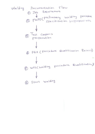
  • 1. ~ - ® Q..S-t Gou~on f .!, F~e..?o.. '1'0.;;'0' J ® ?biR L '"(0 C.Q. d.l.LH e
  • 2. ou) d f-uS t' ')d tlrQ.T<lh>'( " -pG.'tt Cd~ p~,t- 0.w ~ A"rt-iLl2..-1 ~ A'It-I c..~ -·Il ~ 1"(;Ic.. Q... 1 '( fyti c..IL- '-.J ~ t,--cQ...-" p@..t- ~£: ~ A"r'" i CQ... WI1-Id ih 3 I f),(o,L.-iY>3- p'w ~Q..du.y~ , ~dJu , "vVo... d.- ' d CONTENTS G Q...'() Q.tC W Q.. dn~ I.i~ Q.. d.. t no -.j wf>3 W~B. NQ...d.nj SN ".s~
  • 3. A 8. w - 0 '2- ~Q- 5 p a.. LI r-ic..o<-i:: ' o n ?'tfovd.1 flj , VI MQkQ 1" (). YI"f"imu.vY f1c oi Ro.v,qL 0 Va., i £X.k) e..S i' t:-'cJ:: of j 0 i fit n o. ~ 01"1 ~ t)y IVO" Q 'oQ.... V ~ ILJ to fOV RrV1..> _ - bI..Lt'?o'i 0 V ~ 0 " t;<w- ~ W Ps . , , J or ",i Y"lj c..Ot.~bQ..
  • 4. Pf R r 0 P-. N At.i L E= 8 ucd '~ ""'j --t-h Q.. :::0 OL"3 ,- Vo..'Y IOLb' Q.. "(,o....s,ut-t,, ()f Y ~.,u '(' ILd Q 0 1'-) 1.-'1. r '} C 1-'1 Tl Of! W he LV I' II ~ - , Q J Ot r. cI- tt-,/I2., b~-bh' ''j' Gvnd ND'E :;;'I:l ofFo.-t..-t 'Iv, e.... 'V QC-kC!<Y' e.o, ) ~"r 0 pc;. ¥ ;j 0 - tv.,,_ ~ 0 ,'('t!, t 0 Q. y t--.a.n ~ 'fY' r Q ,,,...t )
  • 5. I~ g .;'4.k 1tr,.,,-- 6l. &t - 0 b 0 ..J0. v, ;. '"Lo..{. , 'i) ", t:Xc,, - o6. ? ,ccc Ju.'r ~ NDT I O~ WI , ¥-€. Su.~rOl4>- lAb ~'" . OJ ,
  • 6. .D ~ r T N I T I O ! f !::, ~ IV CI ,' c '-, v t--, Q -'- /'- - OIW ..- 0 I ' 2 W Q.. d 'S) <L - Q....ck ~ . ~ Q..... d.,> c....c"" bi VI u.k Q:1 "r0 l Y li-Q_ t ; OvY J-o,.¥" d ~ ¥:) .__ I?J<lOd ~~~ ~ ------lt
  • 7. wS '-....1)1 N &1 ew- i2...1 A RTICu= - L P DbI T loN $: G tv1 QaJS Butt wQ..J NtD<.n.':. f'ict wold +6tC~w- 4bl-.3Cd) ----- CfE) r-----rl::........---,----. _---'----"-4 rc-(IS(W ...4 bl5(..:1) C...PD) ;--- -.r-------;r Gr C blw "'4bl-3Gar-___ (P A) ~W-2...2. PlPE POSTrIoNS: _ (j 6 I 6 ~ ~ R)t~Q...d &![~W - 4b-4L/lD /
  • 8. SNo I 3 ~ 5 10 T 1)1 A-N D N j)"lf (5(vJ-I5"O ~w- IbO I3.vJ - t1-0 ~w -~O 8.w - 'i12.. 6vJ -g-~ (5( AI - g- it 6>w - Cf 0 B,AI-'1I· ~V'J-92- TEN Sl:. 0 1'1 T t:- .s, _________________.-;» EX. vJ - 5 3 C51IJ'IDED- '6~lD - I;-.sTS______________;>QvJ-Ib3 LM PACT TE- ST _________________?'5+' 'E:c..'-ll"-:LC.IH:rol ~'"I LLf:T_ WE L}) TEST 1-l2.I'c...TtJQ..c TE-ST M ~ C-.RO f XAVVl"LNI'l-TIOIJ - PI<.0 C J;J)JRIE .s?~ c..1 'J)fN ---7 (8 VJ - I If 2) M 1'1 eRO t:: )I. FtYV1JNfTT']:oi') - fSR Z-o<.Ml'I-rk./? Sl'EC.t:VV1t?N > (tx vJ -9" 4- OT-T E R T'E- f:,T K0 ~' D.5'C.f~,,'c. V I~o SOr,I' c.. Ex""WI ; Y cvt-I' 0., . ---------->-'>; afi _ '1 ~ . 2- E 1-. '" yY) i Y>Dv-I' O .. . > 6(w _ q, . 2.·3 V'1. SJ ALE: X'A-vvllN". T I oN ------------>~ aAI - ct 4 ~II!XJTJ) PFI'JETRA-I'lT F)(AM'TNAT.IO N > l0vJ ·-I<1S'· L°2.
  • 9. M£C.HI'NJC.AL T£-ST 8. 11 ., 5" 0 'T RAN 5 v f RS E T E. N S1: L E T [;-ST S ' 'To ' - Shvw -n.12.. Sh~-h--. b~ n,.Q.... JOin,. 'RL 1)cc..s ij , u'T S::i> Loa J CSA <b< w - 5:3 AC-Lt; PTFlNC.E ,..,-. ~ tL- - 0. '"- j:l.?-P~ oo.J S, Q...m'o nAyI2A (,0 No t PQ..ow 1--.Q.. ::,ClL.',e. Vuo. TQY.'>"e,. s,h-~-t" ~) A :-~t 9 1. D~ "Ir.~ Bo<'se. /v',uo,} TQ.j'!:'( k ASM EO -I X "av6Q. 6i IV -422- ASME -}LA lc.on a.6?ontY'2,J YlCI,-1l."('io. (5w-bO Tu I) 5'clQ.. 3Q...nd Ta-,St :?-) Root b Q.y,d T I2-bt CKCC t T QY ::, i on) (}) f 0.. CAL B"-,-;J T 12.6 t- l to..t.A2.. 'T12..n!;,' 0"')
  • 10. ~:vJ -1-0 1MPAL'l" TE,ST " l"""'n's T~t- A~..s"-S~J r-- Q (1 7 _fL J S tD'X'oo.yd ::> , ' yY) ? CJU.-t- 0 Q{d CR..IT E Rl A J0 P ~u.irtl. 'V1 2.V1 ·f (V ;) ,gPtL c... r:. icc<-l-r'o h . exw-8 O '=' '1 LLFi 'WEL-.D 'TE,ST fX.N -)81.. ~ 2...1' c:.T .J R. 'to TEST~ ( ONL'I wf>Q.) 'T : 6..,ou,) "t"Q. 6(vo-..Li t~ «)~ -', d ,NQ.. J 8,,11-83 MALI?.O E)I,AVVlJNA'Tfoh/ CwP.sJ ~w- e lf tv1'c....12.0 E')t AM:n'Ji'I Tro"r (wP&» L~
  • 11. bI o'w- I G10 oTHER TG,ST5 & :.')(.RM~NA'TroNJ &w - q ,. RA.DT D GtQ.F~ PH.rC t; ,)< A MINAT'IorJ (W pe,) ~-~·i·'2..'2. ~ CYO.C.K & LOV:) LDP ~) lJ>to 2> 'YW,,", IVi0.. ')( -'0'( i '" LILtS' VQ. vd ~) '11 b @$ b- foy l:: 'Y) r t<...,.. r:Q...c):-' ., n I'- bL ~ Ij} j}2- 1: 12..:;- ~ 'is """'" J I :'> &.. k --=f-'J- m "" )1 PI c. c..~tQ..J . R.0 lA Ych..J T"~' c.o...b' 0 '" : 'T..-e.... tQ..t El ~ 2, b',...., lL l2..b,SQ. ..- tv,a,v.-, W ;'~ tt.-. No:::. PI c c..-up totbk. ~'1'o~ w dd rVlIvtG 1 C?) := 0 YY1 "" th.iuc.n ~ !, o VQ."' I ) vY "" t-v 51- lYIYh 'V1 c.. USJv,,-. t'v,ex;t om·<2fj ~ IQ..Y>J p., 0 f I L. t· b. L. J;.J +~2.. _ t j) -::> ~ I}.""VQ.'( y>'<2A.k'.,,, .D 2. -? l ....... 'l'1e"" 17~'o", 'L .L -? L " '') l1.6 t J ' "Y) pc{p>,c.t-<'0 " ¥:: 2- ~ ~ ""'3' .3 1 k ~ +2- Faj 2 1 D1+D2<6mm D1+D2+D3=8>6mm
  • 12. cxw- ~2 ULTRI1~DNU... E1<.AM1NlqTTON L wP&j ~W ...'Q ·2 -3 Acc...C-{J~C>VCQ.. L..1f"ctto...YI'o.. GoLAfO"'~ ~ho. No (Y, 'I'Y' f' ~ j 0 I'n. t: '1......b~.-O~Qh~..tfO': I X - , S-- D4 A 0' ~~~ O' DO t A L<.. )(
  • 13. 2- &w - 4-03 3 ~w - 404- 4- G(w - 4 D5 5 8.w '-4ob b 8u) ·- 4-D1 ':J. Gl. tv " 4 0 g % ~w- 40Q q ~W-4-10 0 eW ,-50 &w - bO 2. 6 i~ .- n - D 3 ~w - 160 J.. 6w - H~ 7" S ~lJ - 23 b txw - &4- 1- fX w- 90 '" @?w-!9. .1. law" "I , .2 It? aw - Cf ),. 11 61."'-' - t9S ARTI CLE iJ E LD'1 fl ("1 .)F T f JOTN,-S 816£ IVIETAL,S ~TL-Lt:R. IvETA LS PO~ l TIOlf,S PRE: Ii EP.T POST WEL.D 4 EAT TR.EATMEN T~ c,., fS ISUSc:..iR..'LC.A L CV AR y- Ci E: Rr.sTT L!:, Tec...H N TeLJ[ TEN £>1 L€ TEST G-t U1::DE.:D - .BE ND 'T E.S'I r-RAC.TURE TE6T..,S M AeRo r-OR PRD c...Ej)JRE ~PEC-ltlllE'NS /VlACJ2.. D f='oR PER~oR1Vlnllc.£ Sf'SC-'l.-M E I'/..<, Ra.J..io-Q---Dph' c... r w C Xo.lY{no.b'c'r U'l b--Q 5cr, I L Exo.'V)'"eU::-,'1!) V V'CB,UR..- E 'f;.A tV1:NRI.~DN r 'oR... WpG LleJliJl.D t'ENE,RA N 'T BXAI'V'lI'J~TrON
  • 14. RU~J1'REJ) HlR~S ~w-4g3 reAR exUl -402- ~vu - 403 exvJ .- A-D4 (B,w - A-cS txw- 4-0b (8w - A07 t9-w - J- oQ- t9vu .- A-og ~w - 4-0 ~w -- SO ~w ·- bO C6< vV - ":tv (0v...' - ~ () 6w-92- ~~ - <13 txw-~1- ~w - ~'1 :J>IT A AND ~w-4-~2- e,w-4D2. l8.uJ- 403 (8.w--4-0 lj- 0...w - A-°S ~uJ- Aob (B.w - 4 0 7- ~vJ-4-og l6I.vU - 4 D<1 ~u) .- A-O T E-ST lW'Y..s)?(x'K. JWP!Q) ~w -4~L~-A /4g,4B '>Q /-~ r& ~Vv- q 9w-~4- ~v.J - q L.-
  • 15. PI l,z I lCLt= -IT ~ vJ [LDfNCl PRO CEDul2f QU A /...I FTC14ILO/- ""I(>JJ; ')d Vo.n'ocb t~ ¥'-/IZl'tY'fl . T DAb 1 ~ -~ - '- -2 S-2 thyt) ~ T%IC2-- 2-'33 - S tv) A W Tovb~- 2S"b - GiTfW ARilCLE - 11 ~'vJ- 30 J tXW - t, OI. ......:"':.I2.V1 t o~ I Q.jt- W '? ~ Q. YQ. ,'<'>to..", cllL-d {;;c ~~Y) do~ e...AI -30 - Z $..v..Q. 'i'~ Q4b'Q '" T~ t:, : ' R~w'YIUv)1l..M t- ~ , -::> wP ~ @Y') ~WpS Vo 'rI' ocb l ~ T0I.b 1,<- '3 S o ~0 .. VVlovt- !:, - ~1/ - 4 ~4A- / fXw - 4~Lj 13
  • 16. S,NO 3 .- 2..52 :;0 :W -'353 8.w -'354 0-.w-3S-~ 0(.-->""-- - 3 5 b evJ--35":f - b ~~ - 432. C. ON TE (ITS 10..,;-etbIC-6. poD c..~ 0...-0 Q. LvJ?5) ts sQY)t1c> V<Ay ,'o.b)e.. O, - W LvJ?G.) SS-SQ.X):;;", Vo-ol'c.bk "11 Q.) Eo f)SQ.)')'bo.) V",-'O,'o..btQ. g A-W lVv'P a) ::.::'SQYI~a. r-Jo..o'ot:,lQ.. t=c.AwLWf>~) ES;'CQ...YIt-,o, Vo..,,<AblQ.. f:,-w &J ~5'>Q.Yb6. Vo.y,·oYo1Q.. 'P It:, vJ CvvPG.J i2. TYO .0 ?- l) D GYO '-"f1' '2J b ~ 'b ~ IL Vv) ~ S f- '" y ~ VI. 0 y: ,'c.cvL-; 0 n '-~ b:..D1N ~) D~ ~00 tz... ~v.a>.l.i ~; c.q..h 0 h '--'-"'L""""I 7.:rrl c;;,)
  • 17. 5-No 'T%~ 6 &v! -4S 8,,~·· 45 . 9"vJ-LSI ·3 ~vJ - t>,..s-~ A (~w - 4'02· Co.) A tQ.'( "OJ:;tl.. ';- f'...lo R AovU·f.i ~'D V C(),ssIFc.~'o'" or: rQHO~ A",o.-j ~ S to.. ?'(D CCLdu o(L t IS. - NAVV'lb Q.1'-") b<l...r.d cA.t ~i ~ .AJ Q...J 'Q.6 t.s WCLJ MQj;-o.. 19uoJj t- " c.o..b'O'l ? E..R~<D R IV AN C. E aVl"lL1.~1: C..-1T1.or...! TI-I1c....KrJG5J -1- "VI r T.s '" Nj) 1::S .s~ :cc.:C MEr.'.s -
  • 18. ID-b~ ~r;.;; - 452· (j, ~w-452...- 3 Qw -.4-52...-4 ~v-I -452...· 5 to..w - 4-5 '2.. . b e'IN-4bD G<w-4 b G,Jl -4-6• Sly,) _ 4-b1 2... <6w -4-)3 6(v-J - Ab ~ (£XV'! - 461·5 S-vJ-t-- '0 · 6 fJ-.w -4bl .+ (9w - t-b' g Qvv-4bl ·9 ~,oo Ie... - W del ~ o..m~'" 3 "'"().,) IXo.."fY) I2ku-T ~ Q.k- _ W Q.. d o...-s :; Nf!:> /'vJPtX. trvlc..k."'~s.j Limit-s OYLJ T e.st S"Q...OM~Vl.s~"<" OvQ.....,(j-S Or RA ?- lC!, Po b1.r r ON~ -?o.btn' o~ Dy wQ..dtJ - GnoOlQ.. WQ..d S t'm..:,ttl'o"1S D~ wQ..~.!:, -r;Q1- we.JJ.t, G.oovL we..<:b ' '0, 9)ovI..~- T~.)t- >o.)lb' o,,", G,OO'l''I<... wQ...1.s In ?I?Q... -Q.oc ,?o.s.i~''''''' f,* W'Q...d.:, iY p'lo...bL -T.u..st- ?O~t-lo'n rc; Q.t- ;.J Q d~ i Y '? ? (L _ " Q.:' I:: 'fooS i tl 'OV S Stud vJ lLcis - T<LS t ?<o s- t-io'n.s St-uJ w !2..clS _ W Q. ~ "'-.'j '? <0 oS i' to' 0 " rJ?G,. - ?<c.:,b O '" Q..Xd 1)OY'IQ.D2.x Lmih::"b'Oy))
  • 19. D ~vJ-4b2. (Xv-.! -4b2. CO) ~V'-i-4b2.· (h» Q.w - 4b2.(.c..) 6(v-J -4'0'2.. 0) 15<1'.1 -41:>2.. l~) QvJ -4k>2. - 2.. ~ 'v'-.i-t- b 2. ~C.o·) (8v0-k b2 3(b) ew -4b2.A (a) ~ W - 4b 2.-Alb) I9w-4 62.. -A (c..) ~w -46 2 40) (fAw -4 b 2..·5 Lo..) G-VI - 4-b'l. 5" c..c.) tXw - Ab2..-S Cd) &.w -4 b 2.S LC2.-) T a...Y'>s, "0 Y' • RQ...d1Ac..e.cl SQ.t.b' 0 n _ .plo.k42.. T<Q..YS'on _'L 'uc..- S~"L IS" ~ "'-0 ~on _ ,lop:.. T C2...Y SIOV - K<WUC-W S Q..W 0 '" A H-o.y~ ~.. Pl'pe. T(LI'S~'" - RM'-AC_:Q.cl SlU..toY' - TU.l"'DI2..J Sr'wYnQ...Y.) TCL.Y1-.S' OV1 - ~v. SQ..t.kiol" _ SY'YCA) j)o..YYlWLo pl~ SidQ.. E,Q.hd y:'o c..e.... O-.n d RdlO t- b Q..hd. b - ',0..'"6 V Q.~ S e.. f'o. C-Q.. OXJ. -R<:>v t- E:, Q..Vd S - L<tl ~ i b-IeLi no.) ~ ', h .t w Q..J.s . Pcx..t--Q.. ? Yo C-Q..o l.l re... In - -Io..t WI2....J::, - ro..h.. _ ~ Q.. 'fD" 'Y'Gn ~ IY' t=";~ W Q...-6..) - pI/I2.. - ? Q...'6"(-0 '(NI 0.1' e-e IY' vJQ.ci ., - , ? '6" ') c...Q... 0,Ye. ~~ '" ?lpl2.. C~I2..Nc..Q. AY",:~S D.lrd -a.,dl>~ S'fwyY)~'" ~ 0'( QI Q.'& e>..j S. C ~ 12....VV i ':0. AY)C>.~ -" :..>! ~o..yd ) Q...~ ~ r M",c... ¥ 0 0 c.cx.-:-to Y <>6 '0 "Q.'(~ t>? 12.. 16Q.Y'0 ~ Ii' Q.. c...i m QX - we..: 0 YI2... )o.,~ ? <>-tu... 'b o.Y d S rCQ. c.. «1 Q.X) .:" w "-0 Q v a..Y ~ I( cJ-t,. M "'.::" 0 ( 't- 0. ... dV oh1 , L h Q m "cov1 S -t' I2...U ' rY) "-"" ~G' 'V-J12-d fQ/o..'(~
  • 20. Gw-4b3·1(0-) (9 vJ- 4b3-ILb) (1;( rJ • -4b3 C.c.) eV'J- 4- b~' C) EXvv' . 4bo·2.- Co-) ~ 'vj - .; I?3 2-Cleh) 1'Xv0 - 4 ,Gk,. 7> ~ ~~ - LQ..s,.:, ~ <1 YV'I'<V 'v( ? 61 R 1fl1, t- ?IIW- LC.a.h'o", ~i oJ::e. _ M "..-Q... ~(lA,V a, 'Y'I VY ~<. f'R C '~-- pIa.v-<- LcQp./:-to" . Picvbe. _ Lv"'3;t~'Y'lo. f y-o c..cdv.",,- ~' (=-:QoJ,.'0'" "'-0 ~ P 'Q... 0e.. L0 ~-v Y" L-0 c.cJ::t'<0 Y'I • ? a.ke.. LIU-:S -tv,""" '1 Yy) IV th ~<- ?11-y Y:o '( VY GU ~ (fX u. ~'- c.q.,t--,''"'" Ro", t- (-0.. tA2. b 12-1' J T ~ 1: Sf ,,,.L;m """ L-O o:>.-h' "V' . ?~ ::::.. o,WYV "'~ flO..'<'-o'('''IOvr'c.-.e. C8...~'I-'~'o... S 1c t2... 0 .a..", J S?Q.. cJ '(Y) Q...Y' U-b :. S f ~ m '"-" Lo c.o.h'0" ~ ~ - LOV'3b.lcLi ~ ?0- 't '-0'(" yY') a..fI CA:2.. 8.~' fl co.lo'.?., 0.6+ 3?<2-u<Y<V" La C.cJ-IO.. . , M a.c..r0 3rI:U:..:"", a..>' Fo.,... f I P~ ~ V Id<1.J 'b!2XJ
  • 21. 5No 1 2-- 3 A;- 5 e;:xw- 4'D 2- ew --40 3 8.'1-- A; o.q (!xw -- 4D5 (QvJ -- 40 b ExW -- 40 ~ Qw -- II 09 exw -- 4 10 .~ ELP'l N G, Jo1. '".1 S J) ~TA- Ro.~Q;1rQXCI2..(Ace... .s+J ______---------~7 S?Ec.l~1 CRTIO'I /'J)'KAvJI.NJ BAS't: rv' t:T 1'1 L- S ___________-kAoS N G-11i., l.0.-- 6<w--422... ~----------_~ ' /ASI'V Go -- i.C- ,J.'1--._- G.vJ --43 2 ~l....L El<- Mf-TP!LS PvS'L- ,10NS C f?L-A' r= JF'1~S)- l?R~ - £p.," _-------,)03- -- ~w -- 4 bl 3 /rrxv-J--4b1 ·LJ.. _ _ _ _ -----------JJ~PW-- ~ 1'111 AI'' Q.1'6,< -- R '2>31-3 _>1o-b1o... 33°' . VW~--------------------1F~~ 3~ .~I~~?=- = ~ ~ ~~ 3 ~ .; 4~1~ '{ill--P"d-- -? uC--S -51:/VtlA --32 ~32:, --;>To.bo... 331·- Gr RS_________________L: 10 31 . I --7 Tctb t2- 3 2... ~c.. '7 SI=-R-53z-
  • 22. ASME BPVC.IX-Z015 (15) FORM aW-482 SUGGESTED FORMAT FOR WELDING PROCEOURE SPECIFICATIONS (WPS) (See OW-200.1. Section IX. ASME Boiler and Pressure Vessel Code) Organization Name 8y Welding Procedure Specification No. Date Supporting PQR No.(s) Revision No. Date Welding Process(es) Type(s) (Autom. tic. M. ny.... Mac"'ne. o r S~mi·A"tom.'io) JOINTS (QW-402) Details Joint Design Root Spacing Backing: y" No Backing Material (Type) IRcfur to both bading.no <I'.,M'S) 0 Metal o Nonfusing Metal 0 Nonmetallic o Other Sketches. Production Draw ings, Weld Symbols, or Written Description should show the general arrangement otthe parts to be welded. Where applicable, the details of weld groove may be specified. Sketches may be attached to illustrate joint design, weld layers. 3I"Id bead sequence le.g., for notch toughness procedures, tor multiple process procedures, etc.)} · eASE METALS (OW-.403) f:l "" - 4-2-2- P-No Group No. toP-No. Group No. OR NQ"M IL I£.i Y-~~ A t,IVI r:i 1I A Speciflcalion and type/grade or UNS Number to Specification and type/grade or UNS Number OR llSMr;; -Ir{j Chem. Analysis and Mech. Prop. to Chern. Ana lysis and Mech. Prop. Thickness Range: =fo.blQ.. 61w-A51 ' "TunQ eW-A St- 3 Base Metal: Groove Fillel Maximum Pass Thickness ~ 1/2 in. (13mm) (Yes) ___ (No) ___ Olher "'FILLER METALS (QW·404) ,,~V/"- ~~l'0 2 Spoc. No. (SFA) AWS NO. (Class) -ornwo ~:Li7:? F-No. A·No. TlLlolo _ "'W - AA-" Size of Filler Metals Filler Metal Product Form Supplomental Filler Metal Weld Metal Deposited Thickr.ess: l-r,.. ,, 112- _ Cl'hl _-4- c::.1• I Groove Fillel Electrode·Flux (Class) FluXType Flux Trade Name Consumable Insert Other ~Each base metal·fille r metal combination should be speCified individually. (07/15) 307 ~ n 2 o - r
  • 23. n 0 ~ ~ " ". ~ " A.SME BPVC.IX-201$ ~ B ~ ~ B ~ m ~ FORM QW-482 (Backl WPS No. Rev. ~ n -- B " • B ~ ~ POSITIONS IOW-405J POSTWELD HEAT TREATMENT (OW-407) ~..3 '~3 -;>To-b 12.. :'>2 Posilion(5) nf Groove Temperalum Rang" Welding ProgresSIon Up OO~ Tlnlll Range ~lB I !:!'":1. 0 tl CS- 5 b 0 C Position!,) Of Fillet Other U 't B - "02 ;!. < B " • ~ ~ ~ '" ~ 0 Other GAS (OW-408) S~ 1' -S;,~,~coY:}.;:EO·TIc..) PREHEAT (QW-406) B 3'l ..3 OT«.bI<- 330-' I Pr eheat Temperature, Minimum a Gas(es) (MiJ(ture) Flow Rate Intarpass Temperature, M aximim t.. ~Wt;.~_J) 1.. . Preheat Maintenance tv Q'" Mt1" ::J Ap ~O Shielding Olher Trailing " 0 '" 0 (Continuous or special heating, where applicable, should be specified) Backing Other cr ~ ELECTRICAL CHARACTERISTICS IQW-4(9) ~ 0 iii 0 " ~ ~. B Filler Metal Olher (e.g . Remarks. Com- '" ". ~ ~ n Current Wl/e Fe&<! Energv Dr Travel menrs, Hot Wire Wetd Classifi- TVpe and Amps Speed Power Volts Speed AddIt Ion. TechnIque, Pass(es) Process cation Diameter Polarity (Range) (Range) (Range) (Range) (Range) TOlch Angle, etc.} 5' ~ f ;; n " Ampg and VOlts. or power or energy range, should be speCIfied for each electrode $i~e, position, and thickness, etc. ~ " B :! Pul$ing Current Heat 'nput Ima)!:.) n 0 e Tung!len £Ieelrode $ '1.e and Type aJ;,YV1 ( -1T C S!;~ - S ' IL .""'.. , ......... 2% Thoriol.... etc.1 ~ Mode of Metal Transfer for GMAW (FCAW) tSp••v A ,C. SI>ott C"""'~"" ~ eteJ • ~ h9r n 0 ~ TECHNIQUE !QW-4101 ~ ~ 0 2- String or Weave Bead Orifice, Nozzle, or Gas Cup Size 0 m ~ Initial and Interpass Cloaning (Brushing, Grinding, etc.) . - B ~ Method of BaCk Gouging 0 OscillatIon " N 0 Cont ~ct Tube to Work DIStance MultIple or Single Pass (Per Side) 'i' 0 ~ MultIple or Single £Iectrockls Electrode SpacIng Peening ~ 0 ~her ~ ~ ~ W ~ '" ~ 0 (<l7/15) 0 cr ~ m ~ " 0 " N B ~ C • m " ~ 0 ~ m " m iC ~ " 308 0 ~ z 0 ~ r
  • 24. Table QW/QB-422 Ferrous/Nonferrous P-Numbers Grouping of Base Metals for Qualification (Cont'd) Spec. No. Type or Grade UNS No. Minimum Specified Tensile, ksi (MPa) Welding Brazing ISO 15608 Group Nominal Composition Product Form P‐No. Group No. P‐No. Ferrous (Cont'd) A/SA–508 4N, Cl. 3 K22375 90 (620) 3 3 102 3.1 3.5Ni–1.75Cr–0.5Mo–V Forgings A/SA–508 3VCb K31390 85 (585) 5C 1 102 6.2 3Cr–1Mo–0.25V–Cb–Ca Forgings A/SA–508 3V K31830 85 (585) 5C 1 102 6.2 3Cr–1Mo–V–Ti–B Forgings A/SA–508 5, Cl. 1 K42365 105 (725) 11A 5 102 3.1 3.5Ni–1.75Cr–0.5Mo–V Forgings A/SA–508 5, Cl. 2 K42365 115 (795) 11B 10 102 3.1 3.5Ni–1.75Cr–0.5Mo–V Forgings A/SA–513 1008 G10080 42 (290) 1 1 101 1.1 C Tube A/SA–513 1010 G10100 45 (310) 1 1 101 1.1 C Tube A/SA–513 1015 G10150 48 (330) 1 1 101 1.1 C Tube A513 1015 CW G10150 … 1 1 101 1.1 C Tube A513 1020 CW G10200 … 1 2 101 1.1 C Tube A513 1025 CW G10250 … 1 2 101 1.2 C Tube A513 1026 CW G10260 … 1 3 101 11.1 C Tube A514 Q … 100 (690) 11B 9 102 3.1 1.3Ni–1.3Cr–0.5Mo–V Plate > 21 /2 in. – 6 in. (64 mm – 152 mm), incl. A514 Q … 110 (760) 11B 9 102 3.1 1.3Ni–1.3Cr–0.5Mo–V Plate, 21 /2 in. (64 mm) max. A514 F K11576 110 (760) 11B 3 101 3.1 0.75Ni–0.5Cr–0.5Mo–V Plate, 21 /2 in. (64 mm) max. A514 B K11630 110 (760) 11B 4 101 3.1 0.5Cr–0.2Mo–V Plate, 11 /4 in. (32 mm) max. A514 A K11856 110 (760) 11B 1 101 3.1 0.5Cr–0.25Mo–Si Plate, 11 /4 in. (32 mm) max. A514 E K21604 100 (690) 11B 2 102 3.1 1.75Cr–0.5Mo–Cu Plate > 21 /2 in. – 6 in. (64 mm – 152 mm), incl. A514 E K21604 110 (760) 11B 2 102 3.1 1.75Cr–0.5Mo–Cu Plate, 21 /2 in. (64 mm) max. A514 P K21650 100 (690) 11B 8 102 3.1 1.25Ni–1Cr–0.5Mo Plate > 21 /2 in. – 6 in. (64 mm – 152 mm), incl. A514 P K21650 110 (760) 11B 8 102 3.1 1.25Ni–1Cr–0.5Mo Plate, 21 /2 in. (64 mm) max. A/SA–515 60 … 60 (415) 1 1 101 11.1 C–Si Plate > 1 in. (25 mm) A/SA–515 60 K02401 60 (415) 1 1 101 1.1 C Plate ≤ 1 in. (25 mm) A/SA–515 65 K02800 65 (450) 1 1 101 11.1 C–Si Plate A/SA–515 70 K03101 70 (485) 1 2 101 11.1 C–Si Plate A/SA–516 55 K01800 55 (380) 1 1 101 1.1 C–Si Plate A/SA–516 60 K02100 60 (415) 1 1 101 1.1 C–Mn–Si Plate A/SA–516 65 K02403 65 (450) 1 1 101 1.1 C–Mn–Si Plate A/SA–516 70 K02700 70 (485) 1 2 101 11.1 C–Mn–Si Plate A/SA–517 F K11576 115 (795) 11B 3 101 3.1 0.75Ni–0.5Cr–0.5Mo–V Plate ≤ 21 /2 in. (64 mm) 117 ASME BPVC.IX-2015 Copyrighted material licensed to University of Toronto by Thomson Scientific, Inc. (www.techstreet.com). This copy downloaded on 2015-07-13 07:36:37 -0
  • 25. ASME BPVC.II.A-2015 SA-516/SA-516M 930 TABLE 1 CHEMICAL REQUIREMENTS Composition, % Grade 60 Grade 65 Grade 70 Grade 55 [Grade 415] [Grade [Grade 485] Elements [Grade 380] 450] Carbon, max(A), (B) : 1 ⁄2 in. [12.5 mm] and under 0.18 0.21 0.24 0.27 Over 1 ⁄2 in. to 2 in. [12.5 to 50 mm], incl 0.20 0.23 0.26 0.28 Over 2 in. to 4 in. [50 to 100 mm], incl 0.22 0.25 0.28 0.30 Over 4 to 8 in. [100 to 200 mm], incl 0.24 0.27 0.29 0.31 Over 8 in. [200 mm] 0.26 0.27 0.29 0.31 Manganese(B) : 1 ⁄2 in. [12.5] and under: Heat analysis 0.60–0.90 0.60–0.90 (C) 0.85–1.20 0.85–1.20 Product analysis 0.55–0.98 0.55–0.98 (C) 0.79–1.30 0.79–1.30 Over 1 ⁄2 in. [12.5 mm]: Heat analysis 0.60–1.20 0.85–1.20 0.85–1.20 0.85–1.20 Product analysis 0.55–1.30 0.79–1.30 0.79–1.30 0.79–1.30 Phosphorus, max(A) 0.035 0.035 0.035 0.035 Sulfur, max(A) 0.035 0.035 0.035 0.035 Silicon: Heat analysis 0.15–0.40 0.15–0.40 0.15–0.40 0.15–0.40 Product analysis 0.13–0.45 0.13–0.45 0.13–0.45 0.13–0.45 NOTES: (A) Applies to both heat and product analyses. (B) For each reduction of 0.01 percentage point below the specified maximum for carbon, an increase of 0.06 percentage point above the specified maximum for manganese is permitted, up to a maximum of 1.50% by heat analysis and 1.60% by product analysis. (C) Grade 60 plates 1 ⁄2 in. [12.5 mm] and under in thickness may have 0.85–1.20% manganese on heat analysis, and 0.79–1.30% manganese on product analysis. TABLE 2 TENSILE REQUIREMENTS Grade 55 [380] 60 [415] 65 [450] 70 [485] Tensile strength, ksi [MPa] 55–75 [380–515] 60–80 [415–550] 65–85 [450–585] 70–90 [485–620] Yield strength, min, ksi [MPa](A) 30 [205] 32 [220] 35 [240] 38 [260] Elongation in 8 in. [200 mm], min, % (B) 23 21 19 17 Elongation in 2 in. [50 mm], min, % (B) 27 25 23 21 NOTES: (A) Determined by either the 0.2% offset method or the 0.5% extension-under-load method. (B) See Specification A 20/A 20M for elongation adjustment. Copyrighted material licensed to University of Toronto by Thomson Scientific, Inc. (www.techstreet.com). This copy downloaded on 2015-07-13 07:13:01 -0500 by authorized user logan ahlstrom. No fu QW-403 QW-403
  • 26. ð15Þ that was used in the qualification test without considera- tion of the compatibility of the base and filler metals from the standpoint of metallurgical properties, postweld heat treatment design and service requirements, and mechan- ical properties. Table QW-432 F-Numbers Grouping of Electrodes and Welding Rods for Qualification F‐No. ASME Specification AWS Classification UNS No. Steel and Steel Alloys 1 SFA-5.1 EXX20 ... 1 SFA-5.1 EXX22 ... 1 SFA-5.1 EXX24 ... 1 SFA-5.1 EXX27 ... 1 SFA-5.1 EXX28 ... 1 SFA-5.4 EXXX(X)‐26 ... 1 SFA-5.5 EXX20‐X ... 1 SFA-5.5 EXX27‐X ... 2 SFA-5.1 EXX12 ... 2 SFA-5.1 EXX13 ... 2 SFA-5.1 EXX14 ... 2 SFA-5.1 EXX19 ... 2 SFA-5.5 E(X)XX13‐X ... 3 SFA-5.1 EXX10 ... 3 SFA-5.1 EXX11 ... 3 SFA-5.5 E(X)XX10‐X ... 3 SFA-5.5 E(X)XX11‐X ... 4 SFA-5.1 EXX15 ... 4 SFA-5.1 EXX16 ... 4 SFA-5.1 EXX18 ... 4 SFA-5.1 EXX18M ... 4 SFA-5.1 EXX48 ... 4 SFA-5.4 other than austenitic and duplex EXXX(X)‐15 ... 4 SFA-5.4 other than austenitic and duplex EXXX(X)‐16 ... 4 SFA-5.4 other than austenitic and duplex EXXX(X)‐17 ... 4 SFA-5.5 E(X)XX15‐X ... 4 SFA-5.5 E(X)XX16‐X ... 4 SFA-5.5 E(X)XX18‐X ... 4 SFA-5.5 E(X)XX18M ... 4 SFA-5.5 E(X)XX18M1 ... 4 SFA-5.5 E(X)XX45 ... 5 SFA-5.4 austenitic and duplex EXXX(X)‐15 ... 5 SFA-5.4 austenitic and duplex EXXX(X)‐16 ... 5 SFA-5.4 austenitic and duplex EXXX(X)‐17 ... 6 SFA-5.2 All classifications ... 6 SFA-5.9 All classifications ... 6 SFA-5.17 All classifications ... 6 SFA-5.18 All classifications ... 6 SFA-5.20 All classifications ... 6 SFA-5.22 All classifications ... 6 SFA-5.23 All classifications ... 6 SFA-5.25 All classifications ... 6 SFA-5.26 All classifications ... 6 SFA-5.28 All classifications ... 6 SFA-5.29 All classifications ... 162 ASME BPVC.IX-2015 Copyrighted material licensed to University of Toronto by Thomson Scientific, Inc. (www.techstreet.com). This copy downloaded on 2015-07-13 07:36:37 -0500 by authorized user logan ahlstrom. No fu
  • 27. ASME BPVC.II.C-2015 SFA-5.18/SFA-5.18M 481 TABLE 1 CHEMICAL COMPOSITION REQUIREMENTS FOR SOLID ELECTRODES AND RODS AWS Classificationb Weight Percenta UNSc A5.18 A5.18M Number C Mn Si P S Ni Cr Mo V Cud Ti Zr Al 0.90 0.40 0.05 0.02 0.05 ER70S-2 ER48S-2 K10726 0.07 to to 0.025 0.035 0.15 0.15 0.15 0.03 0.50 to to to — — — 1.40 0.70 — — — — — — — 0.15 0.12 0.15 0.06 0.90 0.45 ER70S-3 ER48S-3 K11022 to to to 0.025 0.035 0.15 0.15 0.15 0.03 0.50 — — — — — 0.15 1.40 0.75 0.06 1.00 0.65 ER70S-4 ER48S-4 K11132 to to to 0.025 0.035 0.15 0.15 0.15 0.03 0.50 — — — — — 0.15 1.50 0.85 0.06 1.40 0.80 ER70S-6 ER48S-6 K11140 to to to 0.025 0.035 0.15 0.15 0.15 0.03 0.50 — — — — — 0.15 1.85 1.15 0.07 1.50 0.50 ER70S-7 ER48S-7 K11125 to to to 0.025 0.035 0.15 0.15 0.15 0.03 0.50 — — — — — 0.15 2.00e 0.80 ER70S-G ER48S-G — Not Specifiedf NOTES: a. Single values are maximum. b. The letter “N” as a suffix to a classification indicates that the weld metal is intended for the corc belt region of nuclear reactor vessels, as described in the Annex to the specification. This suffix changes the limits on the phosphorus and copper as follows: P p0.012% maximum Cup0.08% maximum c. SAE HS-1086/ASTM DS-56, Metals & Alloys in the Unified Numbering System. d. Copper due to any coating on the electrode or rod plus the copper content of the filler metal itself, shall not exceed the stated 0.50% max. e. In this classification, the maximum Mn may exceed 2.0%. If it does, the maximum C must be reduced 0.01% for each 0.05% increase in Mn or part thereof. f. Chemical requirements are not specified but there shall be no intentional addition of Ni, Cr, Mo, or V. Composition shall be reported. Requirements are those agreed to by the purchaser and the supplier. 2.4 ISO Specification. 4 The following ISO standard is referenced in the mandatory sections of this document. (a) ISO 544, Welding consumables—Technical delivery conditions for welding filler metals—Type of product, dimensions, tolerances and markings 3. Classification 3.1 The solid electrodes (and rods) covered by the A5.18 specification utilize a classification system based upon U.S. Customary Units and are classified according to the chemical composition of the electrode, as specified in Table 1, and the as-welded mechanical properties of the weld metal, as specified in Tables 3 and 4. The composite stranded electrodes and composite metal cored electrodes covered by this specification also utilize a classification system based upon U.S. Customary Units and are classified according to the chemical composition and mechanical 4 ISO standards are published by the International Organization for Standardization, 1 rue de Varembé, Case postale 56, CH-1211 Geneva 20, Switzerland. properties of the weld metal as specified in Tables 2, 3, and 4 and the shielding gas employed. 3.1M The solid electrodes (and rods) covered by the A5.18M specification utilize a classification system based upon the International System of Units (SI) and are classi- fied according to the chemical composition of the electrode, as specified in Table 1, and the mechanical properties of the weld metal, as specified in Tables 3 and 4. The composite stranded electrodes and composite metal cored electrodes covered by this specification also utilize a classification system based upon the International System of Units (SI) and are classified according to the chemical composition and mechanical properties of the weld metal as specified in Tables 2, 3, and 4 and the shielding gas employed. 3.2 Electrodes and rods classified under one classifica- tion shall not be classified under any other classification in this specification, except that composite stranded elec- trodes or composite metal cored electrodes classified as E70C-XC [E48C-XC] may also be classified as E70C-XM [E48C-XM], or vice versa, provided the product meets the requirements of both classifications. Copyrighted material licensed to University of Toronto by Thomson Scientific, Inc. (www.techstreet.com). This copy downloaded on 2015-07-13 07:14:57 -0500 by authorized user logan ahlstrom. No fu SPECIFICATION FOR CARBON STEEL ELECTRODES AND RODS FOR GAS SHIELDED ARC WELDING
  • 28. ASME BPVC.II.C-2015 SFA-5.18/SFA-5.18M 482 TABLE 2 CHEMICAL COMPOSITION REQUIREMENTS FOR WELD METAL FROM COMPOSITE ELECTRODES AWS Classificationa Weight Percentd UNS A5.18 A5.18M Numberb Shielding Gasc C Mn Si S P Nic Cre Moe Vc Cu Multiple Pass Classifications E70C-3X E48C-3X W07703 75-80% Ar/Balance 0.12 1.75 0.90 0.03 0.03 0.50 0.20 0.30 0.08 0.50 CO2 or CO2 E70C-6X E48C-6X W07706 75-80% Ar/Balance 0.12 1.75 0.90 0.03 0.03 0.50 0.20 0.30 0.08 0.50 CO2 or CO2 E70C-G(X) E48C-G(X) — f Not Specifiedg Single Pass Classifications E70C-GS(X) E48C-GS(X) — f Not Specifiedh NOTES: a. The final X shown in the classification represents a “C” or “M” which corresponds to the shielding gas with which the electrode is classified. The use of “C” designates 100% CO2 shielding (AWS A5.32 Class SG-C). “M” designates 75-80% Ar/balance CO2 (AWS A5.32 Class SG-AC-Y, where Y is 20 to 25). For E70C-G [E48C-G] and E70C-GS [E48C-GS], the final “C” or “M” may be omitted if these gases are not used for classification. b. SAE HS-1086/ASTM DS-56, Metals & Alloys in the Unified Numbering System. c. Use of a shielding gas other than that specified will result in different weld metal composition. d. Single values are maximums. e. The sum of Ni, Cr, Mo, and V shall not exceed 0.50%. f. Shielding gas shall be as agreed upon between purchaser and supplier, unless designated by the C or M suffix. g. Composition shall be reported; the requirements are those agreed to between purchaser and supplier. h. The composition of weld metal from this classification is not specified since electrodes of this classification are intended only for single pass welds. Dilution, in such welds, usually is quite high. TABLE 3 TENSION TEST REQUIREMENTS (AS WELDED) Tensile Strength Yield Strengthb Elongationb AWS Classificationa (minimum) (minimum) Percent A5.18 A5.18M Shielding Gas psi MPa psi MPa (minimum) ER70S-2 ER48S-2 ER70S-3 ER48S-3 ER70S-4 ER48S-4 CO2 c 70 000 480 58 000 400 22 ER70S-6 ER48S-6 ER70S-7 ER48S-7 ER70S-G ER48S-G d 70 000 480 58 000 400 22 E70C-3X E48C-3X 75-80% Ar/balance CO2 E70C-6X E48C-6X or CO2 70 000 480 58 000 400 22 E70C-G(X) E48C-G(X) d 70 000 480 58 000 400 22 E70C-GS(X) E48C-GS(X) d 70 000 480 Not Specified Not Specified NOTES: a. The final X shown in the classification represents a “C” or “M” which corresponds to the shielding gas with which the electrode is classified. The use of “C” designates 100% CO2 shielding (AWS A5.32 Class SG-C); “M” designates 75-80% Ar/balance CO2 (AWS A5.32 Class, SG-AC-Y, where Y is 20 of 25). For E70C-G [E48C-G] and E70C-GS [E48C-GS], the final “C” or “M” may be omitted. b. Yield strength at 0.2% offset and elongation in 2 in. [50 mm] gage length (or 1.4 in. [36 mm] gage length for the 0.350 in. [9.0 mm] tensile specimen recommended in A4.2 for the optional in A4.2 for the optional acceptance test using gas tungsten arc). c. CO2 p carbon dioxide shielding gas (AWS A5.32 Class SG-C). The use of CO2 for classification purposes shall not be construed to preclude the use of Ar/CO2 (AWS A5.32 Class SG-AC-Y) or Ar/O2 (AWS A5.32 Class SG-AO-X) shielding gas mixtures. A filler metal tested with gas blends, such as Ar/O2, or Ar/CO2 may result in weld metal having higher strength and lower elongation. Testing with 100% argon shielding (AWS A5.32 Class SG-A) is required when classification testing is based on GTAW only (see A4.2 in Annex A). d. Shielding gas shall be as agreed to between purchaser and supplier, unless designated by the C or M suffix. Copyrighted material licensed to University of Toronto by Thomson Scientific, Inc. (www.techstreet.com). This copy downloaded on 2015-07-13 07:14:57 -0500 by authorized user logan ahlstrom. No fu
  • 29. ASME BPVC.II.C-2015 SFA-5.18/SFA-5.18M 501 (AWS A5.32 Class SG-AC-Y) as the shielding gas or with CO2 (AWS A5.32 Class SG-C) alone. The penetration of such welds is greater with CO2 than it is with argon-CO2 mixtures. Mixtures of 50 to 80% argon with CO2 remainder (AWS A5.32 Class SG-AC-Y, where Y is 20 to 50) can be advantageous for thin material. However shielding gas mixtures of 50% to 70% argon with CO2 remainder (AWS A5.32 Class SG-AC-Y, where Y is 30 to 50) are unstable in the gaseous state and must be mixed from single gas components immediately prior to use. They provide low penetration, higher short circuiting rates, and lower mini- mum currents and voltages than CO2 alone does. This can be an advantage in welding thin plate. A7. Description and Intended Use of Electrodes and Rods A7.1 ER70S-2 [ER48S-2]. Electrodes and rods of the ER70S-2 [ER48S-2] classification are primarily used for single-pass welding of killed, semi-killed, and rimmed steels, but may be used for some multipass applications. Because of the added deoxidants, these filler metals can be used for welding steels that have a rusty or dirty surface, with a possible sacrifice of weld quality depending on the condition of the surface. ER70S-2 [ER48S-2] filler metals are used extensively to produce high quality, high tough- ness welds with the GTAW process. These filler metals are also well suited for use in single side, melt through welding without a protective root shielding gas on the backside of the joint. Typical specifications for these steels are ASTM A 36, A 285-C, A 515-55, and A 516-70, which have UNS numbers K02600, K02801, K02001, and K02700, respectively. A7.2 ER70S-3 [ER48S-3]. Electrodes and rods of the ER70S-3 [ER48S-3] classification are intended for welding single-pass and multi-pass welds. Typical base metal speci- fications are often the same as those for the ER70S-2 [ER48S-2] classification. Electrodes of the ER70S-3 [ER48S-3] classification are the most widely used of the GMAW electrodes classified under this specification. A7.3 ER70S-4 [ER48S-4]. Electrodes and rods of the ER70S-4 [ER48S-4] classification are intended for welding steel where conditions require more deoxidation than is provided by the ER70S-3 [ER48S-3] filler metal. Typical base metal specifications are often the same as those for the ER70S-2 [ER48S-2] classification. This classification does not require impact testing. A7.4 ER70S-6 [ER48S-6]. Electrodes and rods of the ER70S-6 [ER48S-6] classification are intended for both single- and multiple-pass welding. They are especially suited for sheet metal applications, where smooth weld beads are desired, and structural and plate steels that have moderate amounts of rust or mill scale. These electrodes permit the use of higher current ranges with either CO2 (AWS A5.32 Class SG-C) shielding gas or with mixtures of argon and oxygen (AWS A5.32 Class SG-AO-X) or argon and carbon dioxide (AWS A5.32 Class SG-AC-Y). However, these electrodes do require a higher level of oxidation than the previously described electrodes when using either binary or ternary argon shielding gas mixtures per the AWS A5.32 specification. Typical base metal speci- fications are often the same as those for the ER70S-2 [ER48S-2] classification. A7.5 ER70S-7 [ER48S-7]. Electrodes and rods of the ER70S-7 [ER48S-7] classification are intended for single- and multiple-pass welding. They may permit welding with higher travel speeds compared with ER70S-3 filler metals. They also provide somewhat better wetting action and bead appearance when compared with those filler metals. These electrodes permit the use of higher current ranges with either CO2 (AWS A5.32 Class SG-C) shielding gas or with mixtures of argon and oxygen (AWS A5.32 Class SG- AO-X) or argon and carbon dioxide (AWS A5.32 Class SG-AC-Y). However, these electrodes do require a higher level of oxidation (more CO2 or O2) like the previously described electrode when using either binary or ternary argon shielding gas mixtures per the AWS A5.32 specifi- cation. Typical base metal specifications are often the same as those for the ER70S-2 [ER48S-2] classifications. A7.6 ER70S-G [ER48S-G] and E70C-G [E48C-G]. Electrodes and rods of the ER70S-G [ER48S-G] and elec- trodes of the E70C-G [E48C-G] classifications are those filler metals not included in the preceding classes and for which only certain mechanical property requirements are specified. Electrodes of the E70C-G [E48C-G] classifica- tion may be classified with either CO2 (AWS A5.32 Class SG-C) or 75–80% Ar/balance CO2 (AWS A5.32 Class SG-AC-Y, where Y is 20 to 25) as shown by the “C” or “M” suffix. Absence of the C or M suffix means that the shielding gas used for testing was not one of the above AWS classes and the electrode manufacturer should be consulted for the recommended shielding gas to be used. The electrodes are intended for both single-and multiple- pass applications. The filler metal supplier should be con- sulted for the composition, properties, characteristics, and intended use of these classifications (see A2.3 for further information). A7.7 E70C-GS [E48C-GS]. Electrodes of the E70C- GS [E48C-GS] classification are composite stranded or metal cored electrodes intended for only single-pass appli- cations. The electrodes may be classified with either CO2 (AWS A5.32 Class SG-C) or 75–80% Ar/balance CO2 (AWS A5.32 Class SG-AC-Y, where Y is 20 to 25) as shown by the “C” or “M” suffix. Absence of the C or M suffix means that the shielding gas used for testing was not one of the above AWS classes and the electrode manu- facturer should be consulted for the recommended Copyrighted material licensed to University of Toronto by Thomson Scientific, Inc. (www.techstreet.com). This copy downloaded on 2015-07-13 07:14:57 -0500 by authorized user logan ahlstrom. No fu
  • 30. ð15Þ QW-440 WELD METAL CHEMICAL COMPOSITION QW-441 GENERAL Identification of weld metal chemical composition designated on the PQR and WPS shall be as given in QW-404.5. Table QW-442 A-Numbers Classification of Ferrous Weld Metal Analysis for Procedure Qualification A‐No. Types of Weld Deposit Analysis, % [Note (1)] and [Note (2)] C Cr Mo Ni Mn Si 1 Mild Steel 0.20 0.20 0.30 0.50 1.60 1.0 2 Carbon‐Molybdenum 0.15 0.50 0.40–0.65 0.50 1.60 1.0 3 Chrome (0.4% to 2%)‐Molybdenum 0.15 0.40–2.00 0.40–0.65 0.50 1.60 1.0 4 Chrome (2% to 4%)‐Molybdenum 0.15 2.00–4.00 0.40–1.50 0.50 1.60 2.0 5 Chrome (4% to 10.5%)‐Molybdenum 0.15 4.00–10.5 0.40–1.50 0.80 1.20 2.0 6 Chrome‐Martensitic 0.15 11.0–15.0 0.70 0.80 2.00 1.0 7 Chrome‐Ferritic 0.15 11.0–30.0 1.00 0.80 1.00 3.0 8 Chromium‐Nickel 0.15 14.5–30.0 4.00 7.50–15.0 2.50 1.0 9 Chromium‐Nickel 0.30 19.0–30.0 6.00 15.0–37.0 2.50 1.0 10 Nickel to 4% 0.15 0.50 0.55 0.80–4.00 1.70 1.0 11 Manganese‐Molybdenum 0.17 0.50 0.25–0.75 0.85 1.25–2.25 1.0 12 Nickel–Chrome—Molybdenum 0.15 1.50 0.25–0.80 1.25–2.80 0.75–2.25 1.0 NOTES: (1) Single values shown above are maximum. (2) Only listed elements are used to determine A-numbers. 172 ASME BPVC.IX-2015 Copyrighted material licensed to University of Toronto by Thomson Scientific, Inc. (www.techstreet.com). This copy downloaded on 2015-07-13 07:36:37 -0500 by authorized user logan ahlstrom. No fu
  • 31. QW-450 SPECIMENS QW-451 PROCEDURE QUALIFICATION THICKNESS LIMITS AND TEST SPECIMENS Table QW-451.1 Groove-Weld Tension Tests and Transverse-Bend Tests Thickness T of Test Coupon, Welded, in. (mm) Range of Thickness T of Base Metal, Qualified, in. (mm) [Note (1)] and [Note (2)] Maximum Thickness t of Deposited Weld Metal, Qualified, in. (mm) [Note (1)] and [Note (2)] Type and Number of Tests Required (Tension and Guided‐Bend Tests) [Note (2)] Min. Max. Tension, QW-150 Side Bend, QW-160 Face Bend, QW-160 Root Bend, QW-160 Less than 1 /16 (1.5) T 2T 2t 2 ... 2 2 1 /16 to 3 /8 (1.5 to 10), incl. 1 /16 (1.5) 2T 2t 2 [Note (5)] 2 2 Over 3 /8 (10), but less than 3 /4 (19) 3 /16 (5) 2T 2t 2 [Note (5)] 2 2 3 /4 (19) to less than 11 /2 (38) 3 /16 (5) 2T 2t when t < 3 /4 (19) 2 [Note (4)] 4 ... ... 3 /4 (19) to less than 11 /2 (38) 3 /16 (5) 2T 2T when t ≥ 3 /4 (19) 2 [Note (4)] 4 ... ... 11 /2 (38) to 6 (150), incl. 3 /16 (5) 8 (200) [Note (3)] 2t when t < 3 /4 (19) 2 [Note (4)] 4 ... ... 11 /2 (38) to 6 (150), incl. 3 /16 (5) 8 (200) [Note (3)] 8 (200) [Note (3)] when t ≥ 3 /4 (19) 2 [Note (4)] 4 ... ... Over 6 (150) [Note (6)] 3 /16 (5) 1.33T 2t when t < 3 /4(19) 2 [Note (4)] 4 ... ... Over 6 (150) [Note (6)] 3 /16 (5) 1.33T 1.33T when t ≥ 3 /4 (19) 2 [Note (4)] 4 ... ... NOTES: (1) The following variables further restrict the limits shown in this table when they are referenced in QW-250 for the process under con- sideration: QW-403.9, QW-403.10, QW-404.32, and QW-407.4. Also, QW-202.2, QW-202.3, and QW-202.4 provide exemptions that supersede the limits of this table. (2) For combination of welding procedures, see QW-200.4. (3) For the SMAW, SAW, GMAW, PAW, and GTAW welding processes only; otherwise per Note (1) or 2T, or 2t, whichever is applicable. (4) see QW-151.1, QW-151.2, and QW-151.3 for details on multiple specimens when coupon thicknesses are over 1 in. (25 mm). (5) Four side‐bend tests may be substituted for the required face‐ and root‐bend tests, when thickness T is 3 /8 in. (10 mm) and over. (6) For test coupons over 6 in. (150 mm) thick, the full thickness of the test coupon shall be welded. 173 ASME BPVC.IX-2015 Copyrighted material licensed to University of Toronto by Thomson Scientific, Inc. (www.techstreet.com). This copy downloaded on 2015-07-13 07:36:37 -0500 by authorized user logan ahlstrom. No fu
  • 32. N9NIVfrIDf-',OR '/ rJS~j»):N Cn & APp~Yij)rx - 1) BRA Z TN OJ t=O f2.1'V1 S VIJAY TANKS & VESSELS LIMITED, t~ ' :===~~~~~~~~~~~~~toR~ VUAYTANlll V1111ll1lD. PROCEDURE SPECIFICATIONS '/. _ b Company Name: V1JAY TANKS & VESSELS LTD, Welding Procedure Specification No. Supporting PaR No.(s) Welding Process(es) : 3050-04 Rev. 0 : R 261-01 Rev. 0 : GTAW+SMAW Date: 23.10.2008 Date: 08.03.2004 Type(s): Manual JOINTS Joint deslgJ : As per Approved Construction Drawing Backing: NoforGTAW : YesforSMAW Backing Material (Type) :Weld metal (Groove) I Base Metal (Fillet) Root Spacing : As per Approved Construction Drawing Retainers : Not allowed. For weld joint conftgratlon refer approved production drawing I weld map BASE P.No. : 1 Group No. : All to P.No.: 1 Group No. : All ASlV I?- I')<. . OR Specification type & grade :I to Specification type & grade ~_ _ ________ )MIV'[: - I X GW- 2.2- OR () A SM EO _J1A Chern. Analysis & Mec:h prop 10 : - YV' E -Von f Ch12..rCICa., 1,°1' -rr " Chem.analysis & mec:h. prop. - - - -- --jM ILC-I--Ia.YI" c:.a. f'<ot' AS Th~ra~ ~w A"ME-IX - u Base metal : Groove: 5 mm to 40 mm MZJ Fillet: All "Ipo 0Ia Range : GJ'OCMI -All Fillet: All AS!VIE: - I 'f.. ThIckness per pass > 13rnm Others Spec. No. (SFA-l. AWS No.(CIass). FUIer Metal F No. Weld Metal A- No. Size of Fier MeIaIs Weld MetaI:- Thlckne&s Range EJaude FUc (Class) Aux Trade Name ConsmlsbIe InseIt Others : I pass < 13mm -NA- FILLER MI:'fALS[IGm : SFA 5.18+SFA5.1 ~ AbwE:.llC. : ER 7OS2(GTAW), E-7018(SMAW) r ' . : 6+ 4 >A.s"'1E.-I)t 6.w-4-32. :1 --"!ASIVE-IX aW-M-2 : DIa.2.5. 3.15 &".1lIlmm : Gr'o<MI: "'-""!!.!!!!""'-'''-'-''''''-'~.!!.!U!~~~ filet: AI : -NA- . : - NA- : -NA- : -NA- ~~ A.sVVE- IX 6!vV-451
  • 33. WPS No. : 3050-04 Rev.O POSITION (QW.· 405) PRE HEAT (QW. 406) "S'"E l'i3 Posltion(s) of Groove : All Preheat Temp (Min) : 16 'C Min. 'T<>.b Ill... 3,31: Welding Progression : Uphin Interpass temp (max) : tSO'Cmax Positions of Fi!let : All Preheat Malntenance : .NA. Ibl'Vlf - VIII Others : • NA. N·M ·Ap'P<>'nd,'>r POST WEU> HEAT TREATMENT( QW, 4011 GAS (ON. 408) 5=A ·5·32.% Composition Type of Heat Treatment : Stress Releavlog A.S'·V)E - VIII .vJ Gas(es) Mixture Flow Rate Socking Temp.Raoge'C : 6OO'Co 6SO'C ():5~5b Shielding ·NA· 99.90% 9tol1 LPM VlA-32- . --- . .. .. .._ -.-- .. ... - ---- ..- -- - soaking r1ffi9 Range(Hrs) : 1 Hrl inch thick A6B-1 E-6'3) .3 Trailing ·NA· ·NA· ·NA· .. . -- .... .-. . - -, ._ - . . .... ._-_._- L_... ._ . .. .. Rate of Heating : 9O'C/Hr 'Jci,bl~-3 3 I- I" J Backing ·NA· ·NA· ·NA· Rate 01 CooIng :90'C/Hr ELECTRICAL CHARACTERISTICS (QW.J~ - CUrrent (AC or DC ) : DC Polarity : EN (GTAW)+ EP (SMAW) Amps : As per table Volts (Range) : As per table Tungsten Electrode Size & Type : 2.41Ml dis & EWTH-2 (2% Thoriated) Mode 01 Metal Transfef for GMAW : . NA- N,1V1E-lIc.. - SFA-5~2.. Electrode W"e feed & speed range : . NA· Pulsing Current : • NA· . TECHNIQUE (QW . 41.) String or Weave Bead : StrIng I Weave ·Weavlng should not be more than 3 times of electrode dla. OrIfIce or Gas Cup SIze : • NA· Multiple or Single ElecIrodes : SIngle Multiple or Single Pass (per side) : Multiple Initial & Interpass 0earW1g. : WIra brus~ & grinding (Remove .. traces 01 011. grease etc.. from and around weld seam) Method of Back GougIng : .NA- "/.. A><>)'.s : • NA· } olt!, ~?tIn Peening ' 'V p.,bWI G .::U:C- "'"?'fyo..vI<., )1..00" Others : ·NA- ~9<&! '. ~ Weld Aller Molal Ci.wrent V~ Travel st>-I tMMlnput Process Range- Layer(s) Class Dla(1Ml) Polarity Amp:Range Range IYIIMTin KJ/nvn Root Gl'AW ER·70S2 2.4 DCEN 1O().1SO 10-24 HoI Pass Gl'AW ER·1OS2 2.4 DCEN 120-t80 to-28 FiJ.up $MAW E· 7018 3.15 DCEP 90-130 20-28 FiI"", SlAAW E· 7018 3.15 DCEP 120-180 20-28 • NA· ·NA· Rna! $MAW E· 7018 3.15 DCEP 120-180 20-28 final SllAW E·7018 3.15 DCEP 120-180 20-28 Asmonyrtofilthel~thesamel-c:haIact..lstlcs _: NA-NoIA_ _ 1 -=:" - -&rt'V ~~;~~ ~~. (T~ ~@] ~e" .!J, :or'A. ' 'F jjjj '1 e.~ , ~ ~ .~. QJ[illlftpr j TUV lC~· ,.. J.O { .. y'3-11-~ -- 7.. J A .~ ~'.'""D-;" ~... '/ SlIt 2 "'2 -- I ' 3 . • I ~ f- ..../ O'V) ~ ~ ~ NI T nw_ Mil -O~ 'I6,- O·f,
  • 34. '-- <--- YTV: _---.:...v..;:..IJ;:;A;;...Y~T:..:;.A;.;,:;N;;;K~S...;:;&~V:;;.E;:;:S..;:..SE~L~S7L:....:T::..:D=-----___, ---- SANKARDA. NATIONAL HIGHWAY - 8.BARODA , t--~----:;.;;~=-=~:-::-;::;:::;;:;~-:-====-:-:-:::::---- QW-t83 PROCJ:DURJ: QUALIPICATlON ru:CORD (PQR) Name VIJAYTANKS& . -----.- .- - -_ . -- --- --.- - ,,:~_- -If=-=--:;-;------ .----- - ..,.-:::-.-;: Procedure Qualification Record No. R261- 01 Dt_: 08_ 03. 2004 .. -----_., 01.: 08.03 .200~ - -.- - .--- ..-- -- -1>=0-- -- - - - - - -·+,- -,- 261 WPSNo. GTAW +SMAW Manual JOINTS (QW-402) .~~~~~~~~~~~~I~~~3RQ...~a."( 70 Minu,.. vi"'" Other Rat Of H . - -. -90 ' C '- /Hr -- r""l'I~' e eallng <...--', -- k----· ·--~----~Ra ~ ~~~~~-- ·-~------- 90 · C/Hr --------+ Diameter Olher Gas Mixture ~~~~:~~f=----· Shielding Argon 99.9"10 Specn No, (SFA) SFA 5.1 -NA- _.. - AWS No. (Class) -NA- Flow Rate 910 I I LPM -NA- -- -- --- .t-;-- --t--:--- ---if---=----L-----''---...I..------.lL.....- - - i Amps 4 mmlaTAWli+------i1PP;o;l,Ja;;n ;;· ty;;-i~;j;J.rm'AiI :;--+'-'c-7---.j.--"'-pe . - ; T- ab-I~- - -.. --- ------_. Weld Metal 16 mm ::--:-::--!: --._ _. .-._- - -- 2.4 dia &oEWfH 2% Th<ori.t,ed Positioo(s) ofGroo"e -NA- ..._--- -_._- Welding Progression Other - -NA- r:ln=t~~~~~T~an:-p~---~~~~~~~~=t~~~~~~~~~Si~ Other ,. String , Weave Multiple Single -l:'/A-
  • 35. -11'Po ,0.>11..-- 2- AbM'?- ' . Ie- ~w - '2..2- fiJM E' -tlZ 'lab . 'f?~ "-~= · ==============Q==W:::_=48=3====I'i: ~~ ·" =====P==~Q==IR:::7N:::o=.::::R1=?6=1=-0=1=:::;-- Ac-c'&I"'~~ .~: , . ;"":..--- -- - - -- ----=T=EN=Sn=.=W-=TE=ST=--t =I)='W ,.,.."'lSO=t) ,-"-,.",,, ..----':""::<=:::'="'='-"'---1 /-"'_<. , ~pecimen Width Thi~kness Area Ultimate Total Ultimate Unit Stress JV' - I{o. (JJUll) (mm) (mm') Load CNi (Reqd.: 485 - 620 Mpa ) chara~:.:~:~ilure & - i7l!Xw'i53 ~l7~c..~V T 1 20.90 19.53 408.18 203000497.3 ~0 : I T 2 20.80 19.58 407.26 201000 493.6 Broken fTom Parent Metal Broken fTom Parent Metal )'//" GUIDE BEND TEST (QW·l60) 't:~==~:=~~T~~C.~&~F~'i~~~N~o~ .~::~~~~t=~~~====~R~e~~ilih==========~~~~-tb3 / Side bend: SBI (Mandril Dis 38.00 rrun Angle of bend 18~_1--'_ _ _ _ ' _ _ ._Satifact'!!l.. . _ I '4.-~ ~ide bend: SB2 _. ( -do - L_ .__Satifacto!L _. __ H . _ _ • • , _ 6?;~PI ~~~~. --.-~:}- . -- . _ .. ----.-- :~~ c;:L TOUG~ TESTS (QWcl70) Spedmea Size :_'oON""Ac-:---,---1 Q ' Specimen Notch .Notch T~ Test Temp Impact Lateral Exp. Drop Weight . -;>,A.; r ~ ~ No. Location •C Values % ofshear MUs Break No Break_ _ jOb ......""',- -- - ""'eM- S. :'fa. Wdd uy~ _.r 9 IFinal flH DeEP 110-120 26-28 -NA- -NA- -NA-'- FILLET WELD TESTi(QW-llO) . - Rf:marks WE CERTIFY tHAT THE STATEMENTS IN'THIS RECORD ARE CORRECTAND tHAT THE TEST WELDS WERE PREPAIED, WELDED It. TESTED IN ACcOlwANCE WITH THE REQUIREMENtS Of ASME SECTION IX . . TPIA DATE: Moue••hIrer. T......'" Vasels Ltd. I
  • 36. '. . VrJAY TANKS,&.VES'SELS LIMiTED I. " , " '. ,' , '. " " " ~ . . " , --------,_ .,-_ ........
  • 37. __ ~" '1 ~ ·. 111 ~ ." -':= -:+:- . '. --'---'== ~ :~".': =_',,~-.-cl'<:. :..::.=·C·~_. • w~ :.:.1 ~ ---- .. C .., ~: ( . ~ . II ,.. , . . li 1 ... "'-'Cl . ,[ ~ -- () ~ ::jl ~ -) .:J'> ~ ~~
  • 38. r . • ' . . ' . ' . ' . f IMH/FMl11I 80112. G.W.C. ET - HEAT ENGINEERS- PVT~LTD• . .. .INDUSTRIAL ESTATE..MAKAAPURA • . VAOODARA - 390 010 METALLURGiCAl·lABORATORY PHONE : 026!; - ~2374 ONAPPROi~~;~:~:r"M=RThI~_. _ ..,' ..,': "_:'"~~ ....,. oWafpluii 1cIoi........' Di8--. -01_ W&ldOd r..t PIEiEII'201t1 llICR.AlE N1BILR , 8tMipIoI ..... ••• ·OfEn. 1I.IIL9lI8l911 P.~.8..14-i. . 1ft.lll.261· ~" _ trQ.III! tn.1HI1 ~ PlBlllttll:IJ..-: ..1' omi r- hea 'leld - ~ Pm ...... Load lIoId ....... -.. - M - JI>.1 '. ~ ;;'t,"lI -aq. FNI- . iIoqd. Load I.4nDIh I.JiIlGIb EIong- .11m nin ....'" .- MInimI!n .... . N IP... . .' I ~:-':- ' ;, ,' " .. ...~ ··t - .. -.do. "'H! _'= - _" ~.IQ .. 19.:11 -4Q7~- 2Ql0ll0 " - ~ . . . . ':'-P_Nlilbol dol ·....1 . 8IIE IEMI mn If.lu.f&~ f ' IIIoftoIril:J!U I:B.OO-. tfIIJl- 1Jf.laid l8II.O:~ ... ....• 2 .,• mitIIiII mn ku.;tel- . ~loiA I JI.oo_,",,_ iN I!IIId ~oJli.,. . . . . ! ' ..... - im£ IBiI mn- ~-ttr¥ .:~l ti.i'r ;Ii.OII* 1DgJi; OfiJio1,. iaL.o Dart. • • 1 ' , : . . . . ' . ! ,_,,~, '.. ~;. ,..".;;:, ... ~'4'-' "_~-:l............~".:..;' : ~~, l,; ..... ; :':~' .. do 6B-4 ,-"" " 8IIE WI) mIT Sdlsf&'f!'-'l< """""-1 DU.• :8.00 . _ 1hjlII Of .. JID.O 1IIIj. : •••>i.. ", _". ,,-<c. w.;" ~"~""-..4.~~_~. •.~~~.:~ ~ . ,i, ';~ ill dO iB:-J ' . • . • . ? . : .r: " .to ,' :.: ,e. '. • . j ':, ~.', .~ Of TiaUngI tlIIt: Im:lX I 3!Ot.';'.H: .• -._ -.>'~-''' ''-<'' _"'c' ~••_~.",.~_-_.,.. :;;;;:= ..... mults __ling with ~ nqai_u-of 1St;: EllIIf-JX.with 1'1111.d of at, CMt'Ud_""t.; . .' . . . . , NABL ACCREDIATED- LABORATORY FOR -CH&"I~" III!CHANICAL TESTING ; , . ......................."-..............""'-
  • 39. • ET-HEAT ENGINEERS PvT.LTD.~ ..=-.,.Idor1fIca1Ion ....lded .Teat PIBI: .~~'" :lH< flAIE;·. .: ,. WlER s..i· ";'"':::ec 1y .. .fo!Irt ~ ..,.ansr. DlQ-WIdth 1Nck Jmi mm AI8il Y1e1d IIoqi*fd UNo-. rMf. load YIoId load .SInIRIIb. ....... .'. " .. IMHlFW17 I '= .Gougo LengIh ~ om ,.- HABL ACCREDIATED' lABORATORY FOR .CHUlICAL8 . ~ . IIECHANIOAL TEsnliG ,.
  • 40. QW-152 TENSION TEST PROCEDURE The tension test specimen shall be ruptured under ten- sile load. The tensile strength shall be computed by divid- ing the ultimate total load by the least cross‐sectional area of the specimen as calculated from actual measurements made before the load is applied. QW-153 ACCEPTANCE CRITERIA — TENSION TESTS QW-153.1 Tensile Strength. Minimum values for pro- cedure qualification are provided under the column head- ing “Minimum Specified Tensile, ksi” of Table QW/QB-422. In order to pass the tension test, the speci- men shall have a tensile strength that is not less than (a) the minimum specified tensile strength of the base metal; or (b) the minimum specified tensile strength of the weaker of the two, if base metals of different minimum tensile strengths are used; or (c) the minimum specified tensile strength of the weld metal when the applicable Section provides for the use of weld metal having lower room temperature strength than the base metal; (d) if the specimen breaks in the base metal outside of the weld or weld interface, the test shall be accepted as meeting the requirements, provided the strength is not more than 5% below the minimum specified tensile strength of the base metal. (e) the specified minimum tensile strength is for full thickness specimens including cladding for Aluminum Al- clad materials (P‐No. 21 through P‐No. 23) less than 1 /2 in. (13 mm). For Aluminum Alclad materials 1 /2 in. (13 mm) and greater, the specified minimum tensile strength is for both full thickness specimens that include cladding and specimens taken from the core. QW-160 GUIDED-BEND TESTS QW-161 SPECIMENS Guided‐bend test specimens shall be prepared by cut- ting the test plate or pipe to form specimens of approxi- mately rectangular cross section. The cut surfaces shall be designated the sides of the specimen. The other two surfaces shall be called the face and root surfaces, the face surface having the greater width of weld. The specimen thickness and bend radius are shown in Figures QW-466.1, QW-466.2, and QW-466.3. Guided‐bend speci- mens are of five types, depending on whether the axis of the weld is transverse or parallel to the longitudinal axis of the specimen, and which surface (side, face, or root) is on the convex (outer) side of bent specimen. The five types are defined as follows. QW-161.1 Transverse Side Bend. The weld is trans- verse to the longitudinal axis of the specimen, which is bent so that one of the side surfaces becomes the convex surface of the bent specimen. Transverse side‐bend test specimens shall conform to the dimensions shown in Figure QW-462.2. Specimens of base metal thickness equal to or greater than 11 /2 in. (38 mm) may be cut into approximately equal strips between 3 /4 in. (19 mm) and 11 /2 in. (38 mm) wide for testing, or the specimens may be bent at full width (see requirements on jig width in Figure QW-466.1). When the width of the weld is so large that a bend speci- men cannot be bent so that the entire weld and heat af- fected zones are within the bent portion, multiple specimens across the entire weld and heat affected zones shall be used. If multiple specimens are used in either situation above, one complete set shall be made for each required test. Each specimen shall be tested and meet the require- ments in QW-163. QW-161.2 Transverse Face Bend. The weld is trans- verse to the longitudinal axis of the specimen, which is bent so that the face surface becomes the convex surface of the bent specimen. Transverse face‐bend test speci- mens shall conform to the dimensions shown in Figure QW-462.3(a). For subsize transverse face bends, see QW-161.4. QW-161.3 Transverse Root Bend. The weld is trans- verse to the longitudinal axis of the specimen, which is bent so that the root surface becomes the convex surface of the bent specimen. Transverse root‐bend test speci- mens shall conform to the dimensions shown in Figure QW-462.3(a). For subsize transverse root bends, see QW-161.4. QW-161.4 Subsize Transverse Face and Root Bends. Bend specimens taken from small diameter pipe coupons may be subsized in accordance with General Note (b) of Figure QW-462.3(a). QW-161.5 Longitudinal-Bend Tests. Longitudinal‐ bend tests may be used in lieu of the transverse side‐ bend, face‐bend, and root‐bend tests for testing weld me- tal or base metal combinations, which differ markedly in bending properties between (a) the two base metals, or (b) the weld metal and the base metal QW-161.6 Longitudinal Face Bend. The weld is par- allel to the longitudinal axis of the specimen, which is bent so that the face surface becomes the convex surface of the bent specimen. Longitudinal face‐bend test specimens shall conform to the dimensions shown in Figure QW-462.3(b). QW-161.7 Longitudinal Root Bend. The weld is par- allel to the longitudinal axis of the specimen, which is bent so that the root surface becomes the convex side of the bent specimen. Longitudinal root‐bend test specimens shall conform to the dimensions shown in Figure QW-462.3(b). 18 ASME BPVC.IX-2015 Copyrighted material licensed to University of Toronto by Thomson Scientific, Inc. (www.techstreet.com). This copy downloaded on 2015-07-13 07:36:37 -0500 by authorized user logan ahlstrom. No fu
  • 41. ð15Þ ð15Þ QW-162 GUIDED-BEND TEST PROCEDURE QW-162.1 Jigs. Guided‐bend specimens shall be bent in test jigs that are in substantial accordance with QW‐466. When using the jigs illustrated in Figure QW-466.1 or Figure QW-466.2, the side of the specimen turned toward the gap of the jig shall be the face for face‐ bend specimens, the root for root‐bend specimens, and the side with the greater discontinuities, if any, for side‐ bend specimens. The specimen shall be forced into the die by applying load on the plunger until the curvature of the specimen is such that a 1 /8 in. (3 mm) diameter wire cannot be inserted between the specimen and the die of Figure QW-466.1, or the specimen is bottom ejected if the roller type of jig (Figure QW-466.2) is used. When using the wrap around jig (Figure QW-466.3), the side of the specimen turned toward the roller shall be the face for face‐bend specimens, the root for root‐ bend specimens, and the side with the greater discontinu- ities, if any, for side‐bend specimens. When specimens wider than 11 /2 in. (38 mm) are to be bent as permitted in Figure QW-462.2, the test jig man- drel must be at least 1 /4 in. (6 mm) wider than the speci- men width. QW-163 ACCEPTANCE CRITERIA — BEND TESTS The weld and heat‐affected zone of a transverse weld‐ bend specimen shall be completely within the bent por- tion of the specimen after testing. The guided‐bend specimens shall have no open discon- tinuity in the weld or heat‐affected zone exceeding 1 /8 in. (3 mm), measured in any direction on the convex surface of the specimen after bending. Open discontinuities oc- curring on the corners of the specimen during testing shall not be considered unless there is definite evidence that they result from lack of fusion, slag inclusions, or other internal discontinuities. For corrosion‐resistant weld overlay cladding, no open discontinuity exceeding 1 /16 in. (1.5 mm), measured in any direction, shall be per- mitted in the cladding, and no open discontinuity exceed- ing 1 /8 in. (3 mm) shall be permitted along the approximate weld interface. QW-170 NOTCH-TOUGHNESS TESTS QW-171 NOTCH-TOUGHNESS TESTS — CHARPY V-NOTCH QW-171.1 General. Charpy V-notch impact tests shall be made when required by referencing codes. Test proce- dures and apparatus shall conform to the requirements of the referencing code. When not specified by the referen- cing code, the test procedures and apparatus shall con- form to the requirements of SA-370. QW-171.2 Acceptance. The acceptance criteria shall be in accordance with that Section specifying impact requirements. QW-171.3 Location and Orientation of Test Speci- men. The impact test specimen and notch location and or- ientation shall be as given in the Section requiring such tests. When qualifying pipe in the 5G or 6G position, the notch‐toughness specimens shall be removed from the shaded portion of Figure QW-463.1(f). QW-172 NOTCH-TOUGHNESS TESTS — DROP WEIGHT QW-172.1 General. Drop-weight tests shall be made when required by referencing codes. Test procedures and apparatus shall conform to the requirements of the referencing code. When not specified by the referencing code, the test procedures and apparatus shall conform to the requirements of ASTM specification E208. QW-172.2 Acceptance. The acceptance criteria shall be in accordance with that Section requiring drop weight tests. QW-172.3 Location and Orientation of Test Speci- men. The drop weight test specimen, the crack starter lo- cation, and the orientation shall be as given in the Section requiring such tests. When qualifying pipe in the 5G or 6G position, the notch‐toughness specimens shall be removed from the shaded portion of Figure QW-463.1(f). QW-180 FILLET-WELD TESTS QW-181 PROCEDURE AND PERFORMANCE QUALIFICATION SPECIMENS QW-181.1 Procedure. The dimensions and prepara- tion of the fillet‐weld test coupon for procedure qualifica- tion as required in QW-202 shall conform to the requirements in Figure QW-462.4(a) or Figure QW-462.4(d). The test coupon for plate‐to‐plate shall be cut transversely to provide five test specimen sections, each approximately 2 in. (50 mm) long. For pipe‐to‐plate or pipe‐to‐pipe, the test coupon shall be cut transversely to provide four approximately equal test specimen sec- tions. The test specimens shall be macro‐examined to the requirements of QW-183. QW-181.1.1 Production Assembly Mockups. Pro- duction assembly mockups may be used in lieu of QW-181.1. The mockups for plate‐to‐shape shall be cut transversely to provide five approximately equal test spe- cimens not to exceed approximately 2 in. (50 mm) in length. For pipe‐to‐shape mockups, the mockup shall be cut transversely to provide four approximately equal test specimens. For small mockups, multiple mockups may be required to obtain the required number of test specimens. The test specimens shall be macro‐examined to the re- quirements of QW-183. 19 ASME BPVC.IX-2015 Copyrighted material licensed to University of Toronto by Thomson Scientific, Inc. (www.techstreet.com). This copy downloaded on 2015-07-13 07:36:37 -0500 by authorized user logan ahlstrom. No fu
  • 42. Figure QW-462.13 Measurement of Temper Bead Overlap Overlap length a b Direction of bead sequence GENERAL NOTE: Measurement of bead overlap – % overlap length = (a − b)/a × 100%. In this figure, the shaded bead overlaps previous bead by 30% to 40%. The distance a is measured before the next bead is deposited. Figure QW-463.1(a) Plates — Less Than 3 /4 in. (19 mm) Thickness Procedure Qualification Figure QW-463.1(b) Plates — 3 /4 in. (19 mm) and Over Thickness and Alternate From 3 /8 in. (10 mm) but Less Than 3 /4 in. (19 mm) Thickness Procedure Qualification 207 ASME BPVC.IX-2015 Copyrighted material licensed to University of Toronto by Thomson Scientific, Inc. (www.techstreet.com). This copy downloaded on 2015-07-13 07:36:37 -0500 by authorized user logan ahlstrom. No fu TEST SPECIMEN LOCATION
  • 43. Figure QW-462.1(a) Tension — Reduced Section — Plate Cold straightening of the test coupon is permitted prior to removal of weld reinforcement Parallel length equals widest width of weld plus 1/2 in. (13 mm) added length This section machined preferably by milling These edges may be thermally cut Weld reinforcement shall be machined flush with base metal. Machine minimum amount to obtain approx. parallel surfaces. y x W 10 in. (250 mm) or as required 1/4 in. (6 mm) 1/4 in. (6 mm) 1/4 in. (6 mm) 1/4 in. (6 mm) 1 i n . ( 2 5 m m ) R m i n . Edge of widest face of weld Length sufficient to extend into grip equal to two-thirds grip length Distortion Figure QW-462.1(b) Tension — Reduced Section — Pipe This section machined preferably by milling Grind or machine the minimum amount needed to obtain plane parallel faces over the reduced section W. No more material than is needed to perform the test shall be removed. y W x 1/4 in. (6 mm) 1/4 in. (6 mm) 1/4 in. (6 mm) 1/4 in. (6 mm) 1 i n . ( 2 5 m m ) R m i n . Edge of widest face of weld On ferrous material these edges may be thermally cut 10 in. (250 mm) or as required 187 ASME BPVC.IX-2015 Copyrighted material licensed to University of Toronto by Thomson Scientific, Inc. (www.techstreet.com). This copy downloaded on 2015-07-13 07:36:37 -0500 by authorized user logan ahlstrom. No fu TEST SPECIMEN DIMENSIONS
  • 44. ð15Þ Figure QW-462.2 Side Bend x T y w 1/8 in. (3 mm) min. R1 = 1/8 in. (3 mm) max. 6 in. (150 mm) or as required (1a) For procedure qualification of materials other than P-No. 1 in Table QW/QB-422 if the surfaces of the side bend test specimens are gas cut, removal by machining or grinding of not less than 1/8 in. (3 mm) from the surface shall be required. (1b) Such removal is not required for P-No. 1 materials, but any resulting roughness shall be dressed by machining or grinding. (2) For performance qualification of all materials in Table QW/QB-422, if the surfaces of side bend tests are gas cut, any resulting roughness shall be dressed by machining or grinding. 1/8 (3) 3/8 (10) 1/8 (3) 3/8 (10) w, in. (mm) y, in. (mm) Notes (1) and (2) T, in. (mm) T [Note (1)] P-No. 23, F-No. 23, F-No. 26, or P-No. 35 All other metals GENERAL NOTE: Weld reinforcement and backing strip or backing ring, if any, may be removed flush with the surface of the specimen. Thermal cutting, machining, or grinding may be employed. Cold straightening is permitted prior to removal of the reinforcement. NOTES: (1) When weld deposit t is less than coupon thickness T, side‐bend specimen thickness may be t. (2) When coupon thickness T equals or exceeds 11 /2 in. (38 mm), use one of the following: (a) Cut specimen into multiple test specimens of thickness y of approximately equal dimensions 3 /4 in. to 11 /2 in. (19 mm to 38 mm). y = tested specimen thickness when multiple specimens are taken from one coupon. (b)The specimen may be bent at full width. See requirements on jig width in QW-466.1. 190 ASME BPVC.IX-2015 Copyrighted material licensed to University of Toronto by Thomson Scientific, Inc. (www.techstreet.com). This copy downloaded on 2015-07-13 07:36:37 -0500 by authorized user logan ahlstrom. No fu
  • 45. ð15Þ Figure QW-462.3(a) Face and Root Bends — Transverse y y 6 in. (150 mm) or as required 11/2 in. (38 mm) R = 1/8 in. (3 mm) max. T T T y (Pipe) (Plate) Face-Bend Specimen — Plate and Pipe y y 6 in. (150 mm) or as required 11/2 in. (38 mm) R = 1/8 in. (3 mm) max. T T T y (Pipe) (Plate) Root-Bend Specimen — Plate and Pipe Y, in. (mm) T, in. (mm) P-No. 23, F-No. 23, F-No. 26, or P-No. 35 All Other Metals 1 /16 < 1 /8 (1.5 < 3) T T 1 /8 – 3 /8 (3 – 10) 1 /8 (3) T >3 /8 (10) 1 /8 (3) 3 /8 (10) GENERAL NOTES: (a) Weld reinforcement and backing strip or backing ring, if any, may be removed flush with the surface of the specimen. If a recessed ring is used, this surface of the specimen may be machined to a depth not exceeding the depth of the recess to remove the ring, except that in such cases the thickness of the finished specimen shall be that specified above. Do not flame‐cut nonferrous material. (b) If the pipe being tested has a diameter of NPS 4 (DN 100) or less, the width of the bend specimen may be 3 /4 in. (19 mm) for pipe diameters NPS 2 (DN 50) to and including NPS 4 (DN 100). The bend specimen width may be 3 /8 in. (10 mm) for pipe diameters less than NPS 2 (DN 50) down to and including NPS 3 /8 (DN 10) and as an alternative, if the pipe being tested is equal to or less than NPS 1 (DN 25) pipe size, the width of the bend specimens may be that obtained by cutting the pipe into quarter sections, less an allowance for saw cuts or machine cutting. These specimens cut into quarter sections are not required to have one surface machined flat as shown in QW-462.3(a). Bend specimens taken from tubing of comparable sizes may be handled in a similar manner. 191 ASME BPVC.IX-2015 Copyrighted material licensed to University of Toronto by Thomson Scientific, Inc. (www.techstreet.com). This copy downloaded on 2015-07-13 07:36:37 -0500 by authorized user logan ahlstrom. No fu
  • 46. curve, impact testing is not required by the rules of this Division, except as required by (j) below and UCS-67(a)(3) for weld metal. Components, such as shells, heads, nozzles, manways, reinforcing pads, flanges, tube- sheets, flat cover plates, backing strips which remain in place, and attachments which are essential to the struc- tural integrity of the vessel when welded to pressure re- taining components, shall be treated as separate components. Each component shall be evaluated for im- pact test requirements based on its individual material classification, governing thickness as defined in (1) and (2) below, and the minimum design metal temperature. (1) The following governing thickness definitions ap- ply when using Figure UCS-66: (-a) Excluding castings, the governing thickness tg of a welded part is as follows: (-1) for butt joints except those in flat heads and tubesheets, the nominal thickness of the thickest welded joint [see Figure UCS-66.3 sketch (a)]. (-2) for corner, fillet, or lap welded joints, in- cluding attachments as defined above, the thinner of the two parts joined. (-3) for flat heads or tubesheets, the larger of (-2) above or the flat component thickness divided by 4. (-4) for welded assemblies comprised of more than two components (e.g., nozzle‐to‐shell joint with rein- forcing pad), the governing thickness and permissible minimum design metal temperature of each of the indivi- dual welded joints of the assembly shall be determined, and the warmest of the minimum design metal Table UCS-56-1 Postweld Heat Treatment Requirements for Carbon and Low Alloy Steels — P-No. 1 Normal Holding Temperature, °F (°C), Minimum Minimum Holding Time at Normal Temperature for Nominal Thickness [See UW-40(f)] Material Up to 2 in. (50 mm) Over 2 in. to 5 in. (50 mm to 125 mm) Over 5 in. (125 mm) P‐No. 1 Gr. Nos. 1, 2, 3 1,100 (595) 1 hr/in. (25 mm), 15 min minimum 2 hr plus 15 min for each additional inch (25 mm) over 2 in. (50 mm) 2 hr plus 15 min for each additional inch (25 mm) over 2 in. (50 mm) Gr. No. 4 NA None None None GENERAL NOTES: (a) When it is impractical to postweld heat treat at the temperature specified in this Table, it is permissible to carry out the postweld heat treatment at lower temperatures for longer periods of time in accordance with Table UCS-56.1. (b) Postweld heat treatment is mandatory under the following conditions: (1) for welded joints over 11 /2 in. (38 mm) nominal thickness; (2) for welded joints over 11 /4 in. (32 mm) nominal thickness through 11 /2 in. (38 mm) nominal thickness unless preheat is applied at a minimum temperature of 200°F (95°C) during welding. This preheat need not be applied to SA-841 Grades A and B, provided that the carbon content and carbon equivalent (CE) for the plate material, by heat analysis, do not exceed 0.14% and 0.40%, respectively, where (3) for welded joints of all thicknesses if required by UW-2, except postweld heat treatment is not mandatory under the con- ditions specified below: (a) for groove welds not over 1 /2 in. (13 mm) size and fillet welds with a throat not over 1 /2 in. (13 mm) that attach nozzle connections that have a finished inside diameter not greater than 2 in. (50 mm), provided the connections do not form ligaments that require an increase in shell or head thickness, and preheat to a minimum temperature of 200°F (95°C) is applied; (b) for groove welds not over 1 /2 in. (13 mm) in size or fillet welds with a throat thickness of 1 /2 in. (13 mm) or less that attach tubes to a tubesheet when the tube diameter does not exceed 2 in. (50 mm). A preheat of 200°F (95°C) minimum must be applied when the carbon content of the tubesheet exceeds 0.22%. (c) for groove welds not over 1 /2 in. (13 mm) in size or fillet welds with a throat thickness of 1 /2 in. (13 mm) or less used for attaching nonpressure parts to pressure parts provided preheat to a minimum temperature of 200°F (95°C) is applied when the thickness of the pressure part exceeds 11 /4 in. (32 mm); (d) for studs welded to pressure parts provided preheat to a minimum temperature of 200°F (95°C) is applied when the thickness of the pressure part exceeds 11 /4 in. (32 mm); (e) for corrosion resistant weld metal overlay cladding or for welds attaching corrosion resistant applied lining (see UCL-34) provided preheat to a minimum temperature of 200°F (95°C) is maintained during application of the first layer when the thickness of the pressure part exceeds 11 /4 in. (32 mm). (c) NA = not applicable 166 ASME BPVC.VIII.1-2015 UCS-66 Copyrighted material licensed to University of Toronto by Thomson Scientific, Inc. (www.techstreet.com). This copy downloaded on 2015-07-13 07:03:53 -0500 by authorized user logan ahlstrom. No fu
  • 47. ð15Þ NONMANDATORY APPENDIX R PREHEATING INTRODUCTION Preheating may be employed during welding to assist in completion of the welded joint. The need for and tem- perature of preheat are dependent on a number of factors, such as the chemical analysis, degree of restraint of the parts being joined, elevated physical properties, and hea- vy thicknesses. Mandatory rules for preheating are, there- fore, not given in this Division except as required in the General Notes that provide for exemptions to postweld heat treatment in Tables UCS-56-1 through UCS-56-11 and Tables UHA-32-1 through UHA-32-7. Some practices used for preheating are given below as a general guide for the materials listed by P‐Numbers in Section IX. It is cau- tioned that the preheating temperatures listed below do not necessarily insure satisfactory completion of the welded joint and requirements for individual materials within the P‐Number listing may have preheating more or less restrictive than this general guide. The procedure specification for the material being welded specifies the minimum preheating requirements under Section IX weld procedure qualification requirements. The heat of welding may assist in maintaining preheat temperatures after the start of welding and for inspection purposes, temperature checks can be made near the weld. The method or extent of application of preheat is not therefore, specifically given. Normally when materials of two different P‐Number groups are joined by welding, the preheat used will be that of the material with the high- er preheat specified on the procedure specified on the procedure specification. R-1 P-NO. 1 GROUP NOS. 1, 2, AND 3 (a) 175°F (79°C) for material which has both a speci- fied maximum carbon content in excess of 0.30% and a thickness at the joint in excess of 1 in. (25 mm); (b) 50°F (10°C) for all other materials in this P‐Number. R-2 P-NO. 3 GROUP NOS. 1, 2, AND 3 (a) 175°F (79°C) for material which has either a speci- fied minimum tensile strength in excess of 70,000 psi (480 MPa) or a thickness at the joint in excess of 5 /8 in. (16 mm); (b) 50°F (10°C) for all other materials in this P‐Number. R-3 P-NO. 4 GROUP NOS. 1 AND 2 (a) 250°F (121°C) for material which has either a spe- cified minimum tensile strength in excess of 60,000 psi (410 MPa) or a thickness at the joint in excess of 1 /2 in. (13 mm); (b) 50°F (10°C) for all other materials in this P‐Number. R-4 P-NOS. 5A AND 5B GROUP NO. 1 (a) 400°F (204°C) for material which has either a spe- cified minimum tensile strength in excess of 60,000 psi (410 MPa), or has both a specified minimum chromium content above 6.0% and a thickness at the joint in excess of 1 /2 in. (13 mm); (b) 300°F (149°C) for all other materials in these P‐Numbers. R-5 P-NO. 6 GROUP NOS. 1, 2, AND 3 400°F (204°C) R-6 P-NO. 7 GROUP NOS. 1 AND 2 None R-7 P-NO. 8 GROUP NOS. 1 AND 2 None R-8 P-NO. 9 GROUPS 250°F (121°C) for P‐No. 9A Group No. 1 materials 300°F (149°C) for P‐No. 9B Group No. 1 materials R-9 P-NO. 10 GROUPS 175°F (79°C) for P‐No. 10A Group No. 1 materials 250°F (121°C) for P‐No. 10B Group No. 2 materials 175°F (79°C) for P‐No. 10C Group No. 3 materials 250°F (121°C) for P‐No. 10F Group No. 6 materials For P‐No. 10C Group No. 3 materials, preheat is neither required nor prohibited, and consideration shall be given to the limitation of interpass temperature for various thicknesses to avoid detrimental effects on the mechani- cal properties of heat treated material. For P‐No. 10D Group No. 4 and P‐No. 10I Group No. 1 materials, 300°F (149°C) with interpass temperature maintained between 350°F and 450°F (177°C and 232°C) R-10 P-NO. 11 GROUPS (a) P‐No. 11A Group Group No. 1 — None (see Note) ASME BPVC.VIII.1-2015 R-1 – R-10 588 Copyrighted material licensed to University of Toronto by Thomson Scientific, Inc. (www.techstreet.com). This copy downloaded on 2015-07-13 07:03:53 -0500 by authorized user logan ahlstrom. No fu
  • 48. ASME B31.1-2016 Table 131.4.1 Preheat Temperatures Greater Material Thickness Required Minimum Temperature Base Metal Base Metal P-No. [Note (1)] Group in. mm Additional Limits °F °C 1 Carbon steel ≤1 ≤25 %C > 0.30 [Note (2)] 50 10 >1 >25 %C ≤ 0.30 [Note (2)] 50 10 >1 >25 %C > 0.30 [Note (2)] 200 95 3 Alloy steel ≤1 ⁄2 ≤13 SMTS ≤ 65 ksi (450 MPa) 50 10 Cr ≤ 1 ⁄2% >1 ⁄2 >13 SMTS ≤ 65 ksi (450 MPa) 200 95 All All SMTS > 65 ksi (450 MPa) 200 95 4 Alloy steel All All None 250 120 1 ⁄2% < Cr ≤ 2% 5A Alloy steel All All SMTS ≤ 60 ksi (414 MPa) 300 150 SMTS > 60 ksi (414 MPa) 400 200 5B Alloy steel All All SMTS ≤ 60 ksi (414 MPa) 300 150 All All SMTS > 60 ksi (414 MPa) 400 200 >1 ⁄2 >13 %Cr > 6.0 [Note (2)] 400 200 6 Martensitic All All None 400 200 stainless steel [Note (3)] [Note (3)] 9A Nickel alloy steel All All None 250 120 9B Nickel alloy steel All All None 300 150 10I 27Cr steel All All None 300 150 [Note (4)] [Note (4)] 15E 9Cr–1Mo–V CSEF All All None 400 200 steel All other materials . . . . . . None 50 10 GENERAL NOTE: SMTS p specified minimum tensile strength. NOTES: (1) P-Nos. and Group nos. from ASME BPV Code, Section IX, QW/QB-422. (2) Composition may be based on ladle or product analysis or per specification limits. (3) Maximum interpass temperature 600°F (315°C). (4) Maintain interpass temperature between 300°F and 450°F (150°C and 230°C). listed below. Except as otherwise provided in paras. 127.4.9, 132.2, and 132.3, all welds in materials included in the P-Numbers listed in Table 132 shall be given a postweld heat treatment within the temperature range specified in Table 132. (The range specified in Table 132 may be modified by Table 132.1 for the lower limit and para. 132.2 for the upper limit.) The materials in Table 132 are listed in accordance with the material P-Numbers and Group numbers of ASME BPVC, Section IX, Table QW/QB-422. (Note that the P-Nos. are also listed in Mandatory Appendix A.) Welds of materials not included in Table 132 shall be heat treated in accordance with the WPS. Austenitizing PWHTs may be performed but are required to be addressed within the qualified WPS. 98 132.1.2 Pressure part welds and attachment welds using ferritic filler metals that have a specified chro- mium content of more than 3% shall receive a postweld heat treatment. The postweld heat treatment time and temperature range used shall be that shown in Table 132 for a base metal of similar composition. 132.1.3 For ASTM A335 P36 and ASTM A182 F36, postweld heat treatment is mandatory under all conditions. Postweld heat treatment shall be in accor- dance with Table 132.1.3. 132.2 Mandatory PWHT Requirements Heat treatment may be accomplished by a suitable heating method that will provide the desired heating
  • 49. ASME B31.1-2016 Table 132 Postweld Heat Treatment P-No. and Group No. Minimum Holding Time at Temperature for Control (ASME BPV Code, Thickness [Note (2)] Section IX, Holding Temperature Range, QW/QB-420) °F (°C) [Note (1)] ≤2 in. (50 mm) >2 in. (50 mm) P-No. 1, Groups 1–3 1,100 to 1,200 (595 to 650) 1 hr/in. (25 mm), 2 hr plus 15 min for each P-No. 3, Groups 1 and 2 1,100 to 1,200 (595 to 650) 15 min minimum additional inch (25 mm) P-No. 4, Groups 1 and 2 1,200 to 1,300 (650 to 705) over 2 in. (50 mm) P-No. 5A, Group 1 1,250 to 1,400 (675 to 760) P-No. 5B, Group 1 1,250 to 1,400 (675 to 760) P-No. 6, Groups 1–3 1,400 to 1,475 (760 to 800) P-No. 7, Groups 1 and 2 1,350 to 1,425 (730 to 775) [Note (3)] P-No. 8, Groups 1–4 PWHT not required unless required by WPS P-No. 9A, Group 1 1,100 to 1,200 (595 to 650) P-No. 9B, Group 1 1,100 to 1,175 (595 to 630) P-No. 10H, Group 1 PWHT not required unless required by WPS. If done, see Note (4). P-No. 10I, Group 1 1,350 to 1,500 (730 to 815) [Note (3)] P-No. 15E, Group 1 1,350 to 1,425 (730 to 775) 1 hr/in. (25 mm), 1 hr/in. (25 mm) up to [Note (5)] [Notes (6), (7)] 30 min minimum 5 in. (125 mm) plus 15 min for each addi- tional inch (25 mm) over 5 in. (125 mm) All other materials PWHT as required by WPS Per WPS Per WPS GENERAL NOTE: The exemptions for mandatory PWHT are defined in Table 132.2. NOTES: (1) The holding temperature range is further defined in paras. 132.1.1 and 132.2. (2) The control thickness is defined in para. 132.4.1. (3) Cooling rate shall not be greater than 100°F (55°C) per hour in the range above 1,200°F (650°C), after which the cooling rate shall be sufficiently rapid to prevent embrittlement. (4) If PWHT is performed after bending, forming, or welding, it shall be within the following temperature ranges for the specific alloy, fol- lowed by rapid cooling: Alloys S31803 and S32205 — 1,870°F to 2,010°F (1 020°C to 1 100°C) Alloy S32550 — 1,900°F to 2,050°F (1 040°C to 1 120°C) Alloy S32750 — 1,880°F to 2,060°F (1 025°C to 1 125°C) All others — 1,800°F to 1,900°F (980°C to 1 040°C) (5) See para. 125.1.2(C) for hardness requirements for ASTM A217 Grade C12A castings after PWHT. (6) The minimum PWHT holding temperature may be 1,325°F (720°C) for nominal material thicknesses (see para. 132.4.3) ≤1 ⁄2 in. (13 mm). (7) The Ni+Mn content of the filler metal shall not exceed 1.2% unless specified by the designer, in which case the maximum temperature to be reached during PWHT shall be the A1 (lower transformation or lower critical temperature) of the filler metal, as determined by analysis and calculation or by test, but not exceeding 1,470°F (800°C). If the 1,470°F (800°C) was not exceeded but the A1 of the filler metal was exceeded or if the composition of the filler metal is unknown, the weld must be removed and replaced. It shall then be rewelded with compliant filler metal and subjected to a compliant PWHT. If the 1,470°F (800°C) limit was exceeded, the weld and the entire area affected by the PWHT will be removed and, if reused, shall be renormalized and tempered prior to reinstallation. 99
  • 50. ASME BPVC.lX-2015 QW-350 WELDING VARIABLES FOR WELDERS QW-351 GENERAL A welder shall be requalified whenever a change is made in one or more of the essential variables listed for each welding process. Where a combination of welding processes is required to make a weldment, each welder shall be qualified for the particular welding process or processes he will be re- quired to use in production welding. A welder may be qualified by making tests with each individua l welding process, or with a combination of welding processes in a single test coupon. The limits of weld metal thickness for which he will be qualified are dependent upon the approximate thickness of the weld metal he deposits with each welding process, exclusive of anx weld reinforcement) this thickness shall e considered the test coupon t hickness as given in QW-4S2. l!Lany given production weldment, welders ay not deposit thick ness greater than that perm itted by W-452 for each welding process in whi~ they are qua Wed. Table QW-352 Oxyfuel Gas Welding (OFW) Essential Variables Parae,ra h Br ief of Variables QW-402 Joints .7 + Backing QW-403 .2 Maximum Qualified Base Metals .18 rP P-Number .14 + Filler QW-404 .15 <p F-Number Filler Metals .31 4> l Weld d~posit QW-40S Positions .1 + Position QW-408 Gos .7 '" Type fuel gas I 73 Table QW-3S3 Shielded Metal-Arc Welding (SMAW) Essential Variables Paragrap h Brief of Varia bles QW-402 .• - Backing Joints .1. </> Pip, d'.m''';~'( tI 1A1- L QW·403 Base Metals .18 '" P-Number QW-404 .15 '" F-Number " Filler Metals .30 '" ,W,]d d,poslt [Q. W - A. c QW-40S .1 + P,,'"on CJ3 W -41,1' PositIOns .3 1> t! VertIcal;'elding Table QW-354 Semiautomatic Submerged-Arc Welding (SAW) Essential Variables Paragrapb Brief of Variables QW-403 .1 . ¢ Pipe diameter Base Metals .18 1> P-Number QW-404 .15 1> F-Number Filler Metals .3. t Weld deposit QW-40S Positions .1 + Position Table QW-355 Semiautomatic Gas Metal-Arc Welding (GMAW) [This Includes Flux-Cored Arc Welding (FCAW)] Essential Variables Paragra h Brief of Variables QW-402 . . - Backing Joints QW-403 .1. ¢ Pipe diameter Base Metals .18 1> P·Number .15 4> F-Number QW·404 .3. (j) t Weld deposit Filler Metals .32 t Limit (5. eir. Arc.) QW-40S .1 + Position Positions .3 .!p !J. Vertical welding QW-40B .8 - Inert backing Gos QW-409 .2 ¢ Transfer mode Electrical ~ . 0 2-- r)' n 0 u ~ , ~ :l' ~ ~ ~ ~ , !". n B 0 ~ ~ ~ ~ 0 c ~. ~ ~ , ~ - ~ '" n o n n o ::!. z o
  • 51. ASME 8PVC.lX-2015 Table QW-356 Manual and Semiautomatic Gas Tungsten-Arc Welding (GTAW) Essential Variables Paragrap h Brief of Varia bles QW-402 .4 - Backing Joints QW-403 .16 4J Pipe diameter Base Metals .18 4J P-Number .14 t Filler .15 dJ F-Number QW-404 .22 t Inserts Filler Metals .23 ¢ Filler metal product form .30 rp t Weld deposit QW-40S .1 • Position Positions .3 ¢ 1.1 Vertical weldin~ QW-40B .8 1 [ - Inert backing Ga, QW-409 .4 '" Current or polarity ElectriG'lI Legend: 4> Change T Uphill + Addition J.. Downhill - Deletion Table QW-357 Manual and Semiautomatic Plasma-Arc Welding (PAW) Essential Variables Paragra h Brief of Variables QW-402 .. - Backing Joints QW-403 .16 '" Pip~ diameter Base Metals .18 '" P-Number .1' ± Flller .15 ¢ F-Number QW-404 .22 ± Inserts Filler Metals .23 ¢ Filler metal product fonn .30 ¢ t Weld deposit QW-40S .1 • Position Positions .3 " Tl Vertical weldin£ QW-408 .8 - Inert backing G" Legend: ¢ Change t Uphill + Addition J, Downhill - Deletion 74 QW-360 WELDING VARIABLES FOR WELDING OPERATORS QW-36I GENERAL A welding operator shall be requalified whenever a change is made in one of the following essential variables C QW-36Ll and QW-36L2). There may be exceptions or add itional requirements for the processes of QW-362, QW-363, and the special processes of QW-380. OW-36I.I Essential Variables - Automatic Weld- (15) "- ing. (a) A change from automatic to machine welding. (b) A change in the welding process. (e) For electron beam and laser welding, the addition or deletion of filler metal. (d) For laser welding and hybrid welding using lasers, a change in laser type (e.g., a change from CO2 to YAG). (e) For friction welding, a change fro m continuous drive to inertia welding or vice versa. (f) For electron beam welding. a change from vacuum to out-oF-vacuum equipment, and vice versa. QW-361.2 Essential Variables - Machine Welding. (a) A change in the welding process. (b) A change from direct visual control to remote visual control and vice-versa. (c) The deletion of an automatic arc voltage control system for GTAW. (d) The deletion of automatic joint tracking. (e) The addition of welding pOSitions other than those already qualified (see QW-120, QW-130, and QW-303). (j) The deletion of consumable inserts. except that qualification w ith consumable inserts s hall also qualify for fillet welds and welds with backing. (9) The deletion of backing. Double-welded groove welds are considered welding with backing. (h) A change from single pass per side to multiple passes per side but not the reverse. U) For hybrid plasma-GMAW welding, the essential variable for welding operator qualification shall be in ac- co rdance with Table QW-357. QW-362 ELECTRON BEAM WELDING (EBW), LASER BEAM WELDING (LBW), HYBRID WELDING, AND FRICTION WELDING (FRW) The performance qualification test coupon shall be pro- duction parts or test coupons that have joint designs per- mitted by any qualified WPS. The coupon s hall be mechanically tested in accordance with QW-4S2. Alterna- tively, when the part or coupon does not readily lend it- self to the preparation of bend test specimens, the part may be cut so that at least two full-thickness weld cross sections are exposed. Those cross sections s hall be smoothed and etc hed with a suitable etchant (see QW-470) to give a clear definition of the weld metal and heat affected zone. The weld metal and heat affected n z o
  • 52. (15) ASME BPVC.rX-2015 FORM aW-4B4A SUGGESTED FO~MAT A FOR WELDER PERFORMANCE QUALIFICATIONS (WPQ) ISee OW-301, Section IX, ASME Boiler and Pressure Vessel Code) Welder's name ____ _ _ ________ _ Iclentil;cation no. ________________ _______ Test Description Identification of WPS followed ~,;~;;;;~:;;;-;:;;;_;;:;:;;-;;-=============~~ S O Test coupon pecification and type/grade or UNS Nvmber of base metaHs) Thickness _ _ ________ _ o Production weld Welding Variables (OW.l501 Welding prOCCts!es) Type !i.e.; menual, semi-automatic) used Back.lng (With/without) o Plale 0 Pipe (enter diameter if pipe or lube) Base metlll P-Number to P-Numbe r Testing Variables and Oualification limits Actual Values Filler melal or eleC"(rode specificetion(s) ISFAI hnfo. only) Filte, metal a. elecv ode classificatioll{s) (info. onlV) Filler metal f -Numbe.{$) Consumable insert IGTAW or PAIN) Filler Melal Product Form (solid/metal or flux cored/powder) (GTAW or PAW) DepOSit thickness for each process Process 1 -======:3 layers minimum Process 2 _ :3 layers minimum PosihOnlsl Vertical progreuion (uphill or downhill) Type of fuel gas 10M) Inert gas backing (GTAW, PAW, GMAW) D Yes D Yes ON, O No Transfer mode (spray/globu lar or pulse to short eireuit-GMAW) GTAW current type/polarity lAC, DeEP, DCENI T o hIe A'.I - 4-S2'(b G II) - 4h1''1 A;'VVI ro-UC !5FI't-5' ~2 4~ M F -TIC RESULTS A Visual examitl<ltion of compleled weld (OW.302.4) Q ,,1 ,q.;: I J'ii) c.c...tlf~ t<t.- Q....'I"U-, 0 ?- o T,ansverse face and .oot bends IQW--462.3{all 0 p. . Longitudinal bends IQW-462.3Ibl) 0 Side ber.ds (QW·462.2 ) o Ipe bend $~Iman, corrosion-resistant weld metal overlay (OW-462.5(cll o Plate bend speCimen, corrosion-resistant weld metal overlay [OW·462.5(d)] o Pi pe speCimen, macro test for fUSion [QW-462.5(bJ I 0 Plata specimen, macro test for fusion rOW-462 5(6)) '"'' Result Ty"", Resul Typ" AII"native VolumetriC Examination R••W:"~'~IQ~W:.~"= '~I._====_;:;;;;;;;_::;_, RT 0or UTO (check onel Fillet weld - fracture tast IOW.181.2) _ l ength end percant of defects ZT V'- o Fillet weldS In plate (QW-462.4(b)1 0 f Jllet welds In pipe IQW·462.4(c)) Macro exam ination (QW- l84) Othtll iests Film 0 ' specimens evaluated by Mlehaniealtests conductfld by Welding supervised by Fillet sile (in.) x Conc"vity/conVlxltv (in.) Company Laboratory test flO. Result I'-c.c. - C5lW-191" ACC ~·,•• d 'H. We certify Ihatthe statements in this record ara correct and that the test coupons were prepared welded and tested in ceor . requlfements of Section IX Of the ASME BOILE R AND PRESSURE VESSEL CODE. . , "dance With the Organrzation _ ________ _____ _ _______ Dale ___ _______ Certi{jed by _______ ___ _____ _____ ___ _ _ _ _ _ (071161 LivY't') n o e. J) ,(H( Q.,t-Q'( 2-) h,.' c....0 Q.'b ~ Win O<k . CW.-4L ot Ai (LJ Ml1.tcd ?O~"~' Q,", t~ %IIL 8..w- 4S1. ·llb) ~ RIL"ey T%k 6l.w- 4bl-1 s) No ACC-l2.f>to-.blQ.. c.."'(i3e o. ,(lo. R.in Fo., ULVY" VI t 'In tQ.... ~~e.to..b' o"" V-T - ell} - "1 -1-2- L VT -&w - ~l'L' 2> - 0...'3,'n t X - $ - OS-
  • 53. ~T~ QW-484A VIJAY TANKS & VESSELS (PI LTD. WELDER PERFORMANCE QUALIFICATION (WPQ) ~elder's l'!~me PAPA RAQ____ _ ___ Welder No. : WHO-49.3 WP~~um}~ : 3148/HOIOI ___tev: 02 .._ _ Date .:06.06.2014 . 11'&""£ =TI.-A Base MetaJs welded :SAS6 Gr70 to SA516Gr7(}~ Filler metal0;-Elc:ctr<>de S.J>e"ificalion(s) SFA~'-- :5.1 ~ A}Y E~1t~-~ Filler meta~_o~ .~Iec.~e Cla~if!cations (~tNo. J! 7018 Thickness : 14 mm Date : 0'1.11.2014 .'.-==--~ _• 'T~t_~oupon t]'-p_rt?~~.ctfo~ ~~~~._=~__~.~.--- TESTING CONDITIONS AND QUALIFICATION LIMITS, WeldlDg Variables(QW-JS6) Weldif!&_ l'rocess(es) T _(ie; '!!.an~~ semi-_~!?) used Actual Values SMAW Manual Range Qualified SMAW Manual Backing ( metal, weld metal, double-welded. etc.) . With Backing iCl(mg (Metal, Weld Metal,,Double welded, etc 6lw -4-33 Plate ..:.b.t~pe(~.!.~ di~in~~ !fe!pe·.,o = ,"' tu :;: be :::) --- --I Plate, PiP. - --I e IN -42.3- P-No_1 through P.No-I5F,P.NQ·34 and P.N0-41 through Base metal P- or S-No. to p~ or S-No. PI toPI P.N0-49. 4 . .- -.-, F.No.~~A (With 'ila:cking Only)- - , - ,_ -. - _-._-.?f t'~ N.A N.A N.A N.A - --1--- - -.- -- - . .Yf-:d-, .' fl.' 1 1,; 4~ m~ m ~__-i~ G ~ r ~ .. ~v ~ .~ : ~U s' ~ I~ im ~i~ ~ ~______~ F~ III~ .~t:~~ U ~ n~ lmn ~ it~ ed a=~ ~~4- LV~ ~ Groove: Fillet: - ---- .. _.. _--- Groove: Plate and pipe over 610 mm aD: F,O only. Pipes, 24 in.and Pipe~ 2 7/S"(73mm) 00: F. only. Fillet: Plate and Pi : F H 0 on! . N.A _ _-t-_ N.A N.A _ _ _ _ : N.A N.A ... ._ ..._- - N.A DCEP---- N.A ..._ - ----_. N.A OCEP 6,"" 4-b • 9 Visual Ex~inationoi?""pl~ Veld (QW·302.4): Found.§.a,tisfuClory ....__/'t.!:"_J>...~.'6" . '~:-:- :-'::-:'-':f. v- ,V' ~i-"'Ben :=- d !~!S; . _. _ _ Trans~.ro?t. a~!iJ.ce [QW-462.3 (~lJ~ ~fI:!!l:~!. ~1 root and face lQW462.3(b»); Side L~-462.2J; o Pipe bc:n_~_s~i~n. OOITOS~on-resis~n~ o.'ler.!anQW-462.~)];_ _ Plale Jx:n_ d..~pecimen, oorrossi~'~~!8nt o~~~-462.5(dll; L~::- 1--'f~ - OS Macro eSt for fusion [QW-462.5(b)); Macro test for fusion [QW-462.5(e») I Resuh Type N.A_ _ _ N.A N.A ,- N.A- - -- Altmultivc ~.Kwa~c_exammation r.!.s.tI1ts {Q.W•.I?~L_____..:.Acceptable RT Report.~_o.: ~0-403I~.!1F4 Old : 06,1.!:~E)~_ __._._ FilletWekl-!:~~I?:!est (QW.180} : Not Applicable __ _ ___~_ _ pen::entofdefeas .. ._ _ _ Macro c:umiD~tion 1.QW-J84) : Not Applicable Fillet Size: - - .. Concavityl ~~~ 2ty :' n__ _ _ _ ___ Otlu:rTcsts .. : NotAppli~_... ._ ____ _ Films or s c.~~~.evaJuated by : R_ Karthi .___ . _ ..f9mpany : Mia Vij~y Tanks & Ves~~'!. ® Ltd. _ .._ Mccb;mical '!:~~_C~ucted By : Not Applicable Lab,!,:~.No. : - __ . ___ _ _ Weklinc IUpervised by : Mobamtld Azbarudeen.A We certify that the statements in this record are correct and that the test coupons were prepared, welded, and tested in accordance with the requirements ofSectiO~~~. ~SME Boiler and Pressure Vessel Code Edition 2013. For VIJAX '.: ':"~~SELS (P) LTD ' ~ ·· :·~~ · 9 ~1 ~ ': ~ ..:.:', ;. ~"'t:. '" . '".oJ Date 08/ ir1:iPr:/fy,' 1) fvo't"Q... ''n<U' ~ 13 ""VI') W Q... J VVI V'Y tt-o..J I-V~ W!..d lYl'e.tq ~· GK".u,-) o t- w Q... d'MWoJ t'lv~ c....<:..n ~j ~'OOV<L vVl2...tJ T~k. 61W -452'3 IX- 15-04
  • 54. ~ V1JAY TANKS & ......... IP) LTD. ,,'" "" WELDING PI IIlRF I WELDER I WELDING OPFR4TOR OllAIIFI(4TION TEST (OIlPON R~(ORn : "f1l~1I1'l~ IWelder No. : 'WttD~ .J.iD~ IWPSNo.: ....... olhOfbl IPQRNO.: '1IIfPG!?1 01.2. I Project :P.I:.",,,,, 'T. .9 . . . . : jC.rtolR. Satch No. Process: ,g,~A.f IMaterial : ,~"r/:' An ,riD Filler wire : _ Satch No. ~ Po,ition: 1. en Thickness I Pipe Ola.: l.J.rnm PlAtz. I Flux : - Satch No. - IRoot Gap: 2. "''3 mfll Test coupon []t'l ,Weld 0 Brand Name : Electrode ana/or Filler wire: 4,,:1, ~ ,Visual Examination Root Q(1 ~'E'1 ,Size of the..!e't Coupon: :1/SD" Irr> 11' /.4-mM Flux: IResult , : YES ~ NO 0 Ilf Production weld, then Joint No. ft Job No: .,.. Preheat Temperature : ,I '"Jrd:- Temperature: 'lrIt·' C. r~"j Voltag" Travel Speed Stub Length Weld Ceposlt Per SI.No. Size of Electrode Weld Layer Polarity Current (A) Heat Input (Joules/mm) Remarks (V) mm/min mm Etectorde Unft length ..1 tL2 ..p;., I. ~ ..., C . .... I 'Ur f;=.p lotR ,. II.':! .2.'2 ?1. I, ,n..(L 9 ? .r- f2.~Ptw. .r1)1't«:> IHL~llb ., '2 '2.1.. l.a'1 -9 ,.~'" . ,.,.,.".... .f:'IU lLP !II"~ Ino "1I.'r ')..<1. !)..5 lIto II I.~. IF; ",. J:l.I1 t>P r~ 110 " II~ '.2l" _ !2 b I, oct .,;, ..,... . J;n.w, IJ.f'Q In.<! Ilh 2J1 :lb "nG b ,'1.1=; $;U us 1>1'1Sf' Itt...111' .2,g ,. :l.b /. t50 ~ ,.~.105 ... A.....J !DeB:> I 'no ·II~ Do ~.IJ. /."to ~ ,~.I" ~n""D <j),..~ 1=~IB1 22'~ I Ull 8 '., Ir, £~ II u...P1I'I" IrD III '1 ~II~ Q'2 '1J, q b~.15: JI.I~'" .t::>.n, Ii.... 1M:.dJJt ').<2 'l.", ,~,o..o. Heat No. / Cast No. : ,~ b Jtq--r Plate No. I Lot No. /Test No. : 1.501 g /1 f 2... ,,~ ,,~*,..v..-J' :The hard stamping details or marking on the test plates shall be recorded on the back side of this format for both performance qualification and procedure qualification. ~~(lA IJoint Diagram a~so shall be draW?10~@ck Si~f this format. . ?J ~)<.._ Engineer lding TPIA
  • 55. ~'&'V VIJAY TANKS & (PI LTD. . '" RadiD'$. uI"'Y ,. : V;jay Tanks &' , 'PJ Ltd, ! OT: 06,11.101< :TIN Location : Sanka,,', I Vadoda" : 14mm IMa'eri" : SA516GR 70 flJ//mA ....... . ,,,,"ree : Ir - 192 jSt,....,. : 39(1 Exp, Time : 5mins : SWSl ;,F,O : 20' Oemity : 2.0 · 4.0 FUm :AGFAD7 IDev,TIme : 5 Min,,' 20"<: Sc<een : lead I O.1mm FaB : Visible : wire type - ASrM 18 , : A5II£ $eo ' IX ' lat'" Edition & Addend, IRT Pro:edur. No, • R , 08 SLHo. Job I Weld No, _No, Film Size Observation Rem, "" l VTV .TIN_ -- vrvIWPQ!4G/WHO-o403 A,S IS" x 4" NSO r ACe A-{'D ~ j, ~ . "- ... I· '. , • .. . II~~L -6DI cl. II... Ji).-r ITUV ~W! L I .. :.--.:< ~ - ({$) :::>, -;~;f ~ /I~ v~ ~ .".... J JtV{Y (ilHJ'N V :;; ". <. . , . . . <:T:F> 'I~¢J( ,'no 7- ....:-,: . . .. · QAtqcI ACCEPTED AS PER QW-191.1.2.2