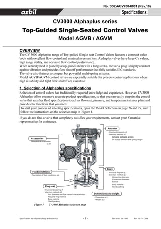
This document provides an overview and specifications for the CV3000 Alphaplus series of top-guided single-seated control valves from Yamatake Corporation. The valves feature a compact body, excellent flow control, high Cv values, and accurate flow performance. Selection details are provided for valve body specifications including size, pressure rating, end connection, materials, and leakage class. Actuator specifications include type, spring ranges, supply pressure, and finish. Tables list allowable differential pressures for each valve model and actuator combination.
![No. SS2-AGV200-0001 (Rev.10) Yamatake Corporation
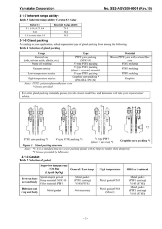
2. Basic model numbers 3-1-4 Bonnet style
We manufacture bonnets that can be used at fluid
Basic model: 1/2 to 4 inches temperatures ranging from -196°C to 400°C.
Model AGVB: JIS 10K, ANSI 150, JPI 150 Table 1 [Unit: °C]
Model AGVM: JIS 16K, JIS 20K, JIS 30K, ANSI 300, JPI 300
Body material
SCPH 2 SCS13A/SCS14A
Bonnet
3. Optional specifications
Plain -5 to +230 -17 to +230
3-1 Body Extension type I -45 to -17
+230 to +400
Figure 2 shows optional specifications of the body. (High•Low temperature) +230 to +400
Extension type II
Gland packing - -196 to -45
(Liquid O2•N2)
Bonnet
Flange standard
(flanged) For fluid temperatures outside the above temperature
Plug & Seat-ring
range, we recommend a selection from the CV3000
Body series of control valves.
3-1-5 Body, plug and seat ring materials
For combinations of body, plug and seat ring materials
and their applicable temperature ranges, see Table 7. In
Connection diameter Port diameter (normal) some ranges the plug seat ring material needs hardening
(nominal) treatment. See Figure 8. When you select a soft seat,
refer to Figure 9.
Figure 2 Body structure
For materials other than those shown in Table 7, we
3-1-1 Nominal size recommend a selection from the CV3000 series of
Yamatake manufactures diameters from 1/2 inch (15 control valves, or other Yamatake series of control
mm) to 4 inches (100 mm) as shown in Table 6. valves.
For other diameters, we recommend a selection from 3-1-6 Valve seat leakage
the CV3000 series of control valves. For the seat leak performance when the valve is fully
closed, select from among the following four
3-1-2 Port size and flow control characteristics
classifications, which conform to IEC60534-4-1999 and
The selection of the port size and the rated Cv value falls JIS B 2007-1993:
within the scope of Table 1 according to the Nominal
size. For nominal sizes 1inch (25 mm) or less, port sizes Class IV: 10-4 × rated Cv value
are expressed in terms of Cv values. Flow control (0.01% of rated Cv value)
characteristics depend on the rated Cv value, be set to Class IV-S1: 5 × 10⁻⁶ X rated Cv value
linear model or equal percentage model. (0.0005% of rated Cv value)
Based on the rated Cv value and the calculated Class V: 1.8 × 10⁻⁴ × Valve differential pressure (MPa)
necessary Cv value, check the controllability (valve × Port size (mm) l/h
position) using the flow control characteristics Tables Class VI:3 × valve differential pressure (MPa)
in Figure 4, 5, and 6. × leakage coefficient ml/min. shown below
3-1-3 Pressure rating and end connection Table 2 Leakage coefficient value
(flange type) Nominal size 1 1¼ 1½ 2 2½ 3 4
We manufacture JIS 10K RF, ANSI 150 RF, JPI 150 RF, inches (mm) (25) (32) (40) (50) (65) (80) (100)
JIS 16K RF, 20K RF, 30K RF, ANSI 300RF and JPI 300 RF. Leakage
0.15 0.17 0.23 0.36 0.51 0.62 1.20
Option: Socket weld, butt weld coefficient
For other rated pressures and connection types, you For shutoff valves, choose either Class V or VI.
are recommended to consider the CV 3000 series of To maintain over time the performance of Class V or
control valves. Class IV-S1 valves, the plug seat material requires
hardening treatment. Class IV valves, seat type is soft
seat (PTFE). Additionally with the selection of the
low-temperature service, oil-proof, water-proof
service for the choice of material seat, the set leakage
is Class IV-S1.
-2-](https://image.slidesharecdn.com/agvbagvm-controlvalve-121130014433-phpapp02/85/Agvbagvm-control-valve-2-320.jpg)
![Yamatake Corporation No. SS2-AGV200-0001 (Rev.10)
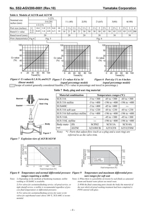
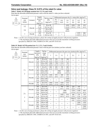
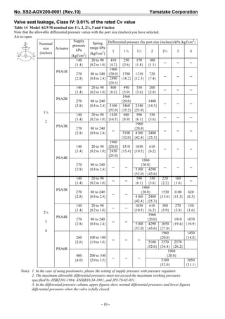
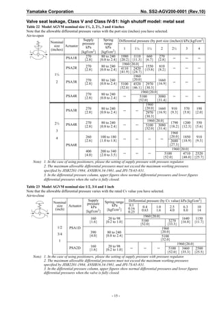
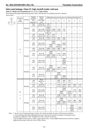
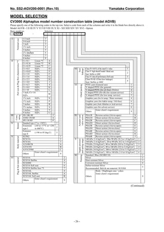
Valve seat leakage, Class V and Class IV-S1: high shutoff model: metal seat
Table 17 Model AGVB nominal size 1/2, 3/4 and 1 inch
Note that the allowable differential pressure varies with the rated Cv value you have selected.
Air-to-open
Supply 2
Nominal Spring range Differential pressure (by Cv value) kPa{kgf/cm }
pressure 0.1
size Actuator kPa 0.4 1.0 2.5 6.3 10
kPa 2 0.16
(inch) {kgf/cm } 0.63 1.6 4.0 8.0 14
{kgf/cm2} 0.25
1/2
80 to 240 1960
3/4 PSA1R 270{2.8}
{0.8 to 2.4} {20.0}
1
Note) 1. In the case of using positioners, please the setting of supply pressure with pressure regulator.
2. The maximum allowable differential pressures must not exceed the maximum working pressures
specified by JISB2201-1984, ANSIB16.34-1981, and JPI-7S-65-831.
Table 18 Model AGVB nominal size 1½, 2, 2½, 3 and 4 inches
Note that the allowable differential pressure varies with the port size (inches) you have selected
Air-to-open
Supply 2
Nominal Spring range Differential pressure (by port size (inches)) kPa{kgf/cm }
pressure
size Actuator kPa
kPa 1 1¼ 1½ 2 2½ 3 4
(inches) {kgf/cm2}
{kgf/cm2}
270 80 to 240 1960 1110 660 270
PSA1R -- -- --
{2.8} {0.8 to 2.4} {20.0} {11.3] {6.7} {2.8}
270 80 to 240 1960 1550 810
1½ PSA2R -- -- -- --
{2.8} {0.8 to 2.4} {20.0} {15.8} {8.2}
270 80 to 240 1960 1660
2 PSA3R -- -- -- -- --
{2.8} {0.8 to 2.4} {20.0} {16.9}
270 80 to 240 1960
PSA4R -- -- -- -- -- --
{2.8} {0.8 to 2.4} {20.0}
270 80 to 240 1960 1660 910 570 190
PSA3R -- --
{2.8} {0.8 to 2.4} {20.0} {16.9} {9.3} {5.8} {2.0}
2½
270 80 to 240 1960 1790 1200 550
PSA4R -- -- --
{2.8} {0.8 to 2.4} {20.0} {18.2} {12.3} {5.6}
3
260 100 to 180 1960 1850 910
-- -- -- --
{2.6} {1.0 to 1.8} {20.0} {18.9} {9.3}
4 PSA6R
400 200 to 340 1960
-- -- -- -- --
{4.0} {2.0 to 3.5} {20.0}
Note) 1. In the case of using positioners, please the setting of supply pressure with pressure regulator.
2. The maximum allowable differential pressures must not exceed the maximum working pressures
specified by JISB2201-1984, ANSIB16.34-1981, and JPI-7S-65-831.
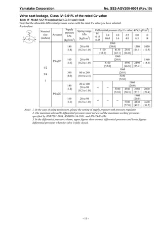
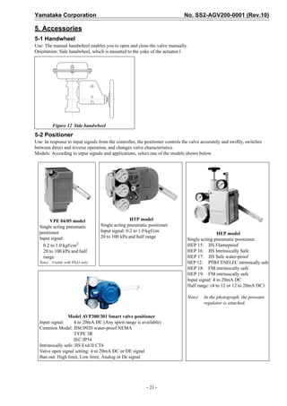
Table 19 Model AGVB nominal size 1/2, 3/4 and 1 inch
Note that the allowable differential pressure varies with the rated Cv value you have selected.
Air-to-close
Supply Differential pressure (by Cv value) kPa{kgf/cm2}
Nominal Spring range
pressure 0.1
size Actuator kPa 0.4 1.0 2.5 6.3 10
kPa 2 0.16
(inch) 2} {kgf/cm } 0.63 1.6 4.0 8.0 14
{kgf/cm 0.25
160 20 to 98 1640 1150
1/2
{1.6} {0.2 to 1.0} 1960 {16.8} {11.7}
PSA1D
390 80 to 240 {20.0}
3/4
{4.0} {0.8 to 2.4}
160 20 to 98
1 PSA2D -- -- -- --
{1.6} {0.2 to 1.0}
Note) 1. In the case of using positioners, please the setting of supply pressure with pressure regulator.
2. The maximum allowable differential pressures must not exceed the maximum working pressures
specified by JISB2201-1984, ANSIB16.34-1981, and JPI-7S-65-831.
- 13 -](https://image.slidesharecdn.com/agvbagvm-controlvalve-121130014433-phpapp02/85/Agvbagvm-control-valve-13-320.jpg)
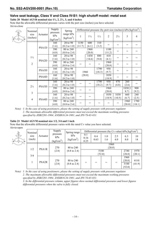

![Yamatake Corporation No. SS2-AGV200-0001 (Rev.10)
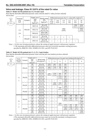
(Continued from previous page)
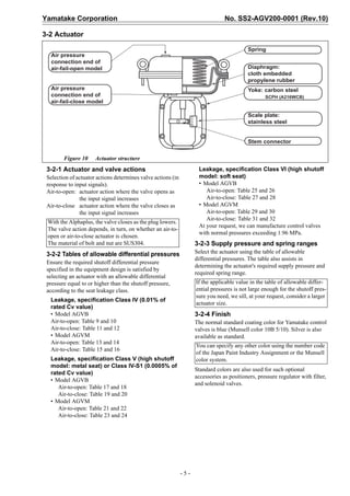
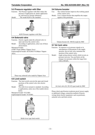
Optional selection Option
-
XII Manual No selection X No selection X
handwheel Side handwheel S Vinyl-sheathed copper tube + cap A
XIII Positioner No selection X Exposed bolts & nuts: SUS304 *2 B
Smart I/P [AVP300] C
Smart I/P (with motion transmitter) [AVP301] D
Copper-free treatment (wetted part) E
Smart I/P JIS Flameproof type [AVP300] G Others 9
Smart I/P JIS Flameproof type
[AVP301] H
(with motion transmitter) * For [Others] in the additional specification
Smart I/P remote type [AVP200] J check the following items
Smart I/P remote type
[AVP201] K [ ] Material certificates of body & bonnet.
(With motion transmitter)
Smart I/P JIS Flameproof type [ ] Strength calculation
[AVP200] L
Remote type [ ] Air piping connection 1/4 inch NPT
Smart I/P JIS Flameproof type, Remote type [ ] Flow characteristics inspection
[AVP201] M
(with motion transmitter) [ ] Radiographic test (RT)
I/P JIS water-proof [HEP17] 1 [ ] Liquid penetrant test (PT)
I/P new JIS flameproof [HEP15] 2
Compact pneumatic type (PSA1 only) [VPE] 5 Applicable fluid
Pneumatic type only [HTP] 6
High-pressure gas regulation approval
Gas type [ ] Toxic gas
Enter client’s request [ ] Flammable gas
Others 9
[ ] Special HP. gas
XIV Combination No selection X
filter and Yes (without pressure gauge) [KZ03] (for AVP, HEP, HTP) 1 [ ] Others
regulator Yes (with pressure gauge) [KZ03] (for VPE) 2 Grade
Enter client’s request [ ] Grade 1 [ ] Grade 2 [ ] Grade 3
Others 9
Design temperature
XV Solenoid No selection X deg.C
valves Design pressure
General purpose J320G174 (ASCO) 1
MPa kPa
JIS flameproof type JE3J320G174 (ASCO) 3 Applicable plant name
Enter client’s request
Others 9
XVI Limit switch No selection X Note)
Water-proof single mount [VCL5001] 1 *1 Applicable to stud bolts for body, bolts and
Water-proof dual mount [VCL5001] 2 nuts for handwheel, accessories, and
JIS flameproof single mount [VCX5001] 3 actuators
JIS flameproof dual mount [VCX5001] 4 *2 Positioner action
Enter client’s request Direct action: Increase pneumatic output
Others 9 when input signal increased.
Reverse action: Decreased pneumatic output
when input signal increased.
Positioner Input signal:
mA, kPa, kgf/cm² *3 Output characteristics conversion
Change of action: [ ] No (direct), [ ] Yes (reverse) *2 In case of “None”, A to C shall be linear
characteristics, and D to U shall be EQ%
Change of output characteristics: [ ] No, [ ] Yes *3 characteristics.
Position transmitting feature: (for model AVP301 only): In case of “Yes”, A to C shall be EQ%
[ ] 4-20mA, [ ] DE *4 characteristics, and D to U shall be linear
Compression packings HEP [ ] None, [ ] 1 piece characteristics.
JIS flameproof AVP [ ] No, [ ] Yes Those above conversion shall be made by
POSITIONER.
Solenoid valves Energize: [ ]CV CONTROL, [ ]CV CLOSE, [ ]CV OPEN, [ ]OTHERS *4 AVP position transmitting feature (model
De-energize: [ ]CV CONTROL, [ ]CV CLOSE, [ ]CV OPEN, [ ]OTHERS AVP301 only)
Power supply [ ]AC, [ ]DC V Hz Four-wire connection is required when use
position transmitting feature.
Limit switch Operating position: [ ]CLOSE, [ ]OPEN, [ ]OPEN&CLOSE, [ ]OTHERS DE: Digital signal common to YC group.
*5 Plug and seat materials shall be SUS316
[ ] Pressure-tight packing adaptor stellite face or SUS316L stellite seat when Cv
values are 0.1 to 0.16 and 0.25.
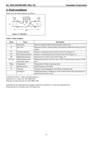
Please fill in the blanks with the necessary information.
Fluid name Slurry Note
MAX NOR MIN Unit
Flow rate
Upstream pressure MPa. kPa
Downstream pressure MPa. kPa
Process data
Differential pressure MPa. kPa
Differential pressure
MPa. kPa
when fully closed
Temperature °C, °F
Specific gravity
Viscosity cP, cSt
Flashing % %
Calculated CV value
- 27 -](https://image.slidesharecdn.com/agvbagvm-controlvalve-121130014433-phpapp02/85/Agvbagvm-control-valve-27-320.jpg)
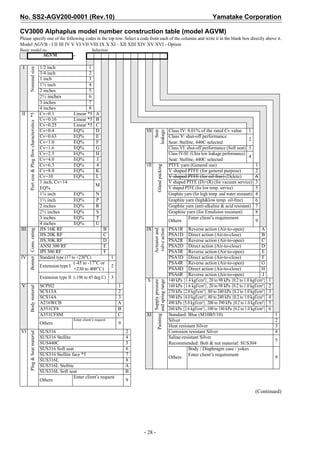
![Yamatake Corporation No. SS2-AGV200-0001 (Rev.10)
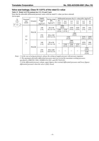
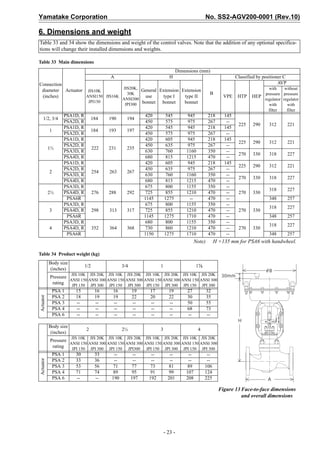
(Continued from previous page)
Optional selection Option
-
XII Manual hand- No selection X No selection X
wheel Side mount S Vinyl-sheathed copper tube + cap A
XIII Positioner No selection X Exposed bolts & nuts: SUS304 *1 B
Smart I/P [AVP300] C Copper-free treatment (to process
Smart I/P (with position Tx) [AVP301] D
E
media)
Smart I/P JIS Flameproof type [AVP300] G Others 9
Smart I/P JIS Flameproof type
[AVP301] H * For [Others] in the additional specification
(with motion transmitter)
Smart I/P remote type [AVP200] J check the following items
Smart I/P remote type
[AVP201] K
(With motion transmitter) [ ] Material certificates of body & bonnet.
Smart I/P JIS Flameproof type [ ] Strength calculation
[AVP200] L
Remote type [ ] Air piping connection 1/4 inch NPT
Smart I/P JIS Flameproof type, Remote [ ] Flow characteristics inspection
[AVP201] M
type (with motion transmitter) [ ] Radiographic test (RT)
I/P JIS water-proof [HEP17] 1 [ ] Liquid penetrant test (PT)
I/P new JIS flameproof [HEP15] 2
Compact pneumatic type (PSA1 Applicable fluid
High-pressure gas regulation approval
[VPE] 5 Gas type [ ] Toxic gas
only)
Pneumatic Std type [HTP] 6 [ ] Flammable gas
Enter client’s requirement [ ] Special HP. gas
Others 9
[ ] Others
XIV Combination No selection X Grade
filter and regu- Yes (without pressure gauge) [KZ03] [ ] Grade 1 [ ] Grade 2 [ ] Grade 3
1
lator (for AVP, HEP, HTP) Design temperature
Yes (with pressure gauge) [KZ03] (for VPE) 2 deg.C
Enter client’s request Design pressure
Others 9
MPa
XV Solenoid No selection X Applicable plant name
valves General purpose J320G174 (ASCO) 1
JIS flameproof type JE3J320G174 (ASCO) 3
Enter client’s requirement Note)
Others 9 *1 Applicable to stud bolts for body, bolts and
XVI Limit switch No selection X nuts for handwheel, accessories, and
Water-proof single mount [VCL5001] 1 actuators
Water-proof dual mount [VCL5001] 2 *2 Positioner action
JIS flameproof single mount [VCX5001] 3 Direct action: Increase pneumatic output
JIS flameproof dual mount [VCX5001] 4 when input signal increased.
Enter client’s requirement Reverse action: Decreased pneumatic output
Others 9 when input signal increased.
*3 Output characteristics conversion
In case of “None”, A to C shall be linear
Positioner Input signal:
characteristics, and D to U shall be EQ%
mA, kPa, kgf/cm² characteristics.
Change of action: [ ] No (direct), [ ] Yes (reverse) *2 In case of “Yes”, A to C shall be EQ%
Change of output characteristics: [ ] No, [ ] Yes *3 characteristics, and D to U shall be linear
Position transmitting feature: (for model AVP301 only): characteristics.
[ ] 4-20mA, [ ] DE *4 Those above conversion shall be made by
Compression packings HEP [ ] None, [ ] 1 piece POSITIONER.
JIS flameproof AVP [ ] No, [ ] Yes *4 AVP position transmitting feature (model
AVP301 only)
Solenoid valves Energize: [ ]CV CONTROL, [ ]CV CLOSE, [ ]CV OPEN, [ ]OTHERS Four-wire connection is required when use
De-energize: [ ]CV CONTROL, [ ]CV CLOSE, [ ]CV OPEN, [ ]OTHERS position transmitting feature.
DE: Digital signal common to YC group.
Power supply [ ]AC, [ ]DC V Hz
*5 Plug and seat materials shall be SUS316
Limit switch Operating position: [ ]CLOSE, [ ]OPEN, [ ]OPEN&CLOSE, [ ]OTHERS stellite face or SUS316L stellite seat when Cv
[ ] Pressure-tight packing adaptor values are 0.1 to 0.16 and 0.25.
Please fill in the blanks with the necessary information.
Fluid name Slurry Note
MAX NOR MIN Unit
Flow rate
Upstream pressure MPa. kPa
Downstream pressure MPa. kPa
Process data
Differential pressure MPa. kPa
Differential pressure
MPa. kPa
when fully closed
Temperature °C, °F
Specific gravity
Viscosity cP, cSt
Flashing % %
Calculated CV value
- 29 -](https://image.slidesharecdn.com/agvbagvm-controlvalve-121130014433-phpapp02/85/Agvbagvm-control-valve-29-320.jpg)