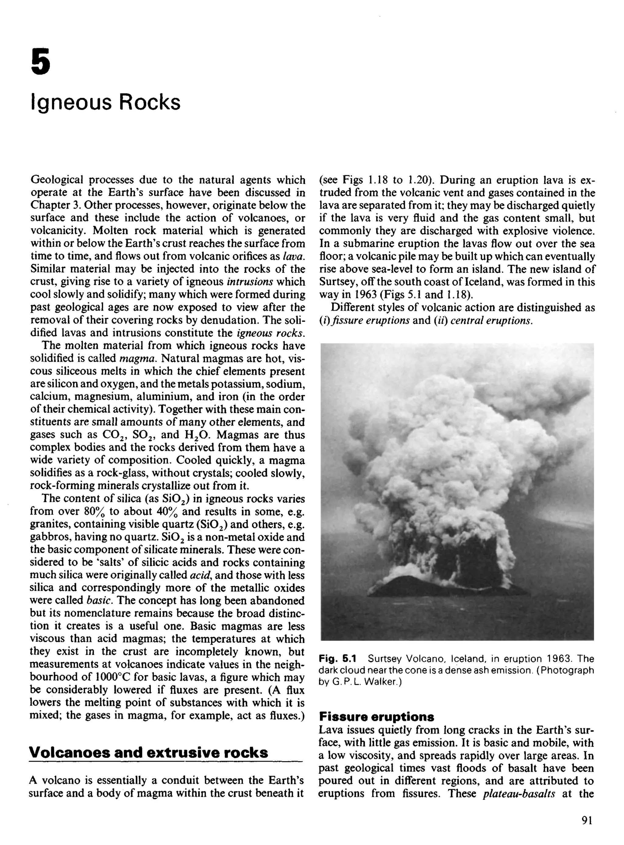
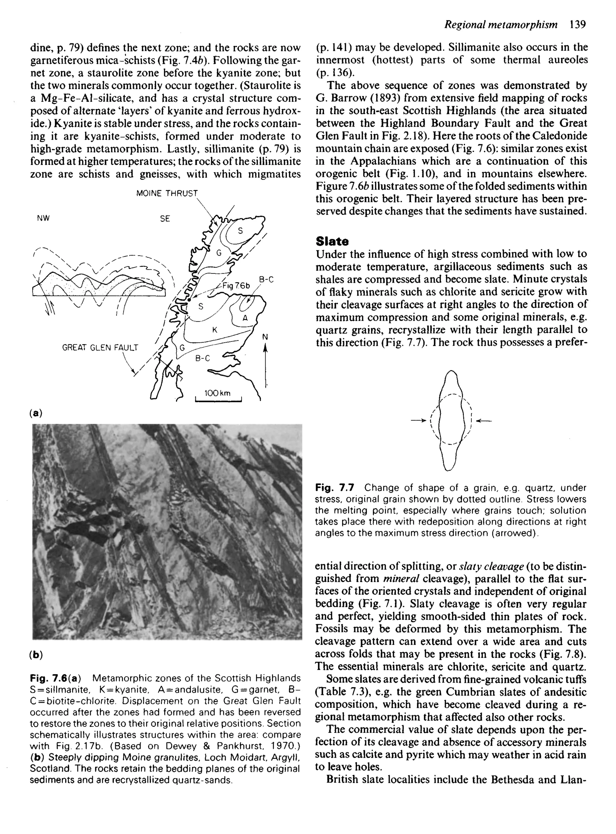
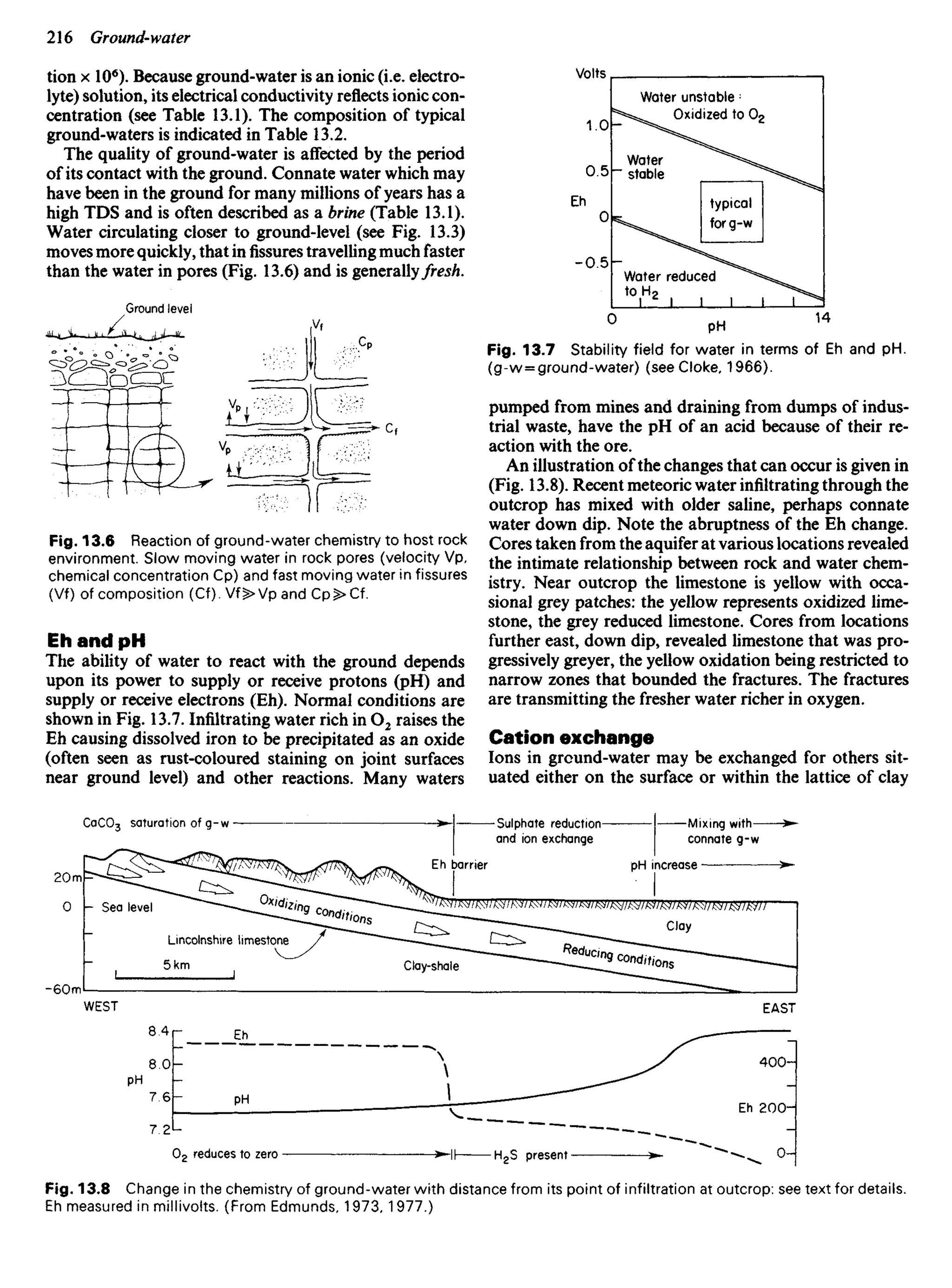
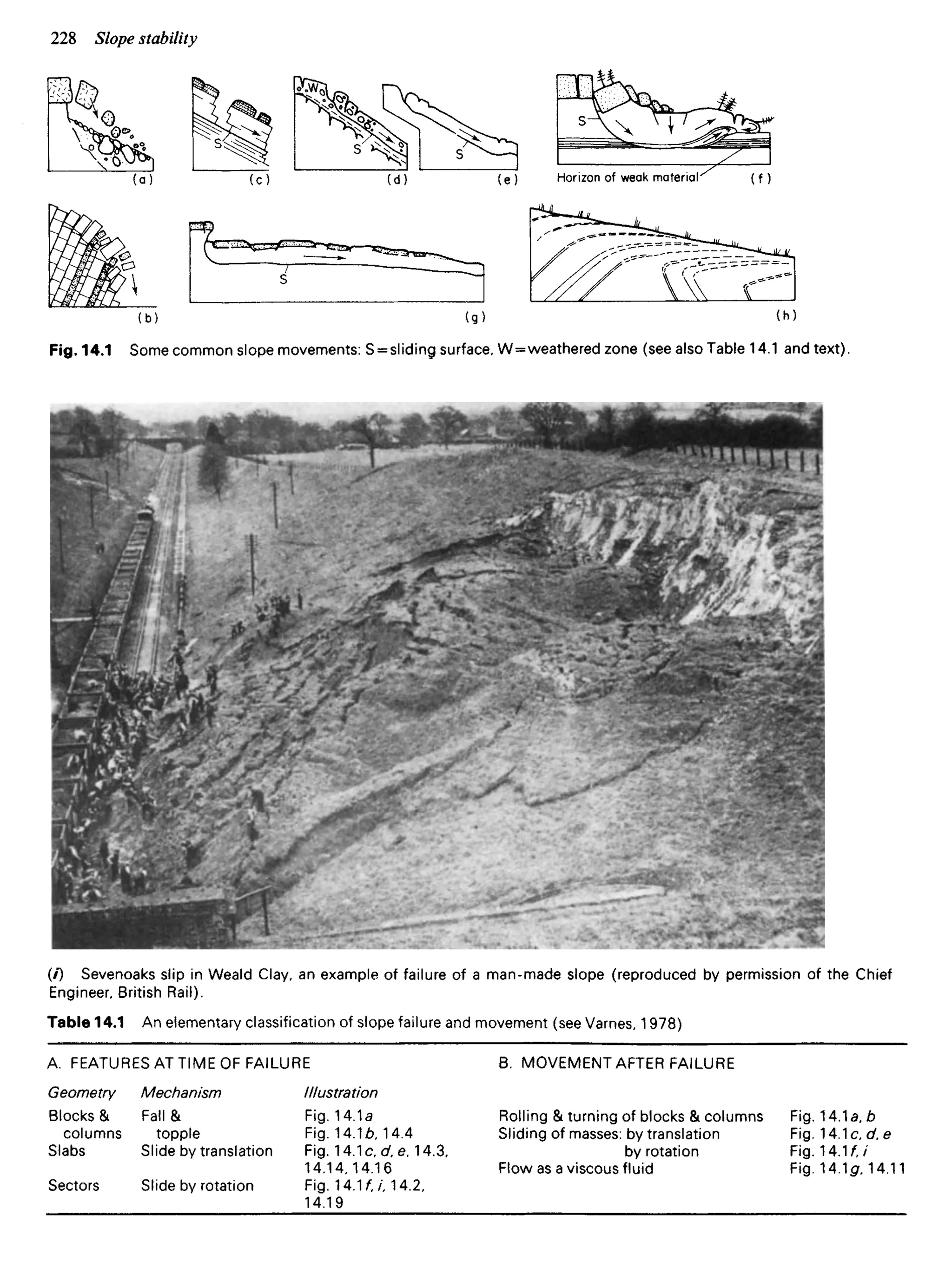
This document is the preface to the 7th edition of the textbook "A Geology for Engineers" by authors F.G.H. Blyth and M.H. de Freitas. It discusses the structure and features of the new edition, which has been completely revised and expanded with three new chapters. The preface is intended to help teachers utilizing the textbook in their geology courses for engineering students, as well as to aid students in their study of geology. Key features for teachers include chapter structure, illustrations, and support for practical work. Key features for students include text format, comprehensive headings, and references to assist further learning.


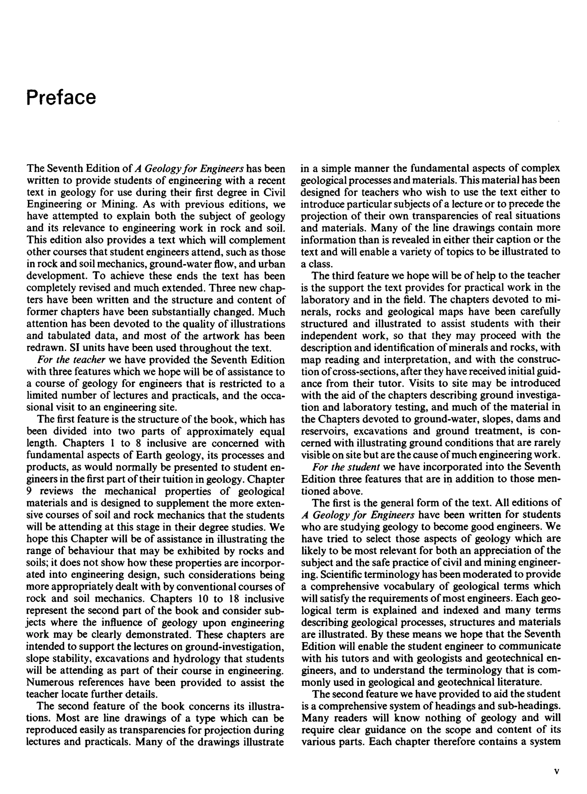

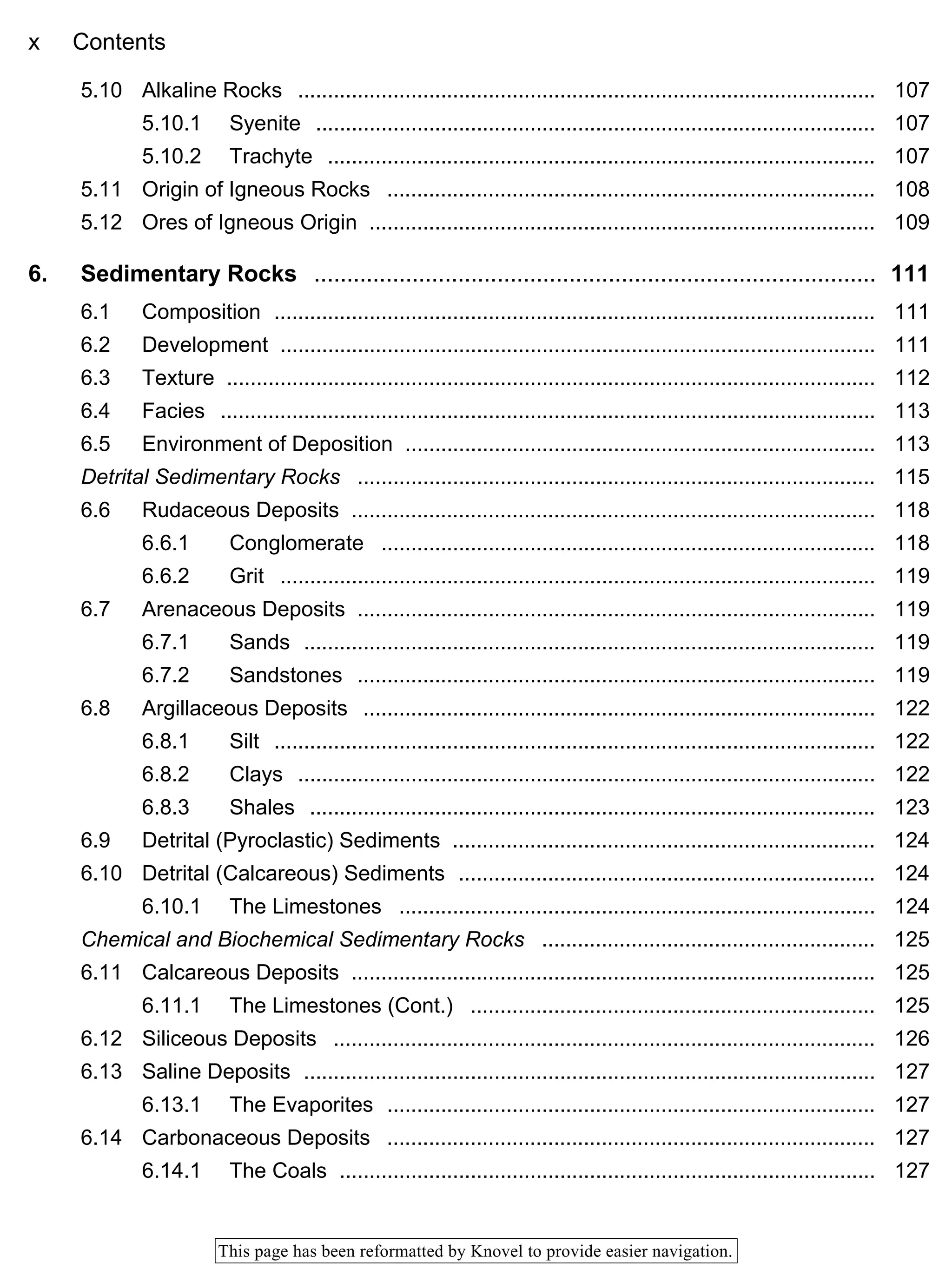
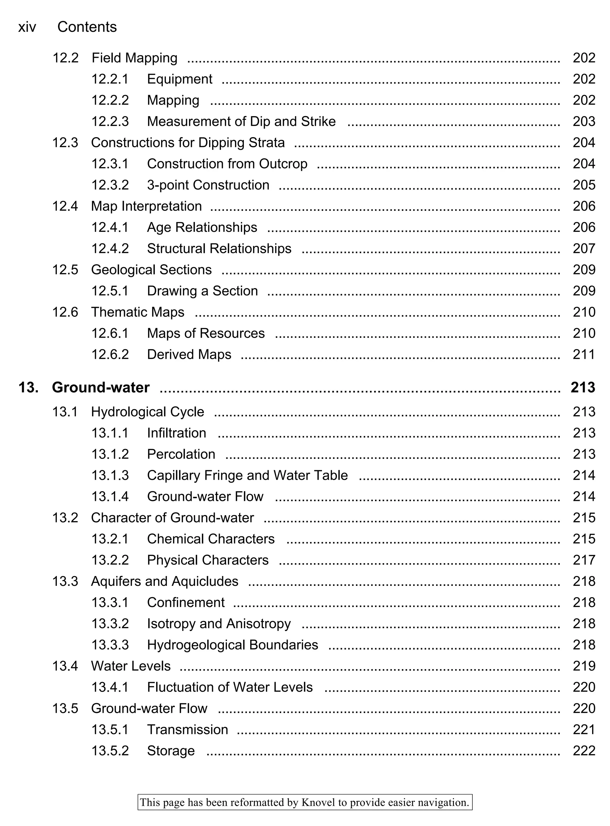

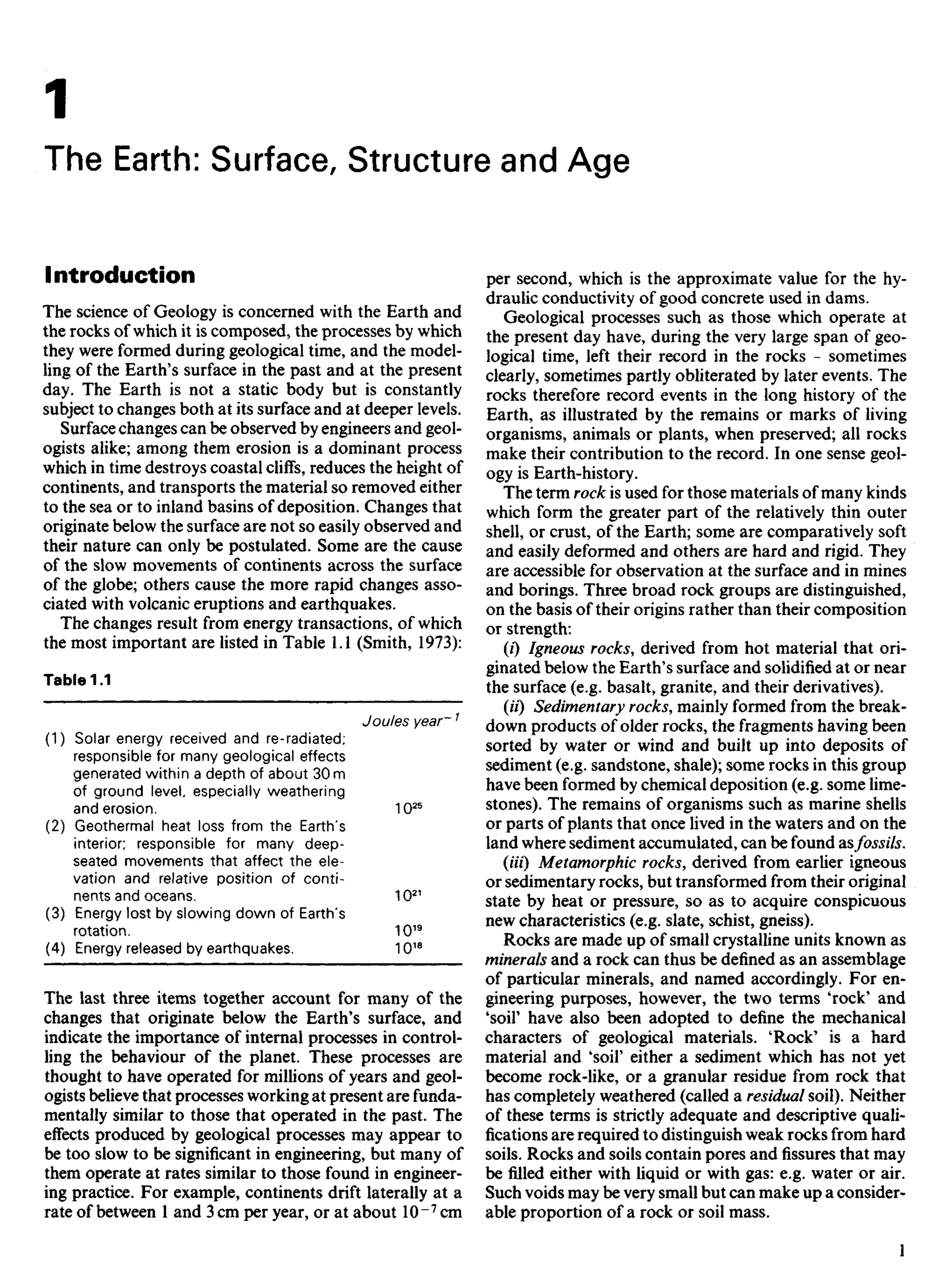
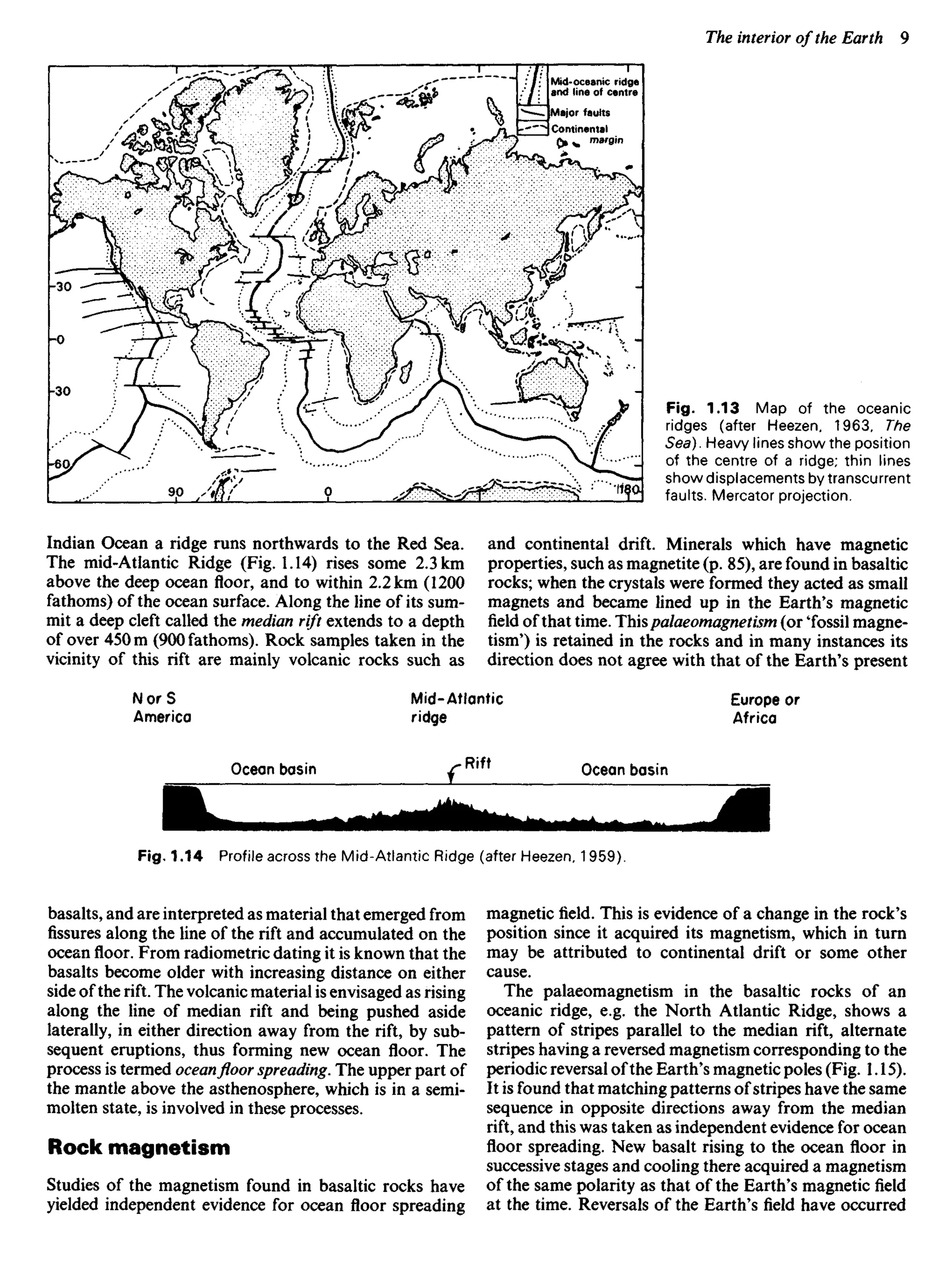

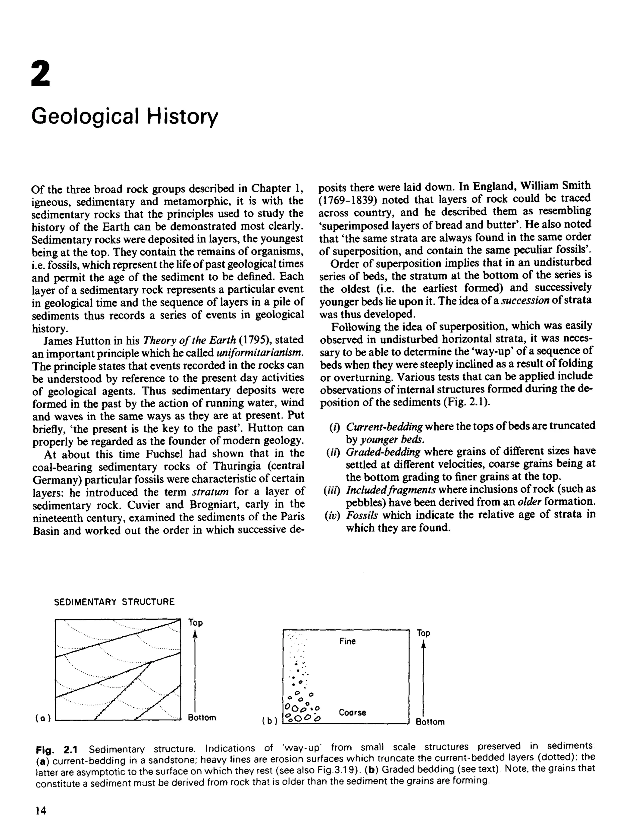

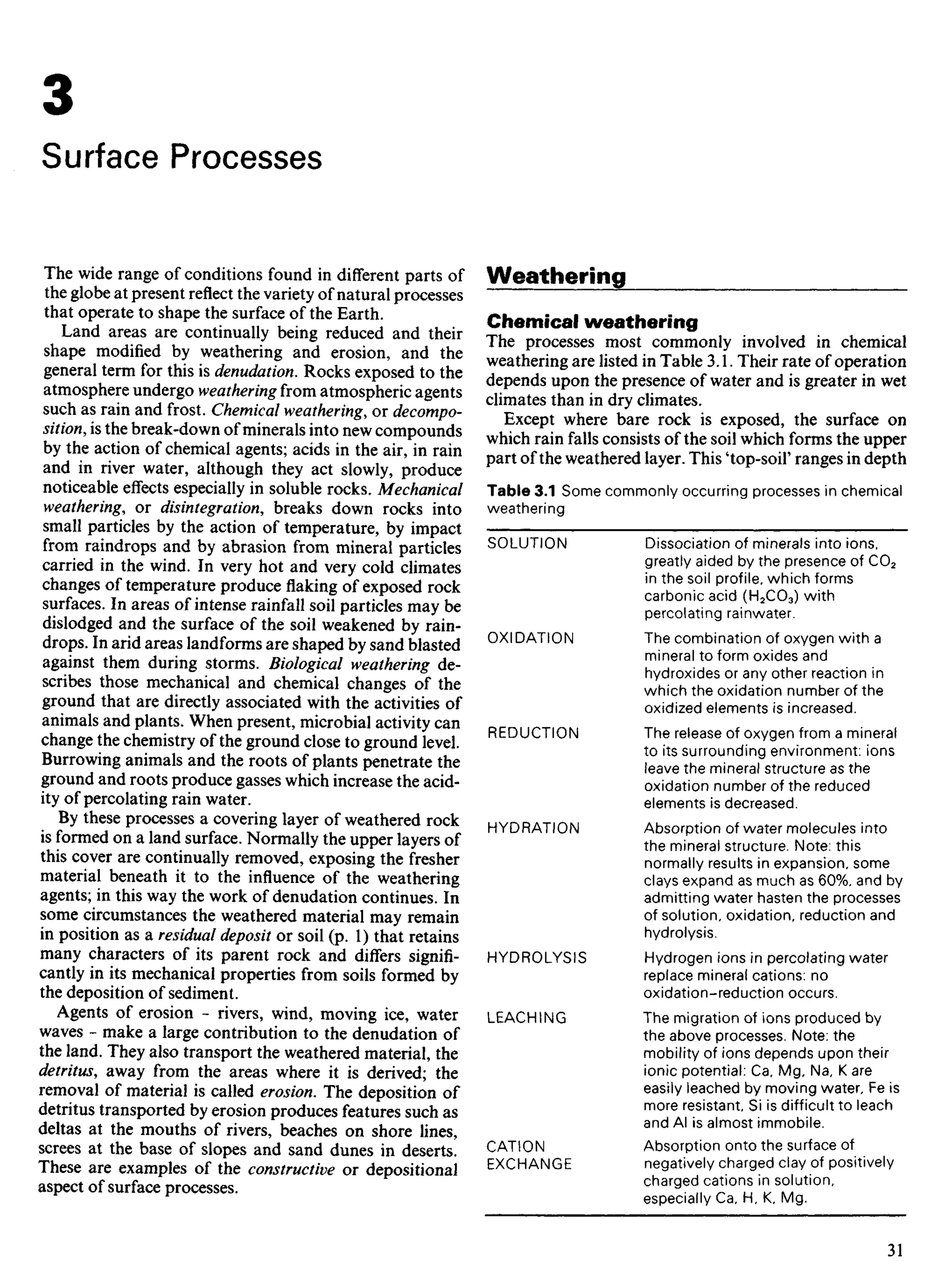
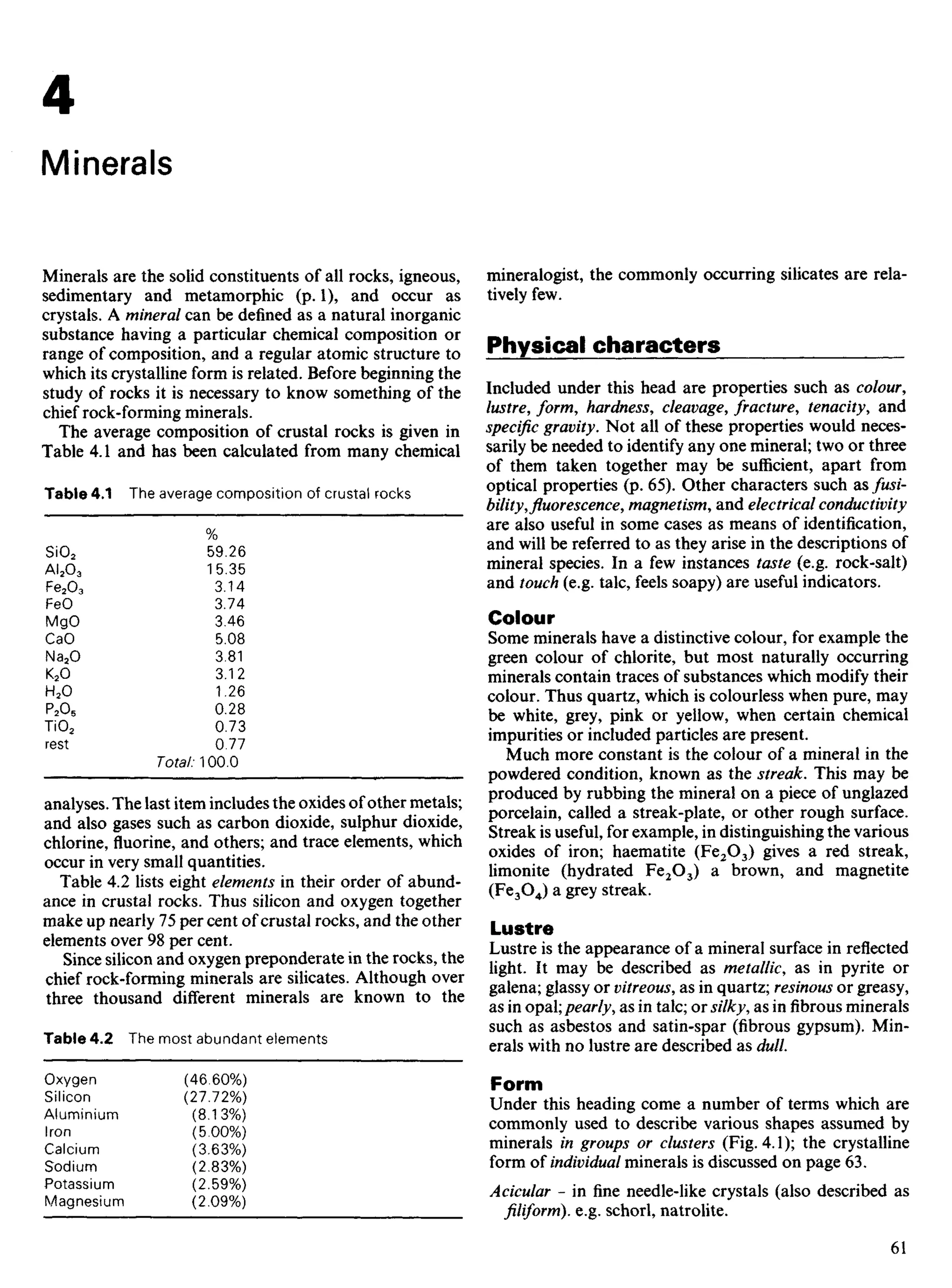
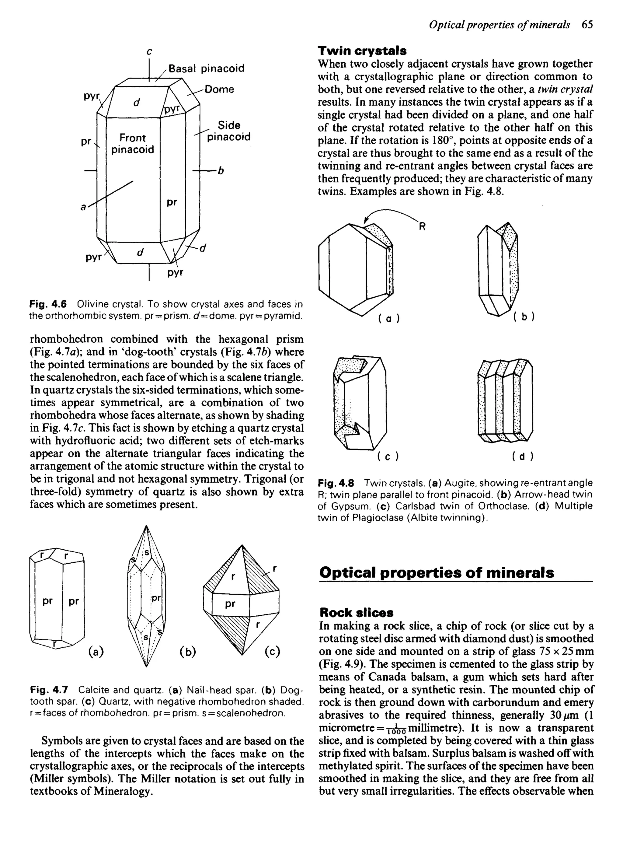
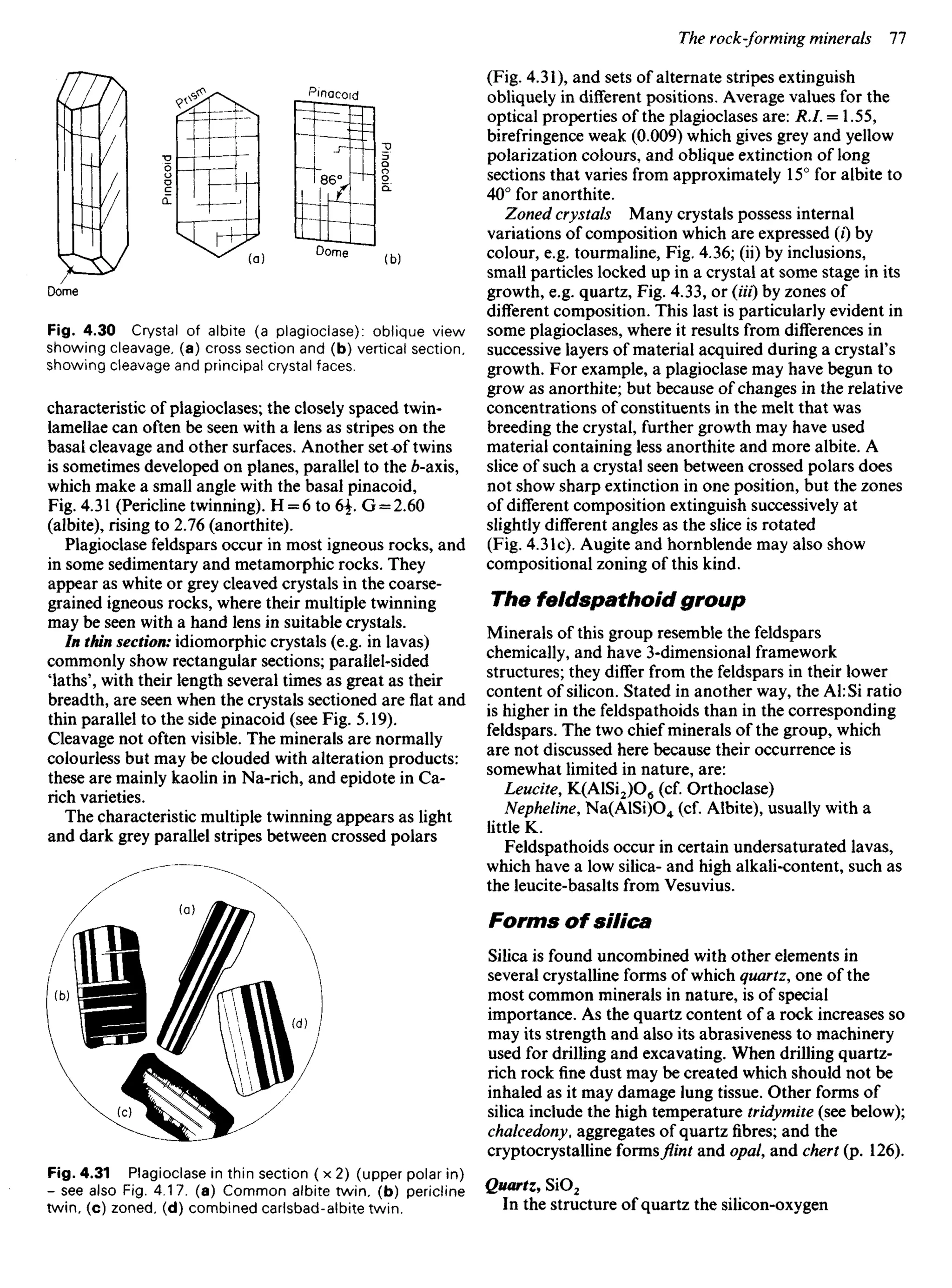


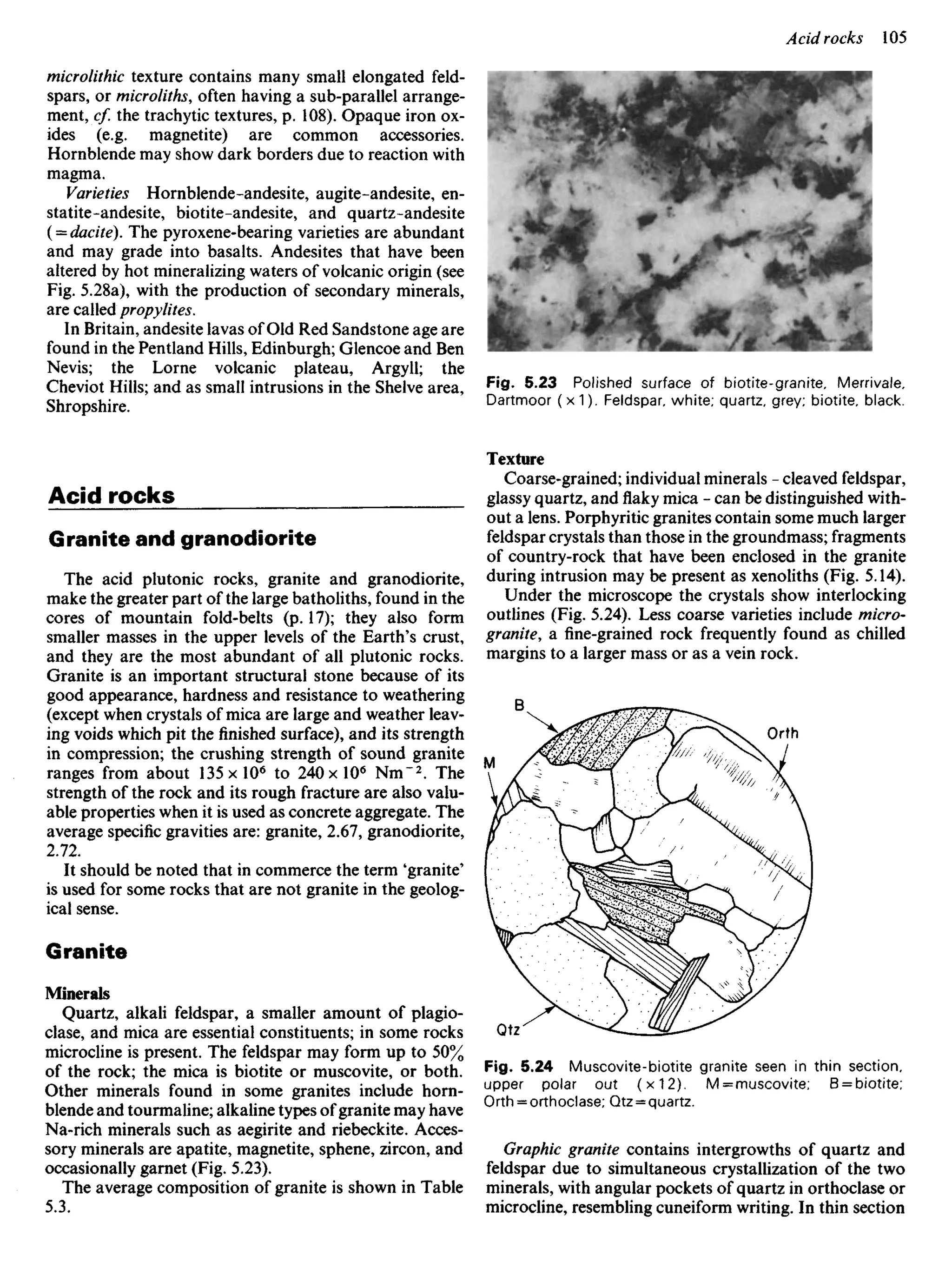
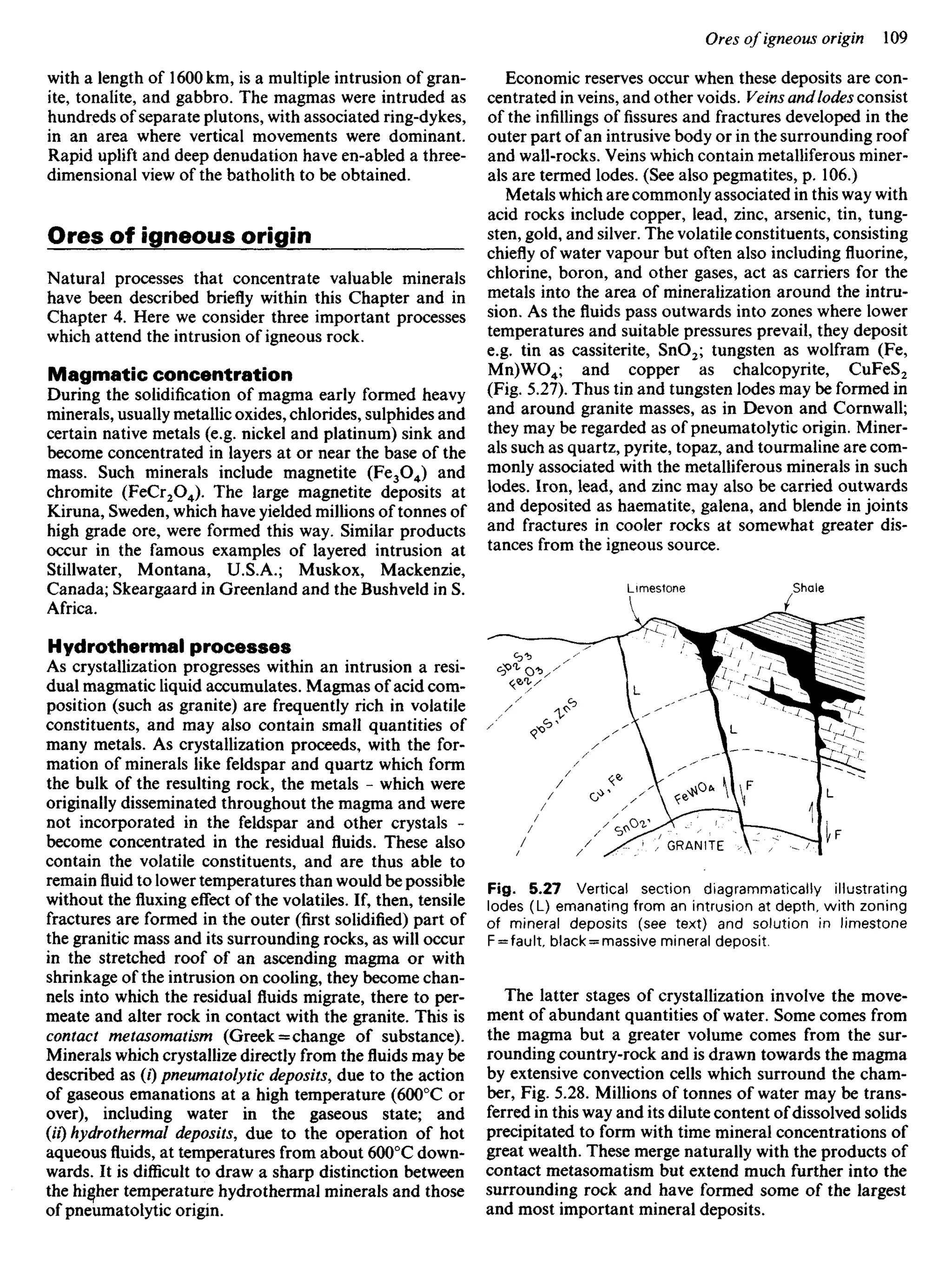
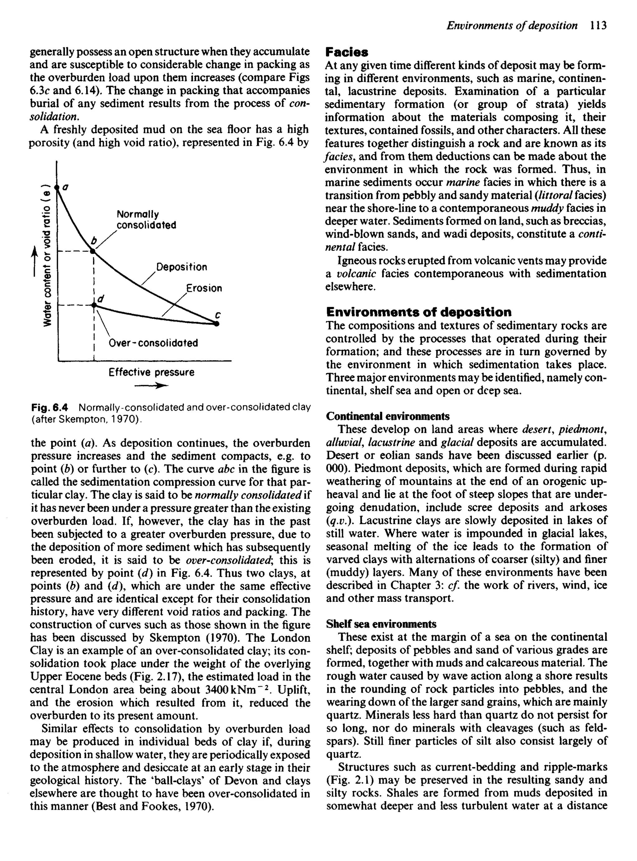
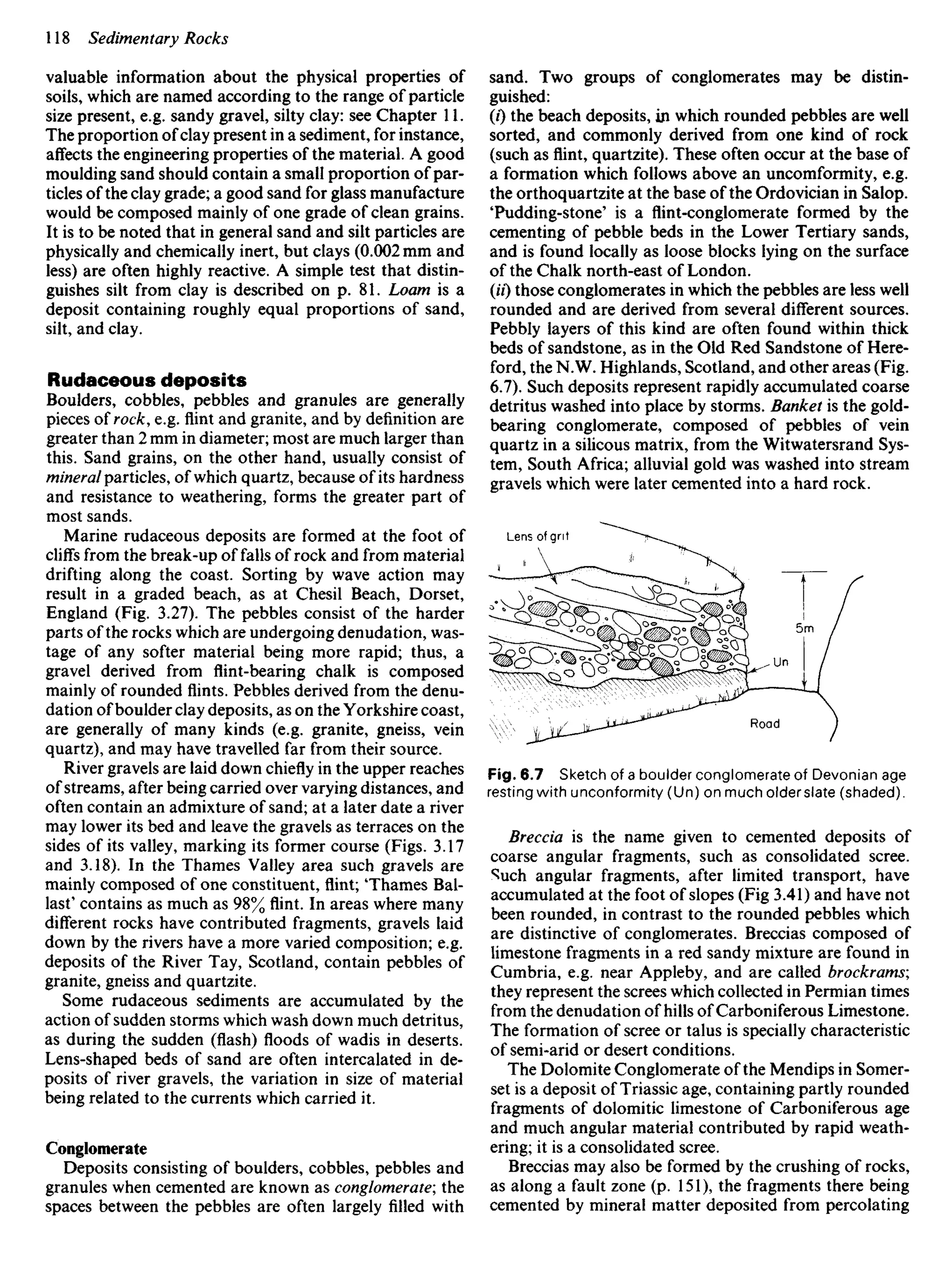
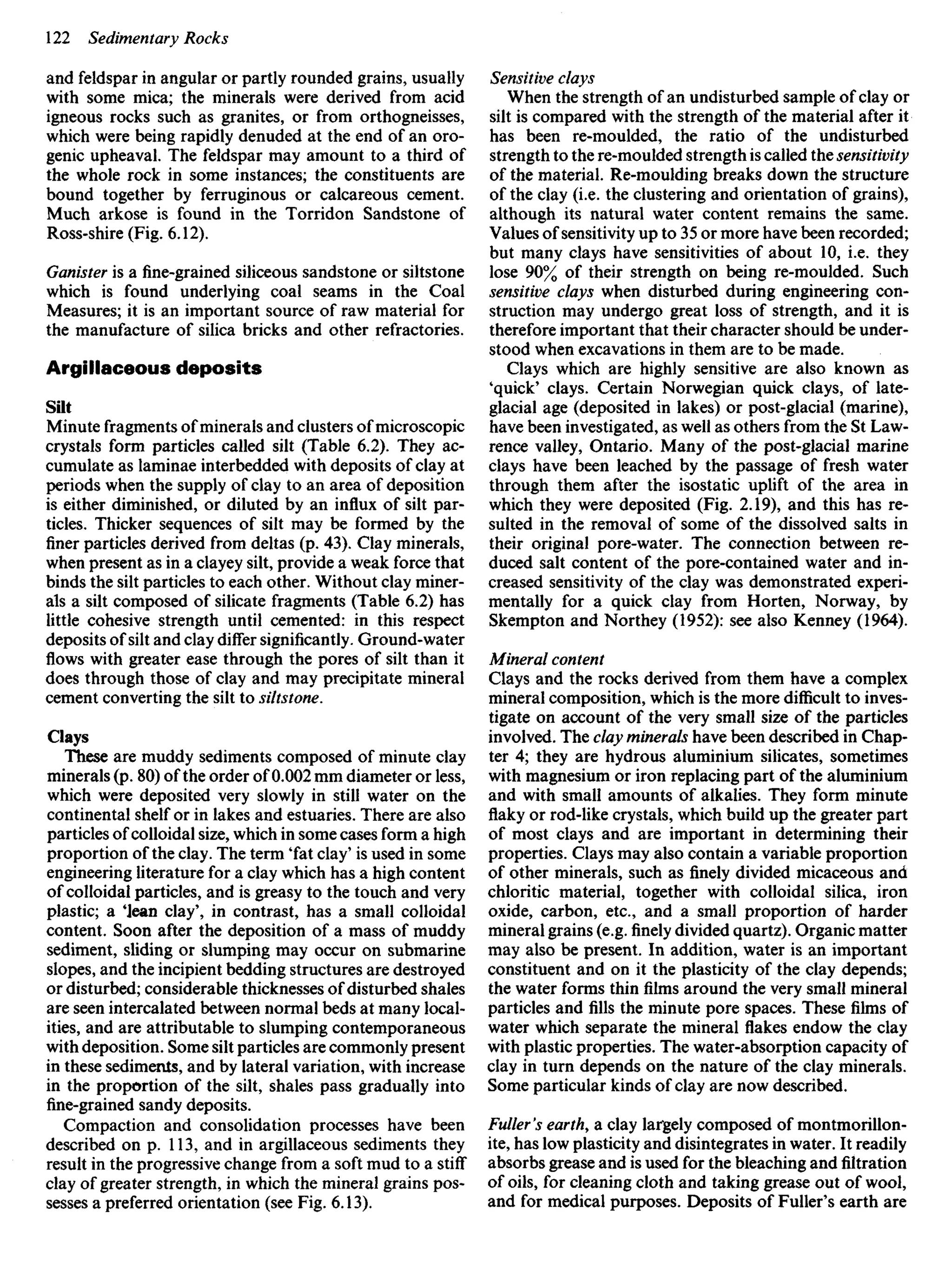
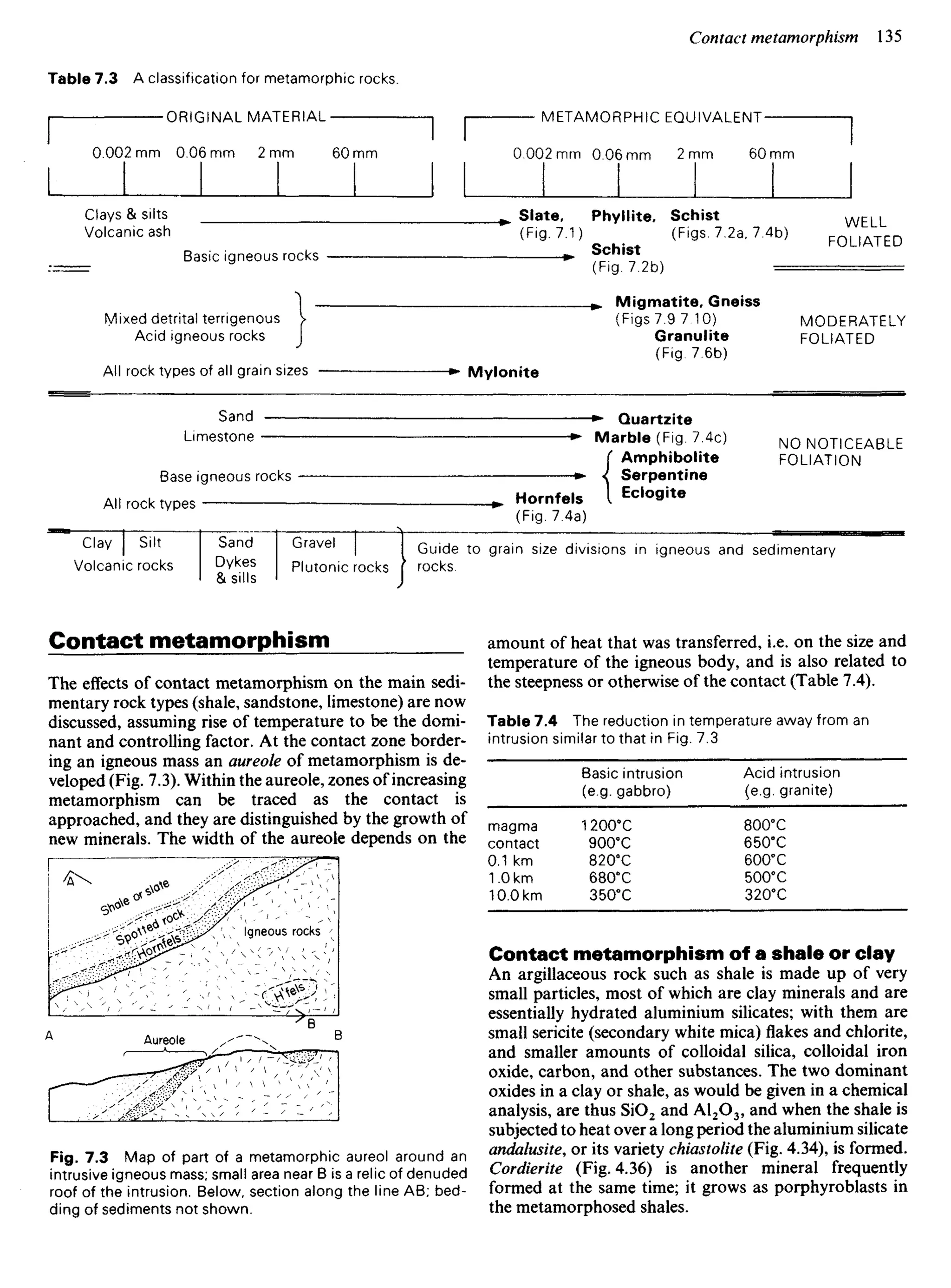
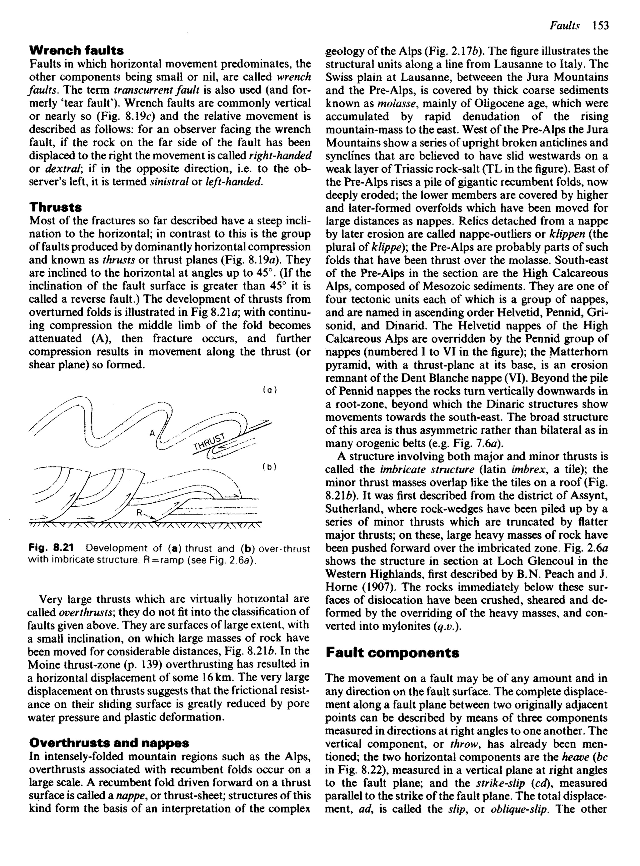
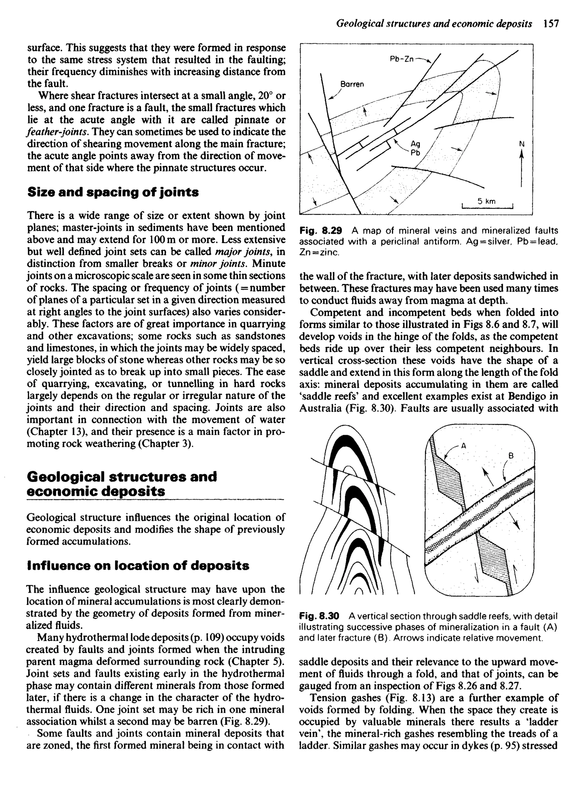
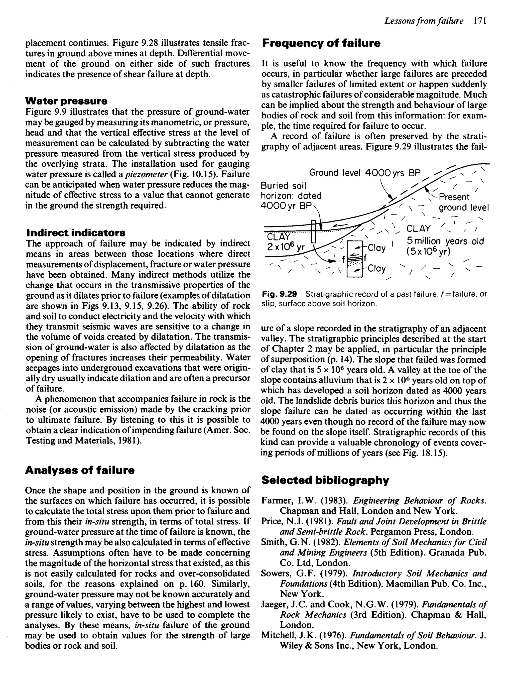
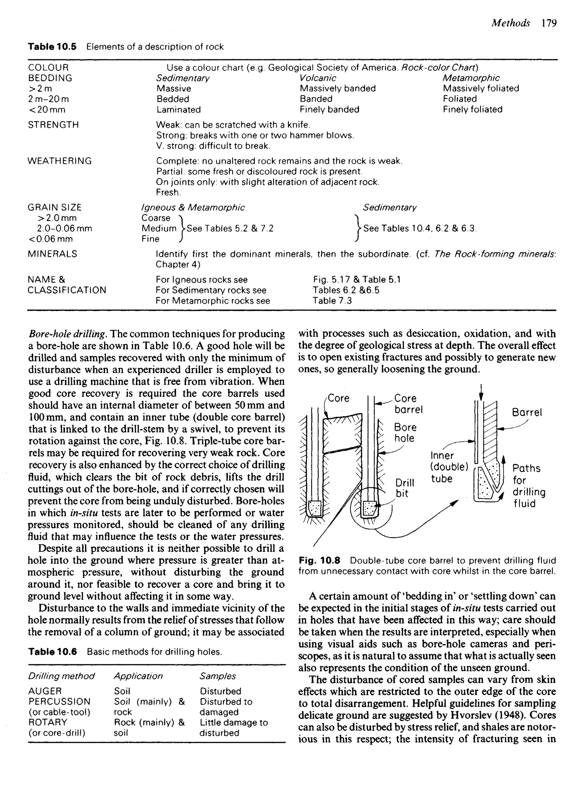
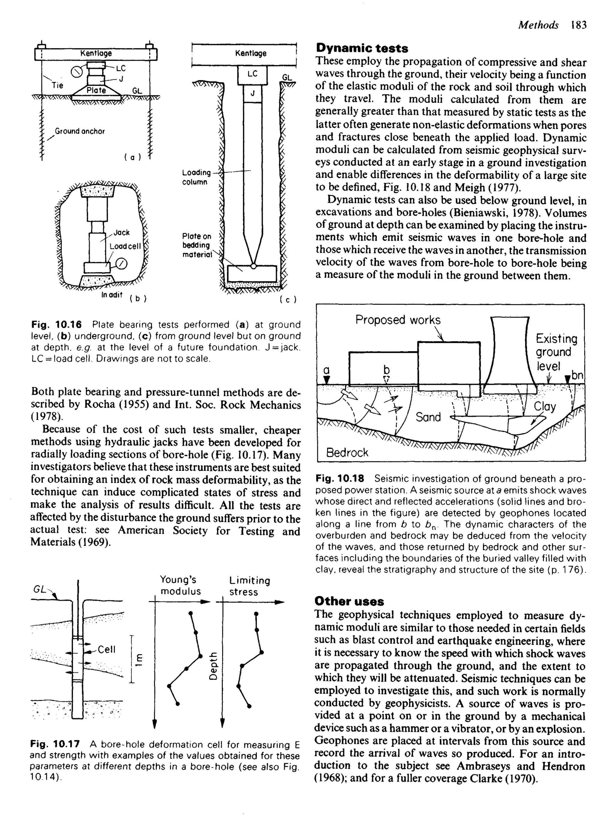
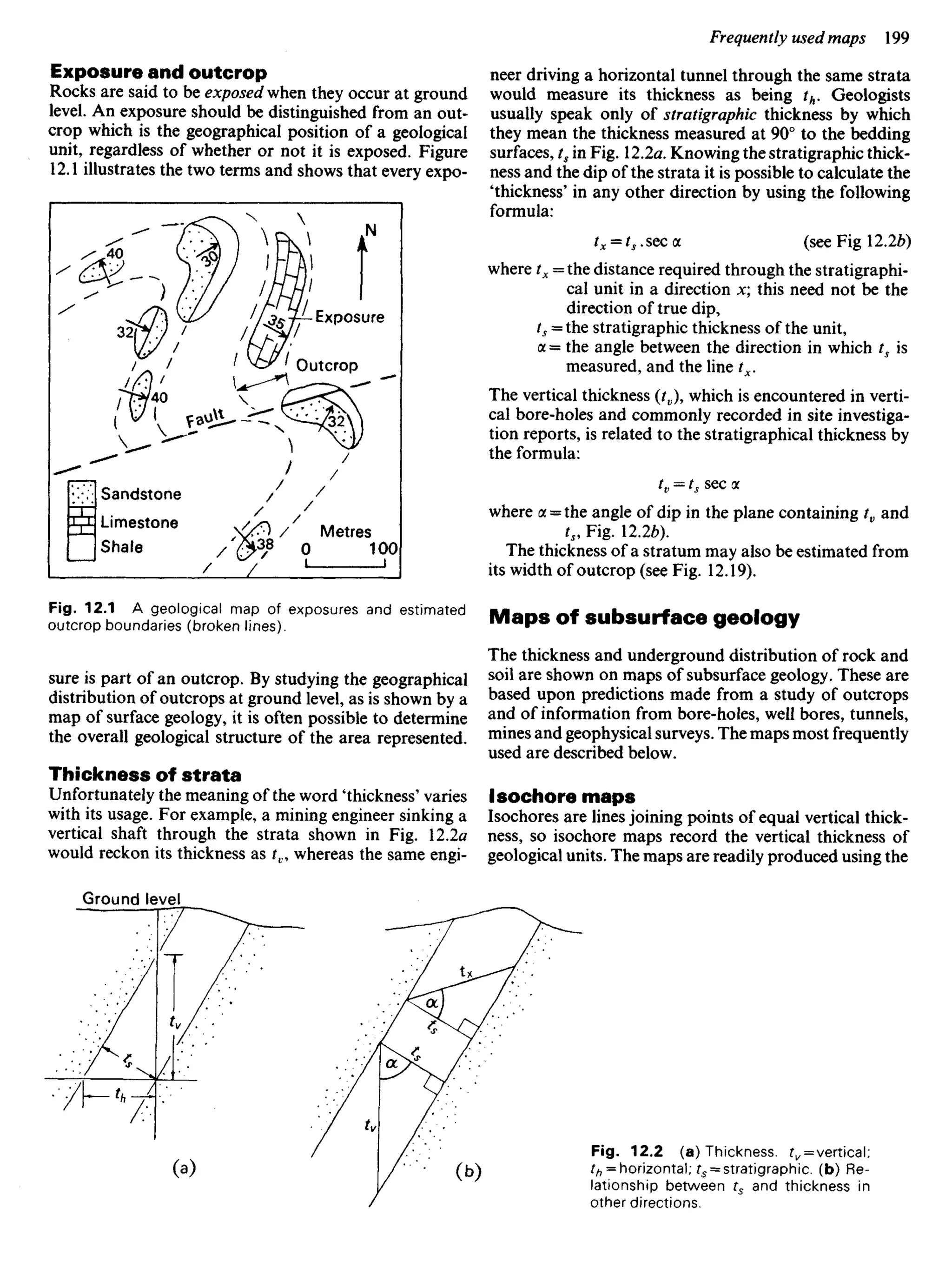
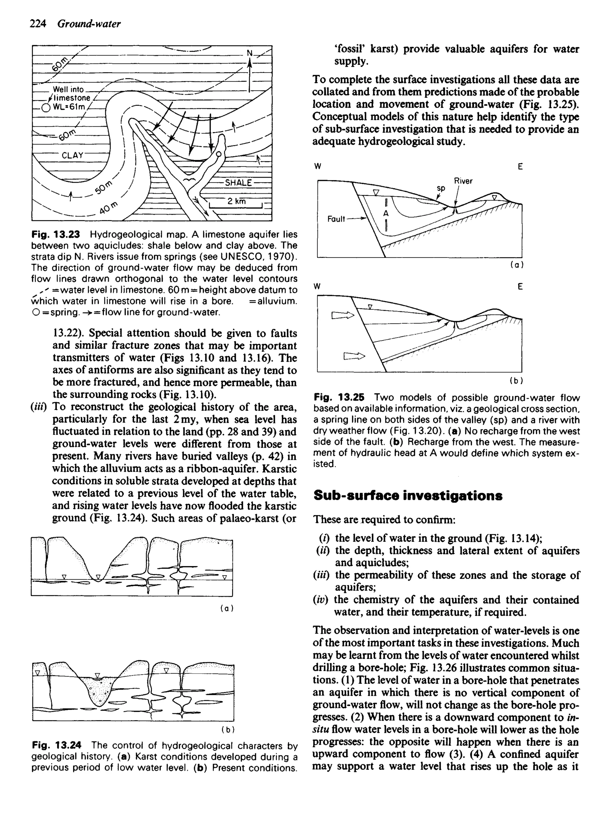
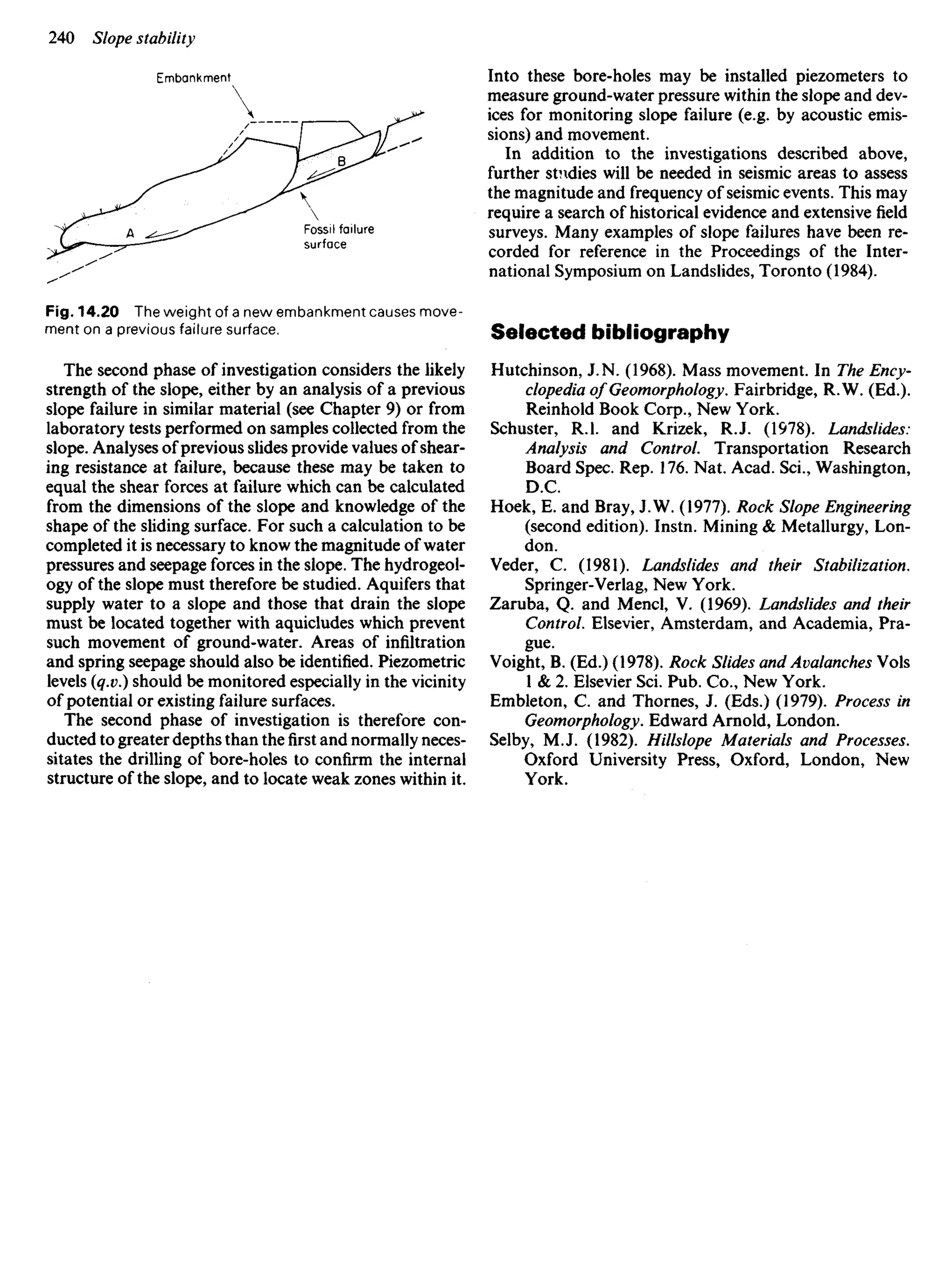
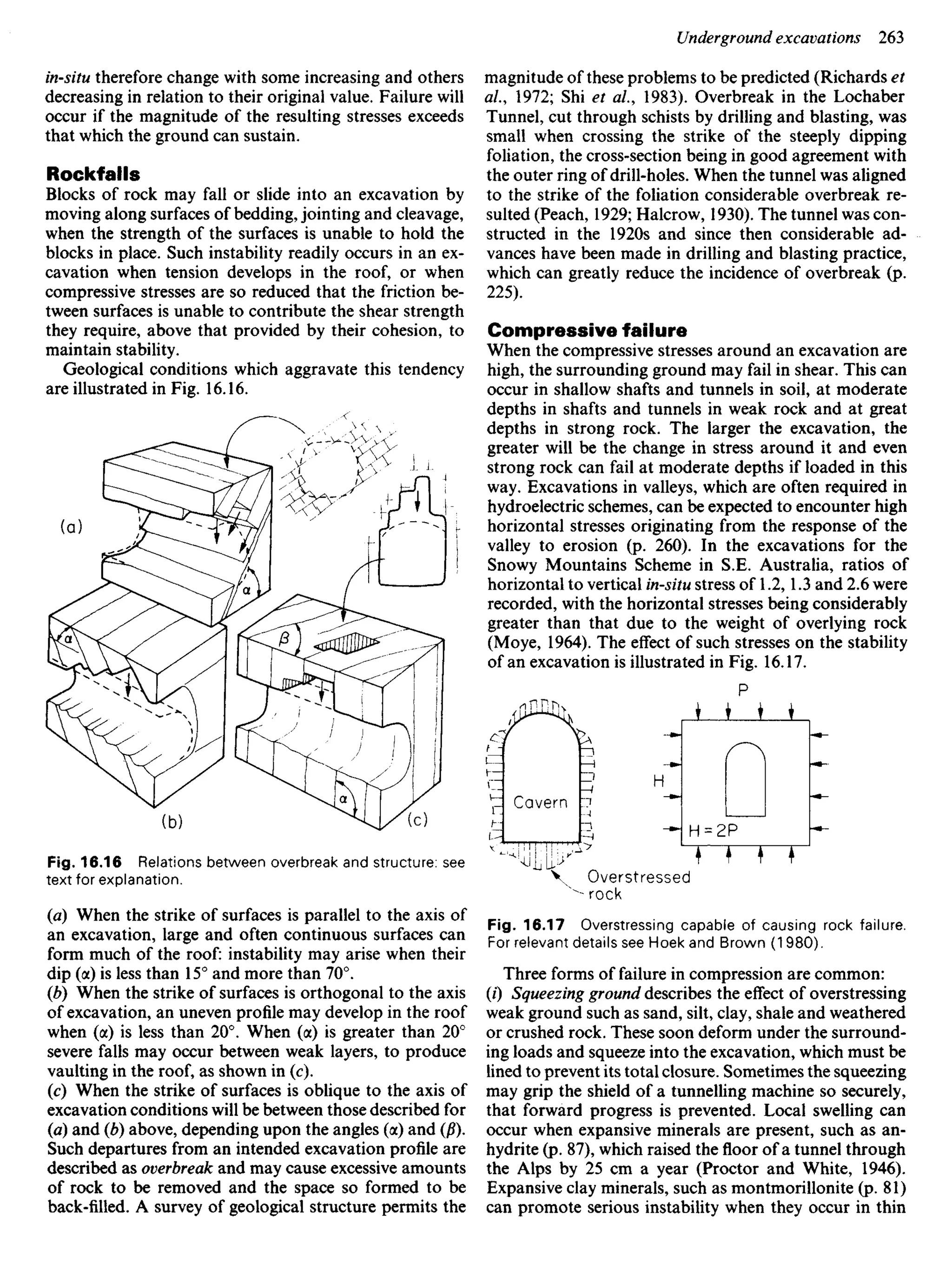
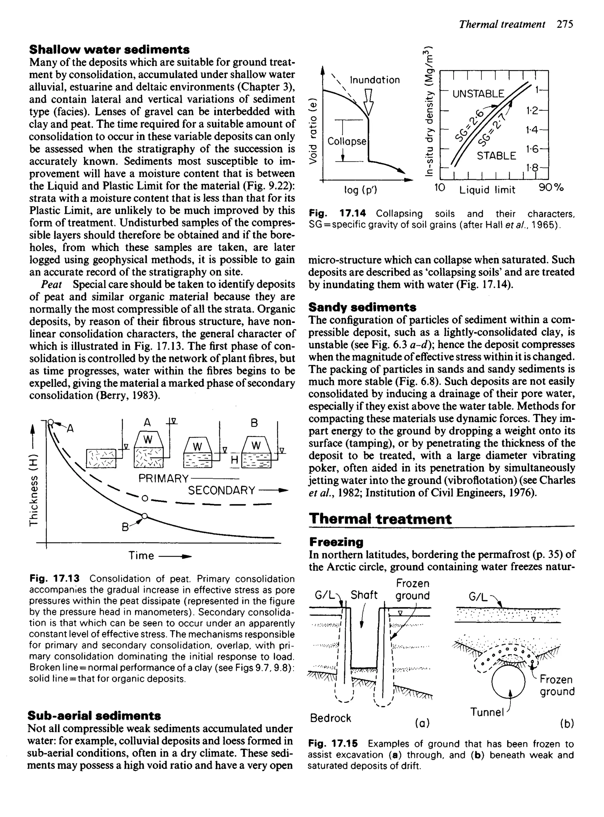
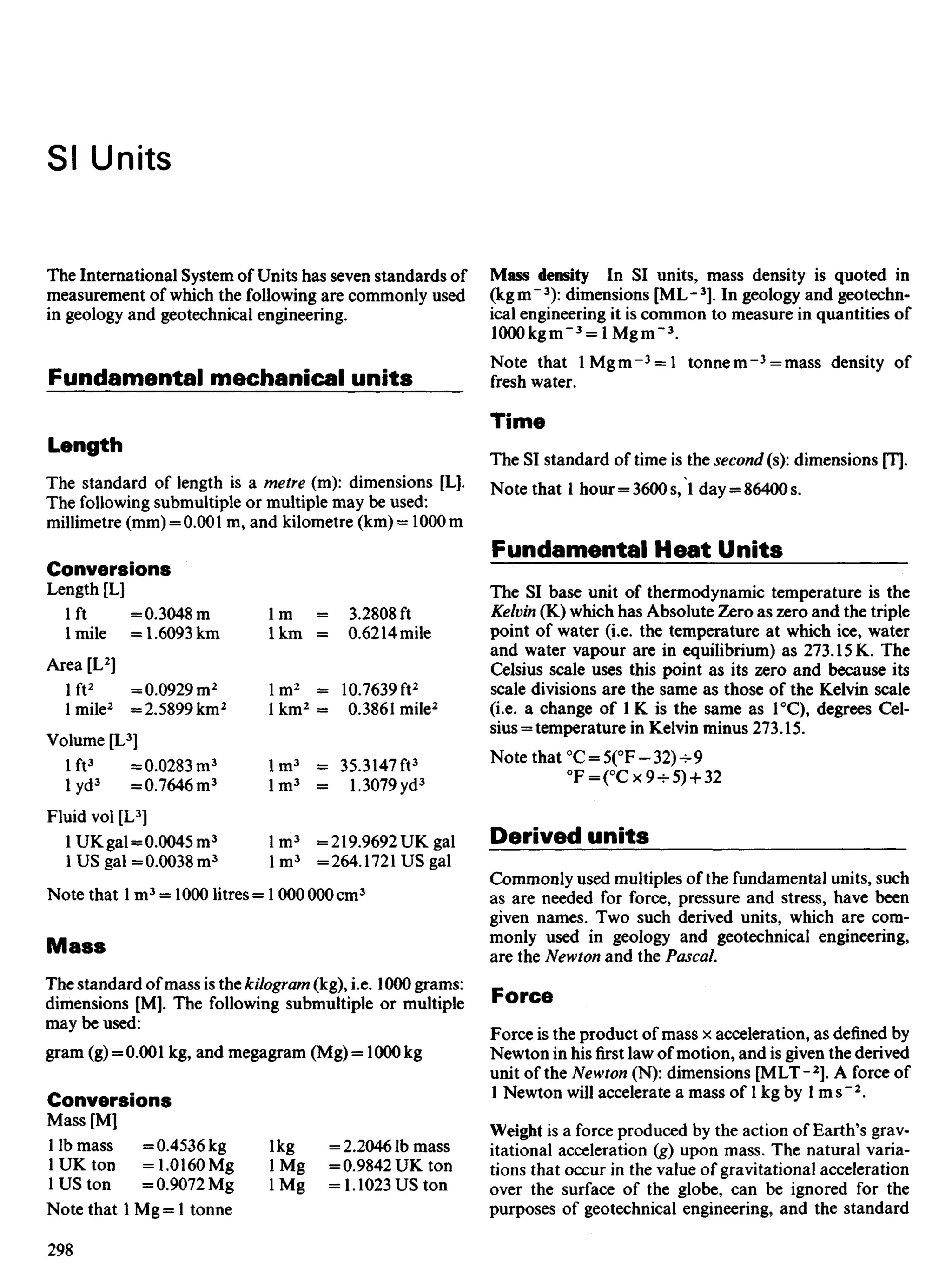
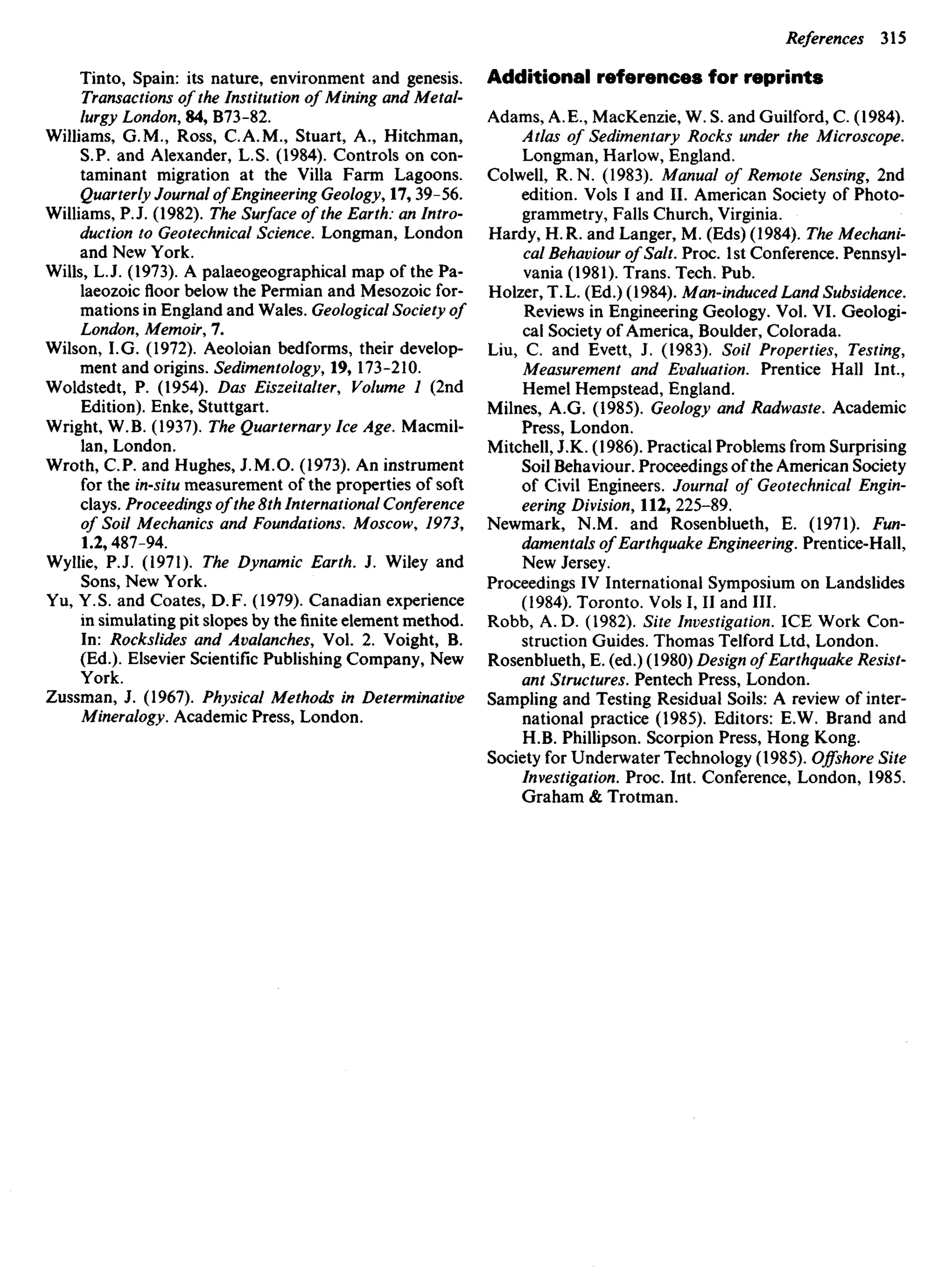
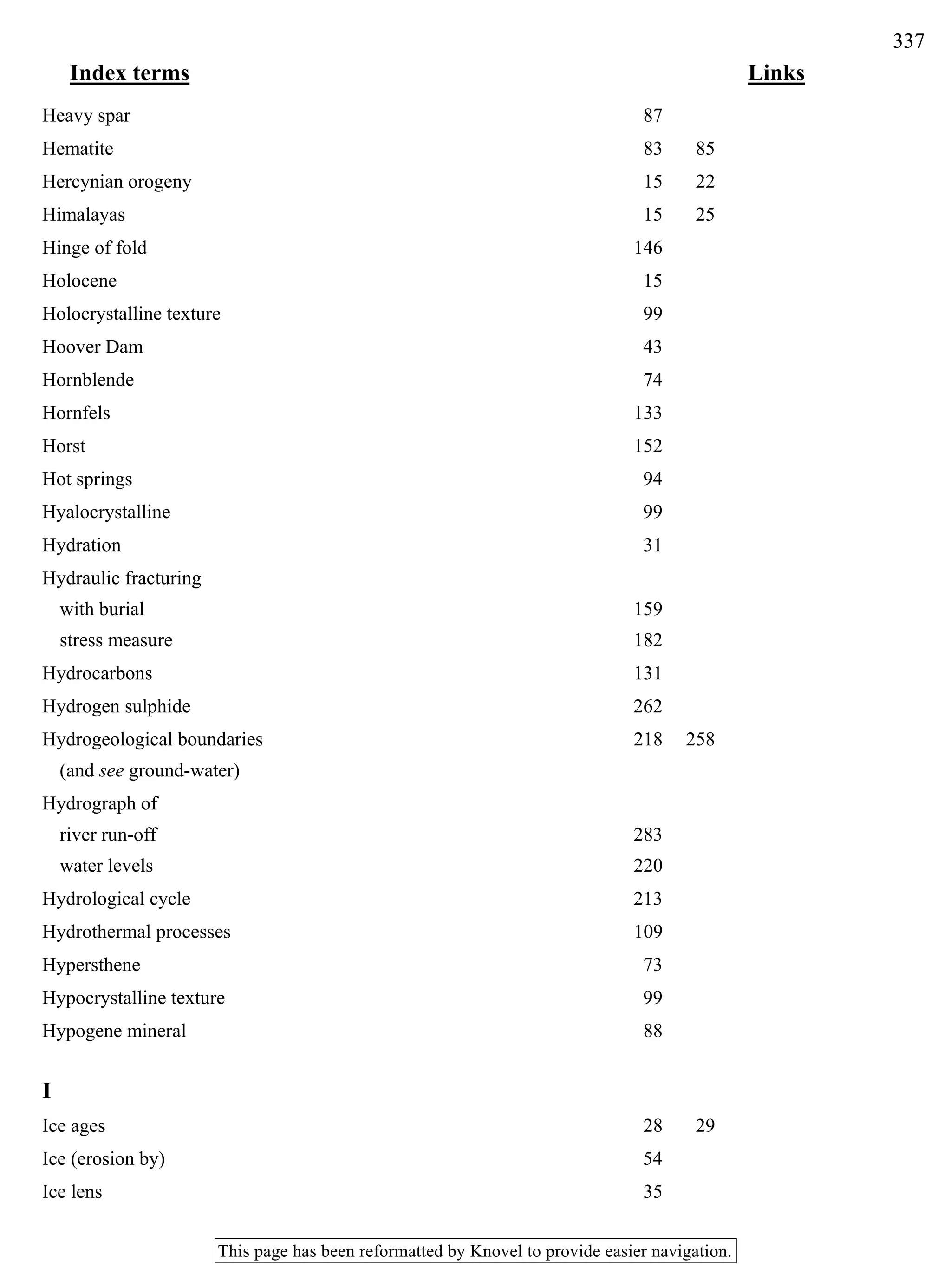
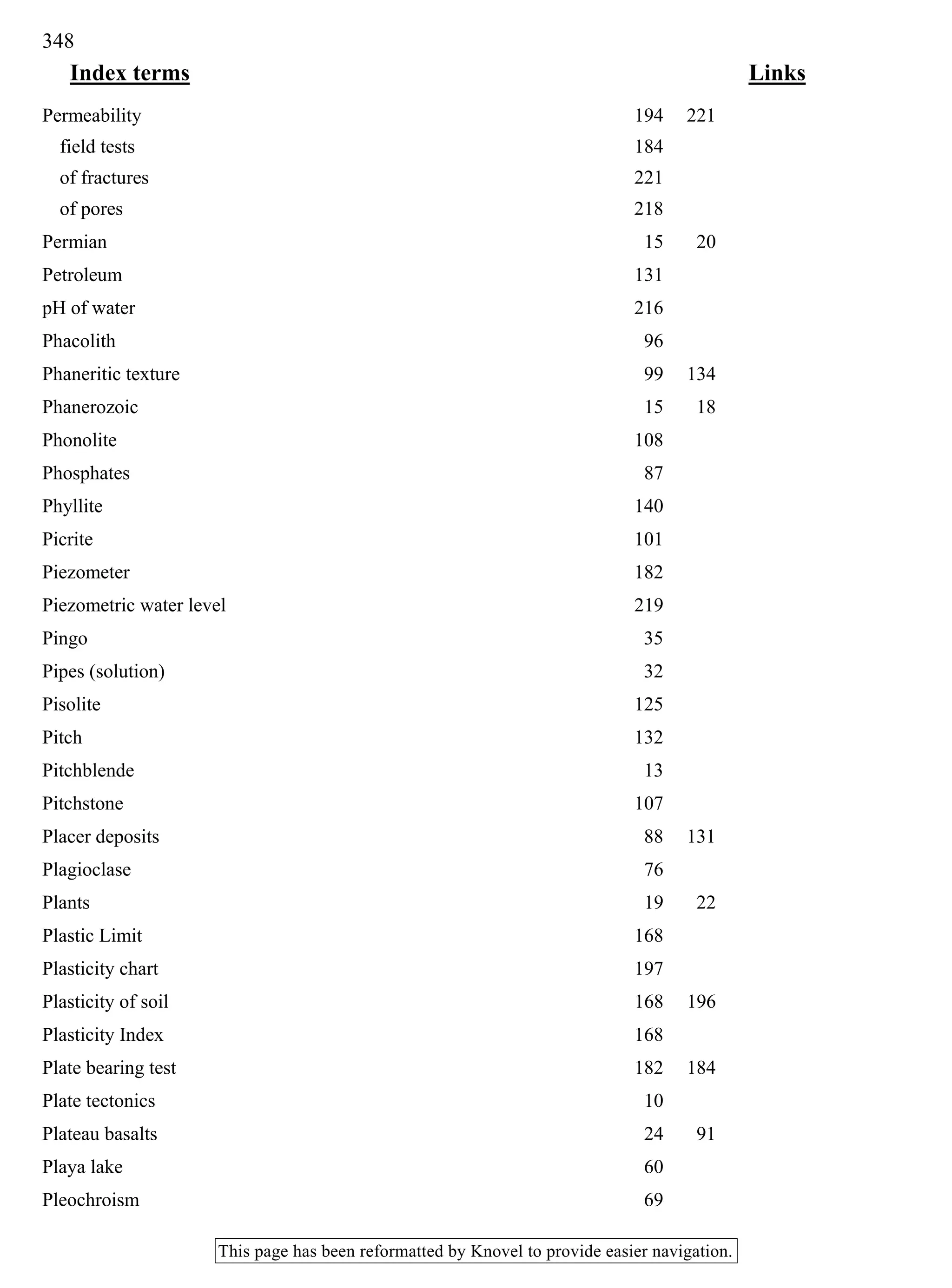
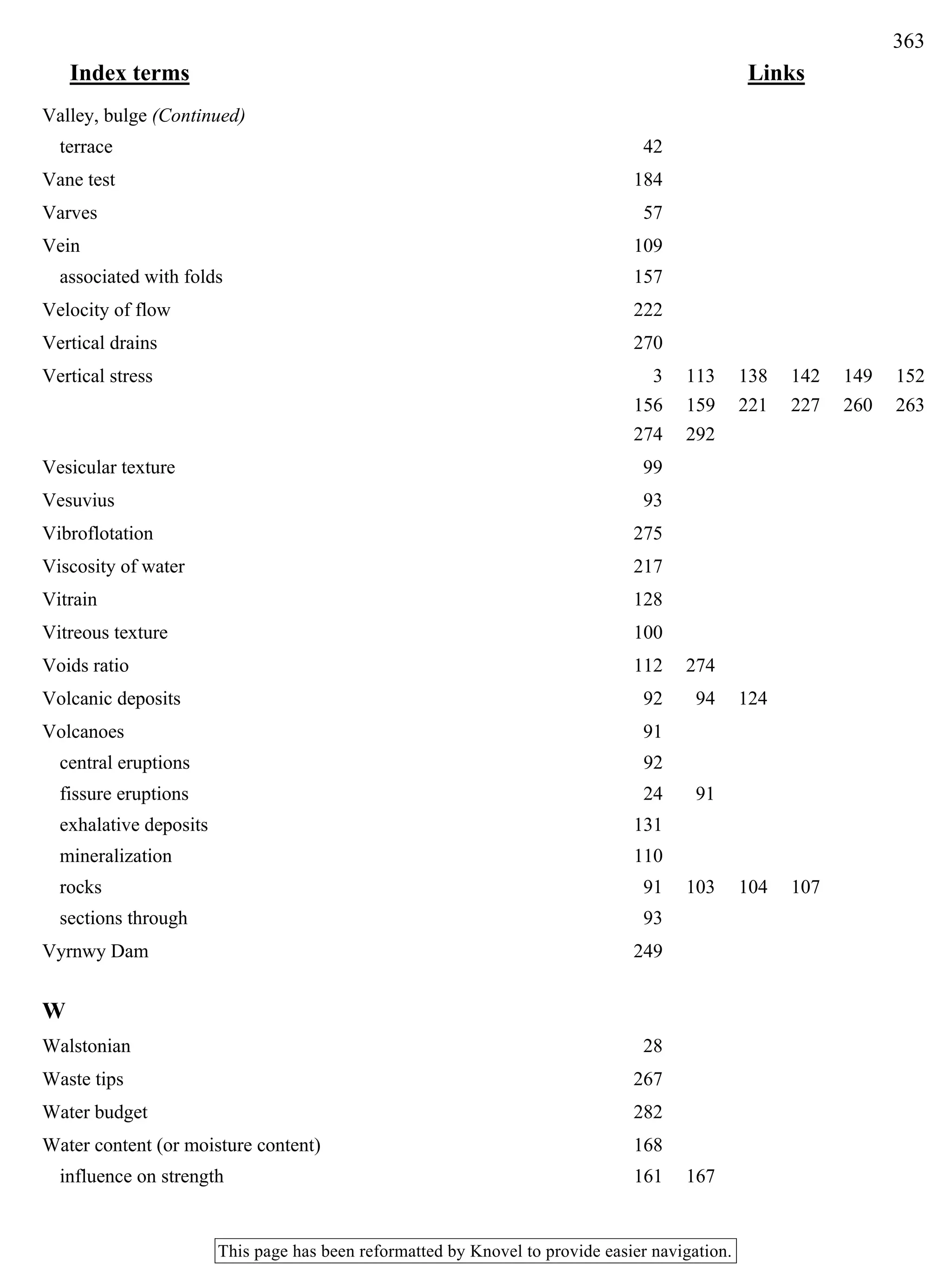
![Table 6.2 A classification for sediments and sedimentary rocks. Sediments listed in lighter print, sedimentary rocks in darker print.
DETRITAL (pyroclastic)
>50% GRAINS OF VOLCANIC'ROCK
DETRITAL (calcareous)
>50% GRAINS OF CALCIUM CARBONATE
1
DETRITAL (terrigenous)
>50% GRAINS OF ROCK & SILICATE MINERALS
Consolidated
as rock
Unconsolidated
raw material
Consolidated
as rock
Unconsolidated
raw material
Consolidated
as rock
Geological
Term
Unconsolidated
raw material
PARTICLES
(orGRAINS)
size
(mm) name
Agglomerate
Volcanic
breccia
X
Tuff
Volcanic bombs &
ejected rock blocks
Fine strands and
droplets of lava
ejected into the
atmosphere
Volcanic ash
Volcanic dust
Conglomerate
Breccia
LU
CJ
Carbonate <
gravel u
Pisolithic c
grit 5
Carbonate "§
grit *
O
CJ
Carbonate H
sand cj z
..^. _l LU
oolitic < Q:
limestone u
<
Carbonate ^,
silts t
Z)
Loess 5
Cement-stone d
Chalk cj
Storm beaten
Colluvium
Coral reef debris
—i Carbonate
> gravel: eg. coral reef
Q£ debris.
O Shell rich beach
! gravel
it
^ Carbonate
< sand. eg. shelf and
^ beach
T
^] Carbonate
Zn Silt: eg. lagoon silt
• Desert Dust
>. Carbonate
-J mud
Comglomerate
Breccia
Tillite
Conglomerate
Grit
Sandstone
(arkose, grey-
wacke, and
other varieties)
Loess
Siltstone
Mudstone &
Shale
E
CO ȣ=
LU y
II
< CO
ZD ^
<cj I
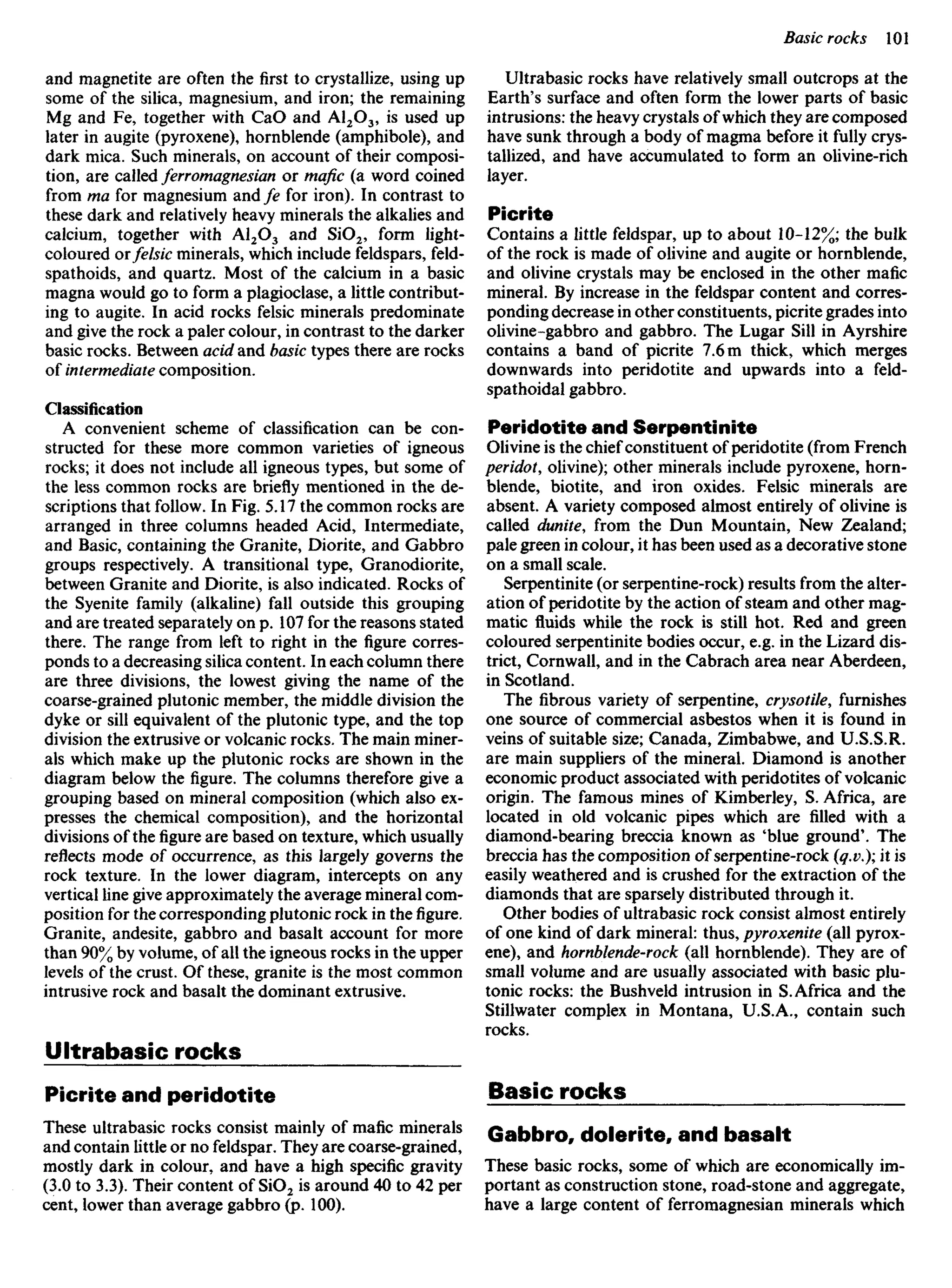
CO "co
O .E
CC
<
Storm beach
Colluvium (scree,
or talus)
Glacial boulder beds
1
Coarse-alluvium
(e.g. wadi)
LU
<
QC
Fine-alluvium
— — Deltaic grits
^ and sands
Z
<
1 Sand beach
-X- Desert sand
f & dust
-i Estuarine
00
silt
j_ Glacial silts
T & clays
-i clay
CJ
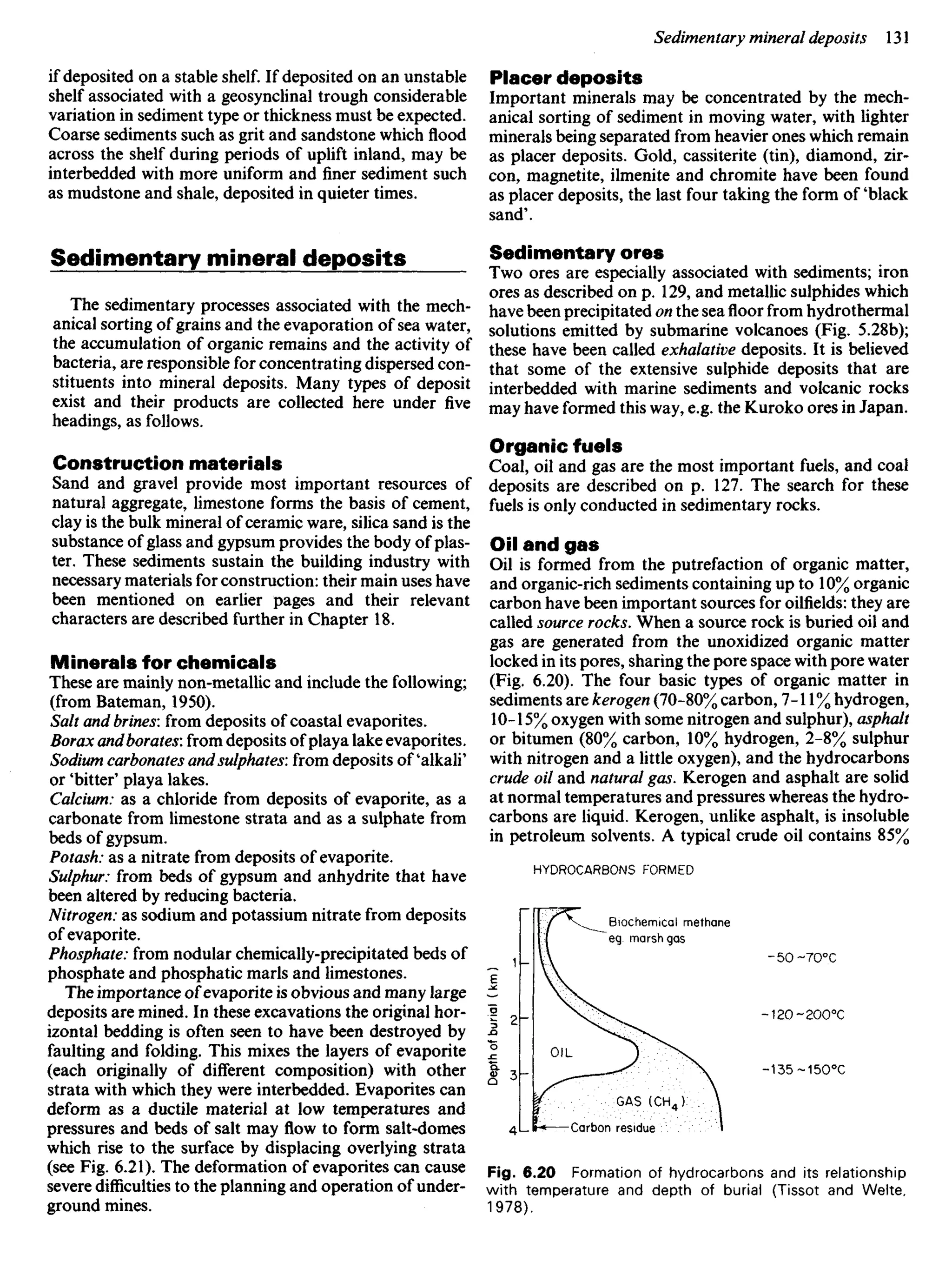
I ooze
Boulder
Cobble
Pebble
Granule
Sand
Silt
Clay
200
4
2 _
0.002](https://image.slidesharecdn.com/ageologyforengineersseventhedition-240123054612-a0c16209/75/A_Geology_for_Engineers_Seventh_Edition-pdf-100-2048.jpg)

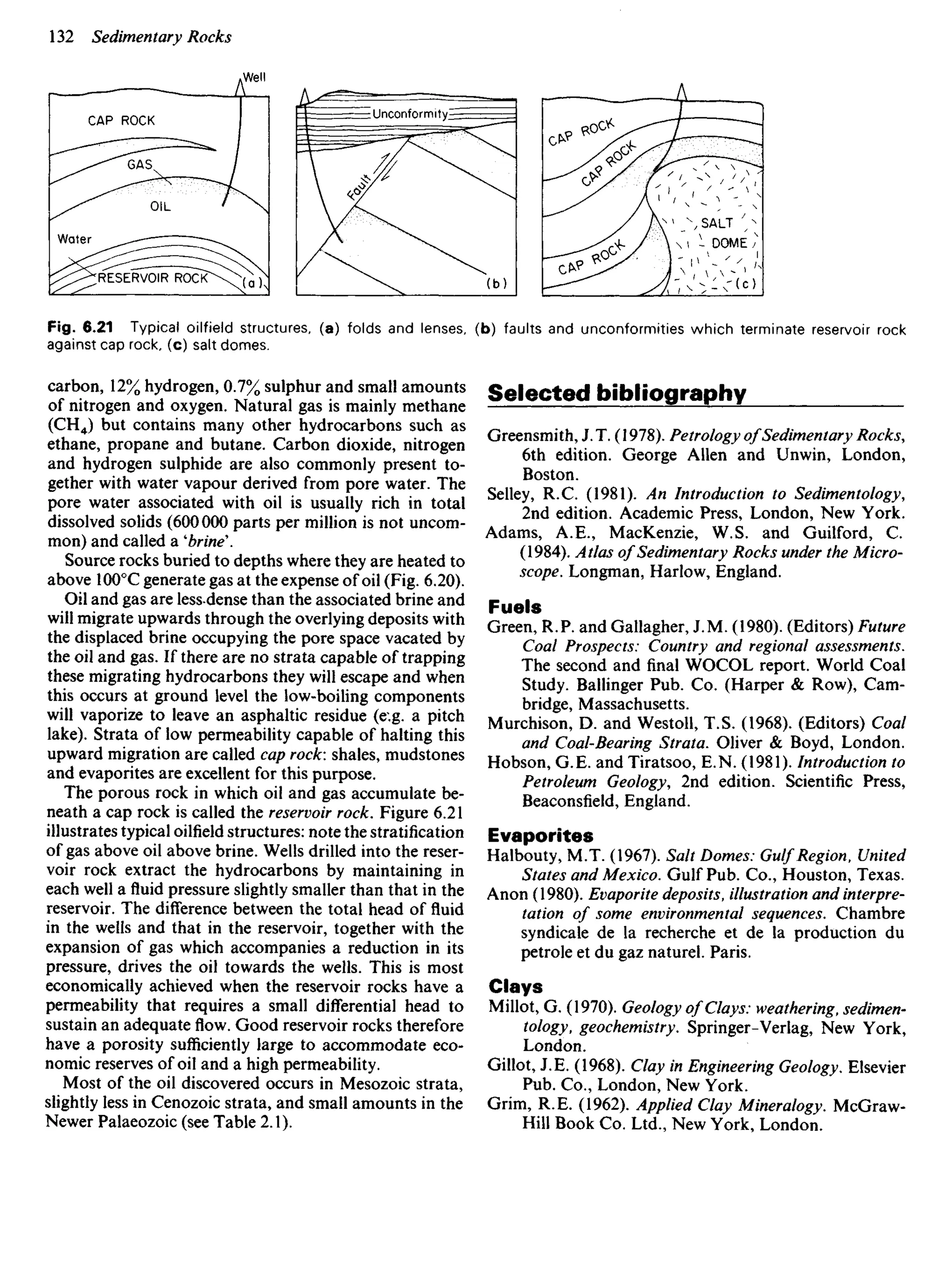
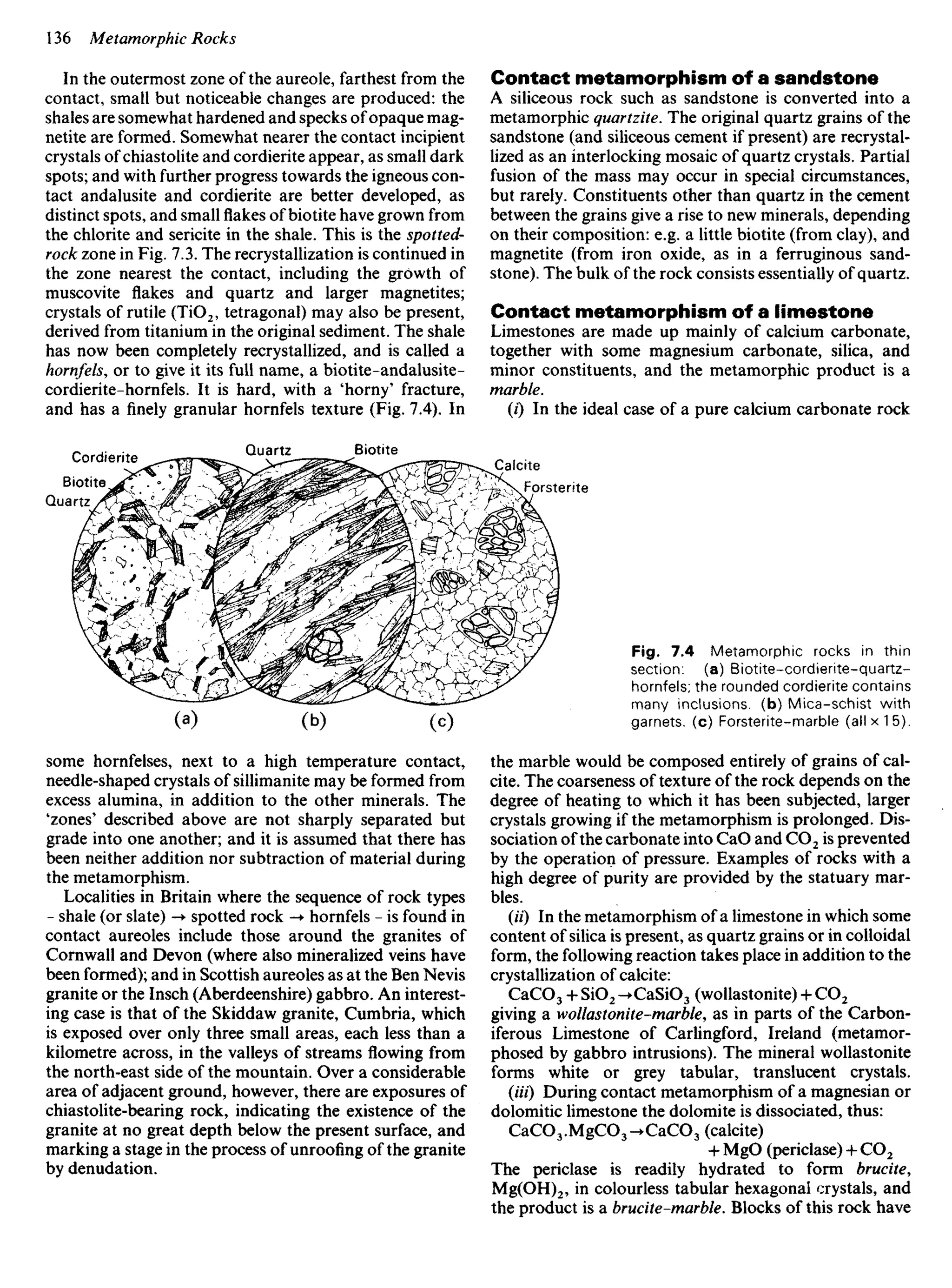
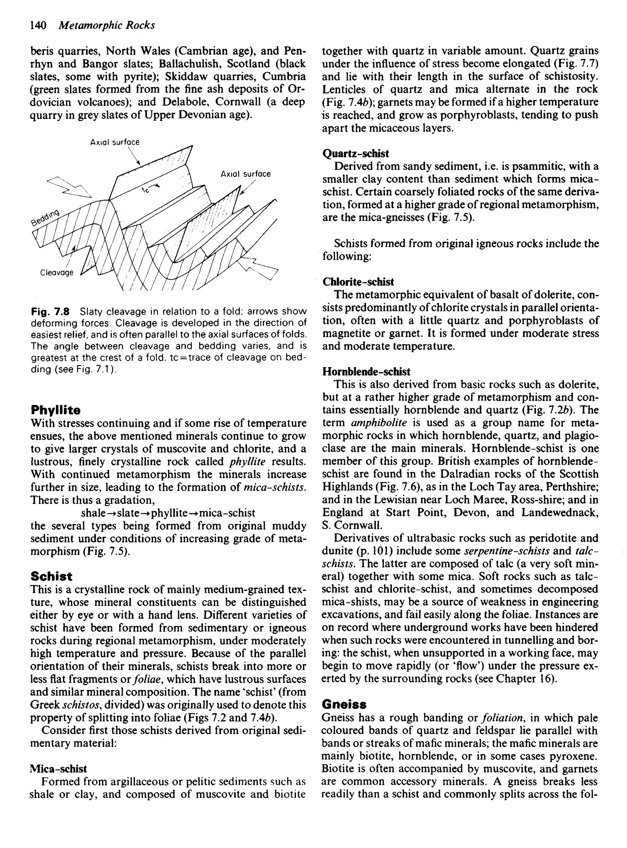


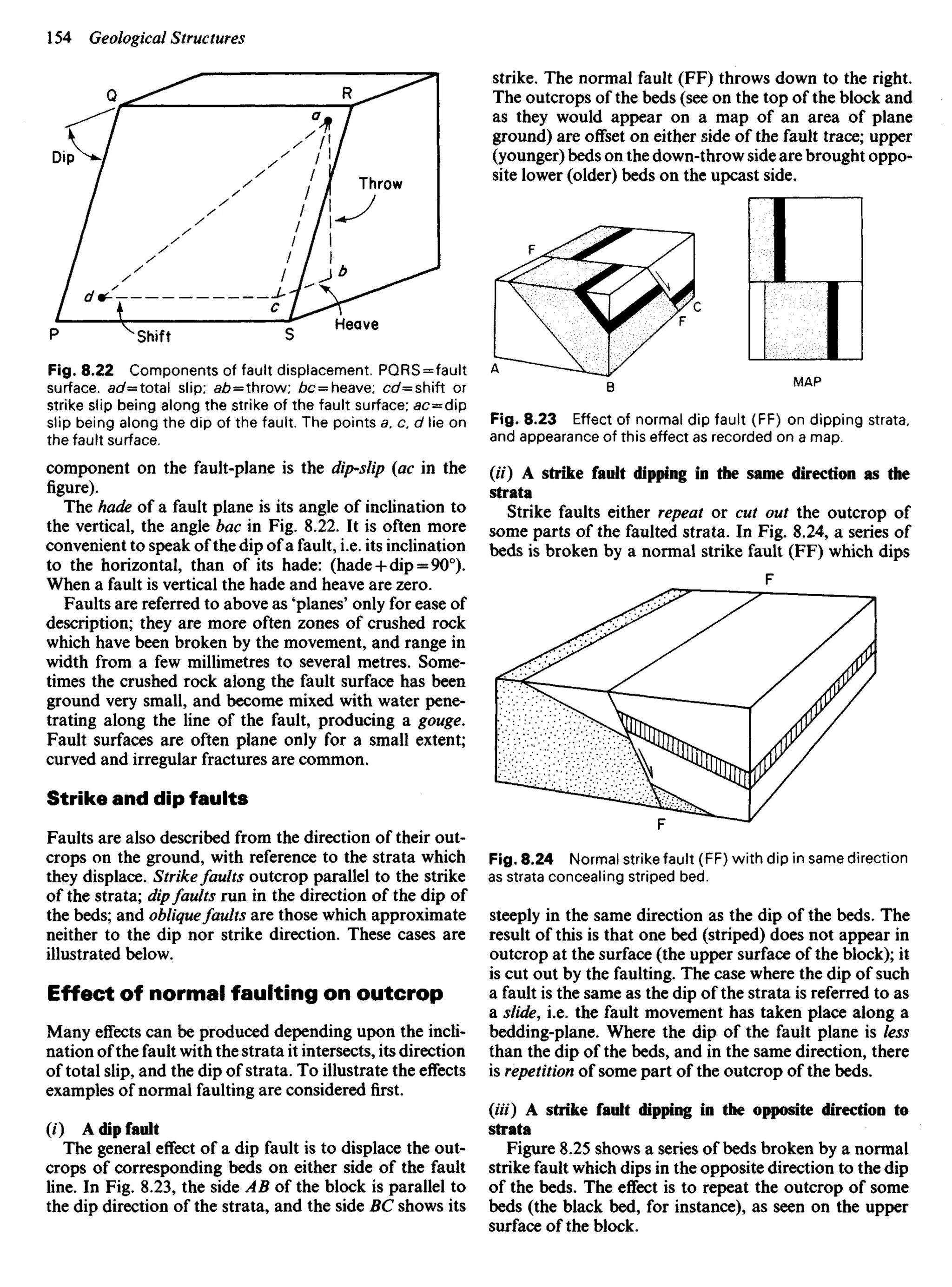

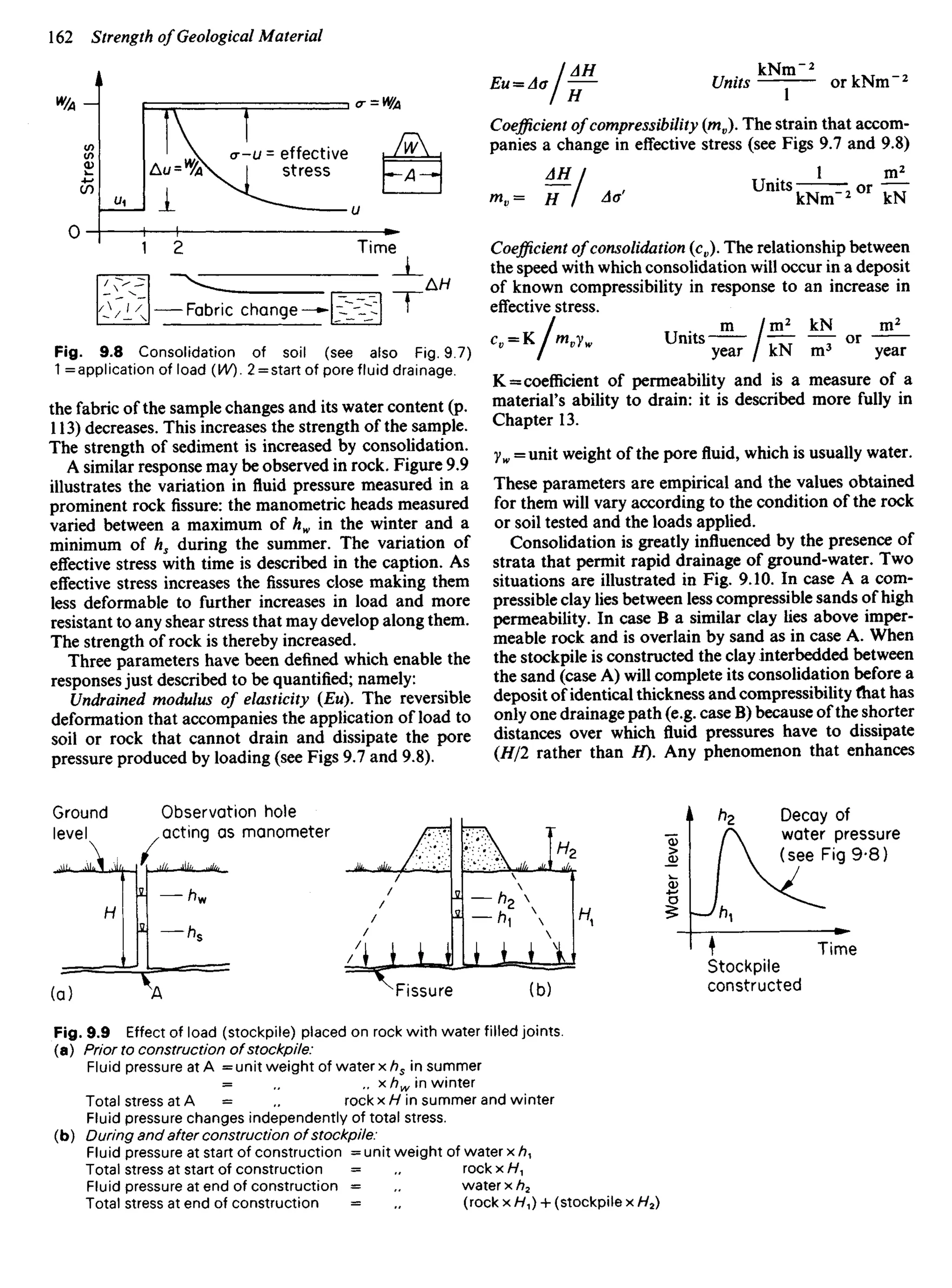
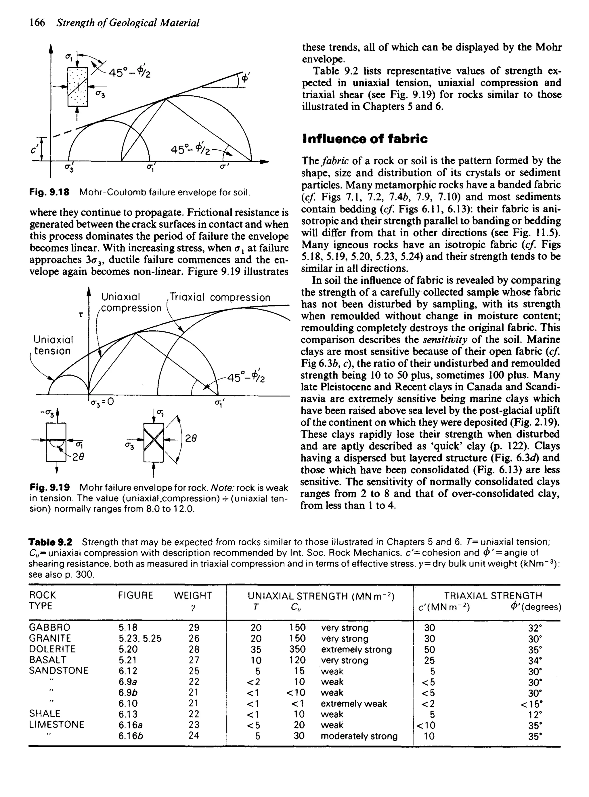
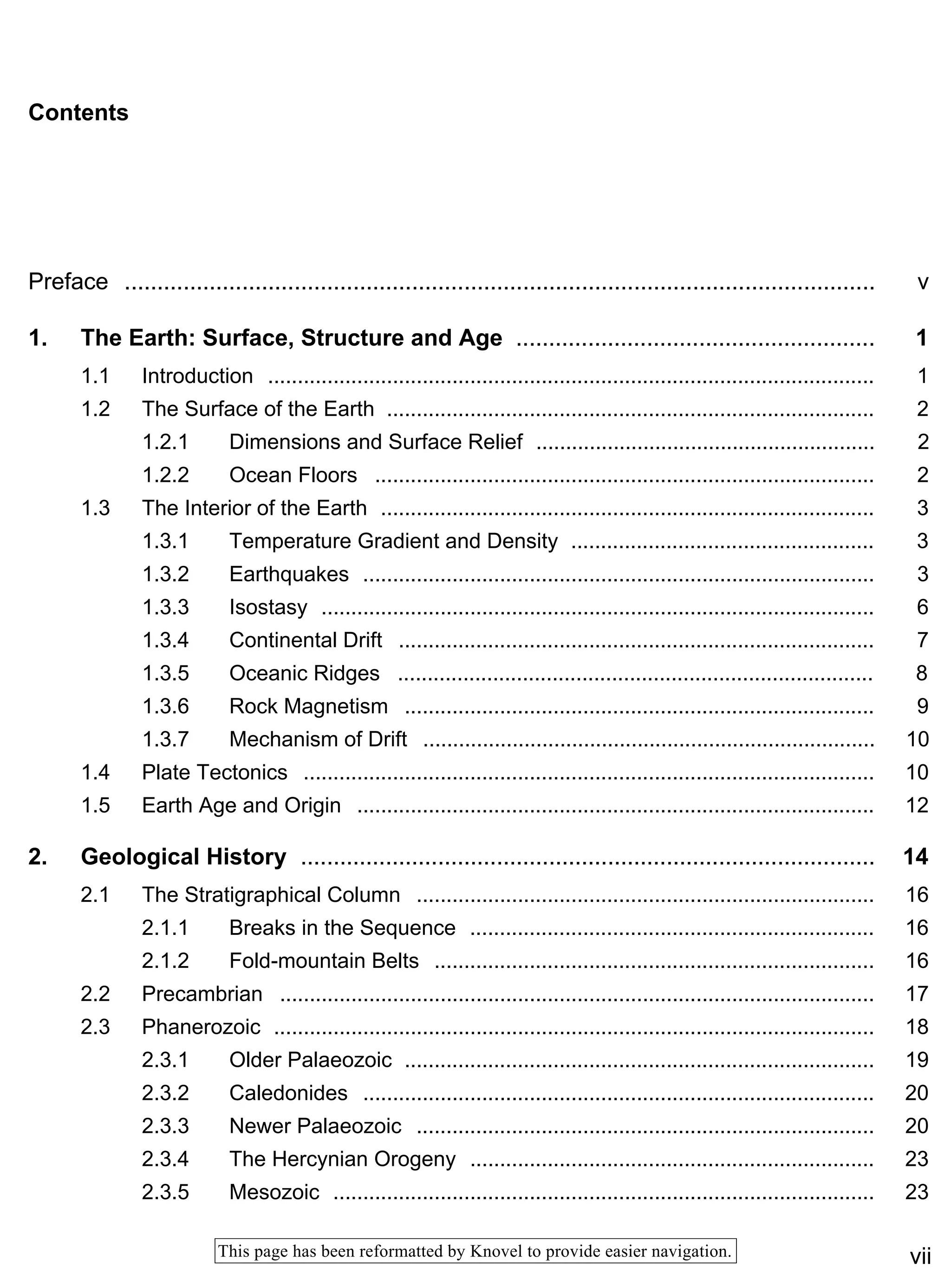
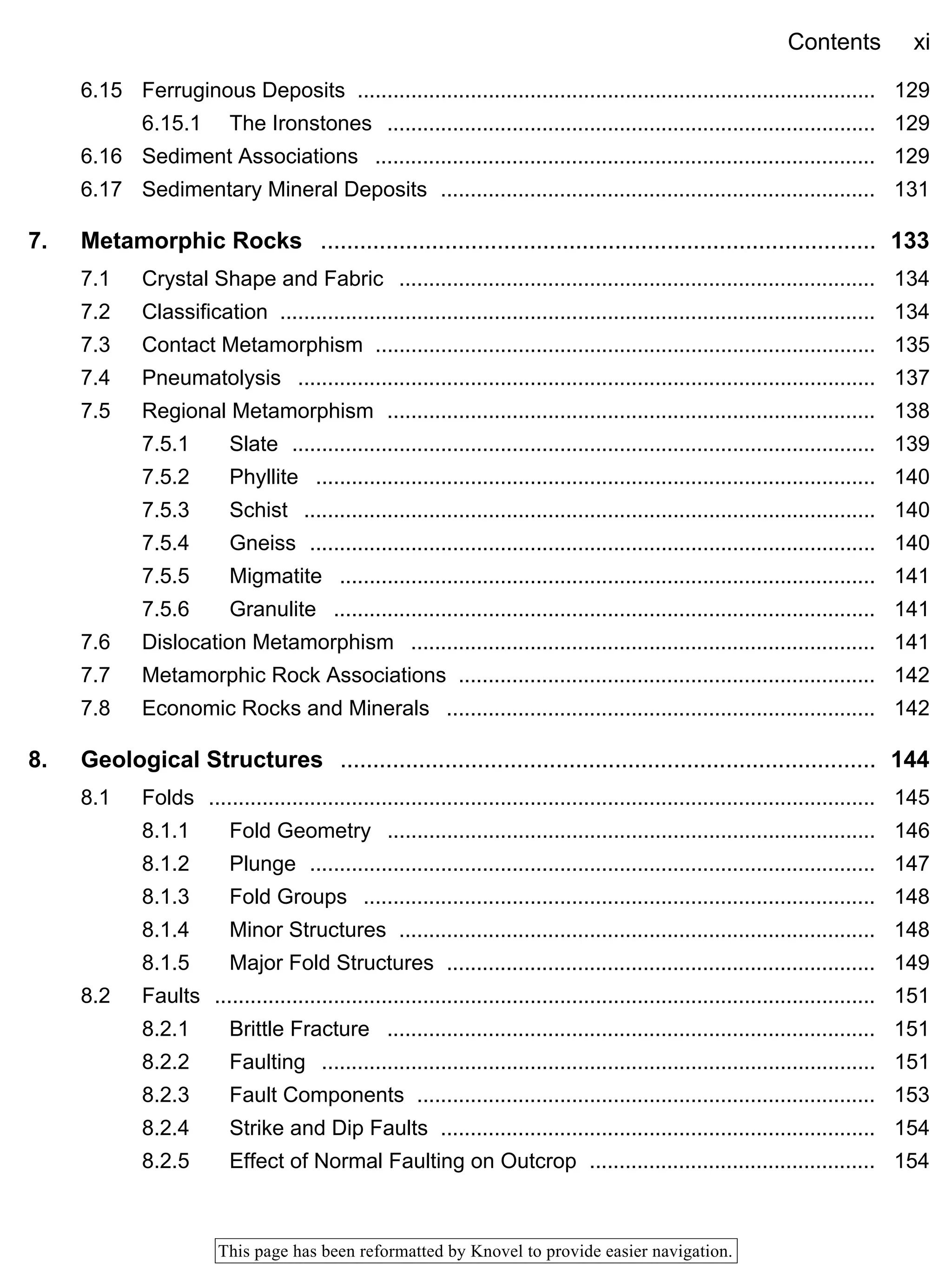
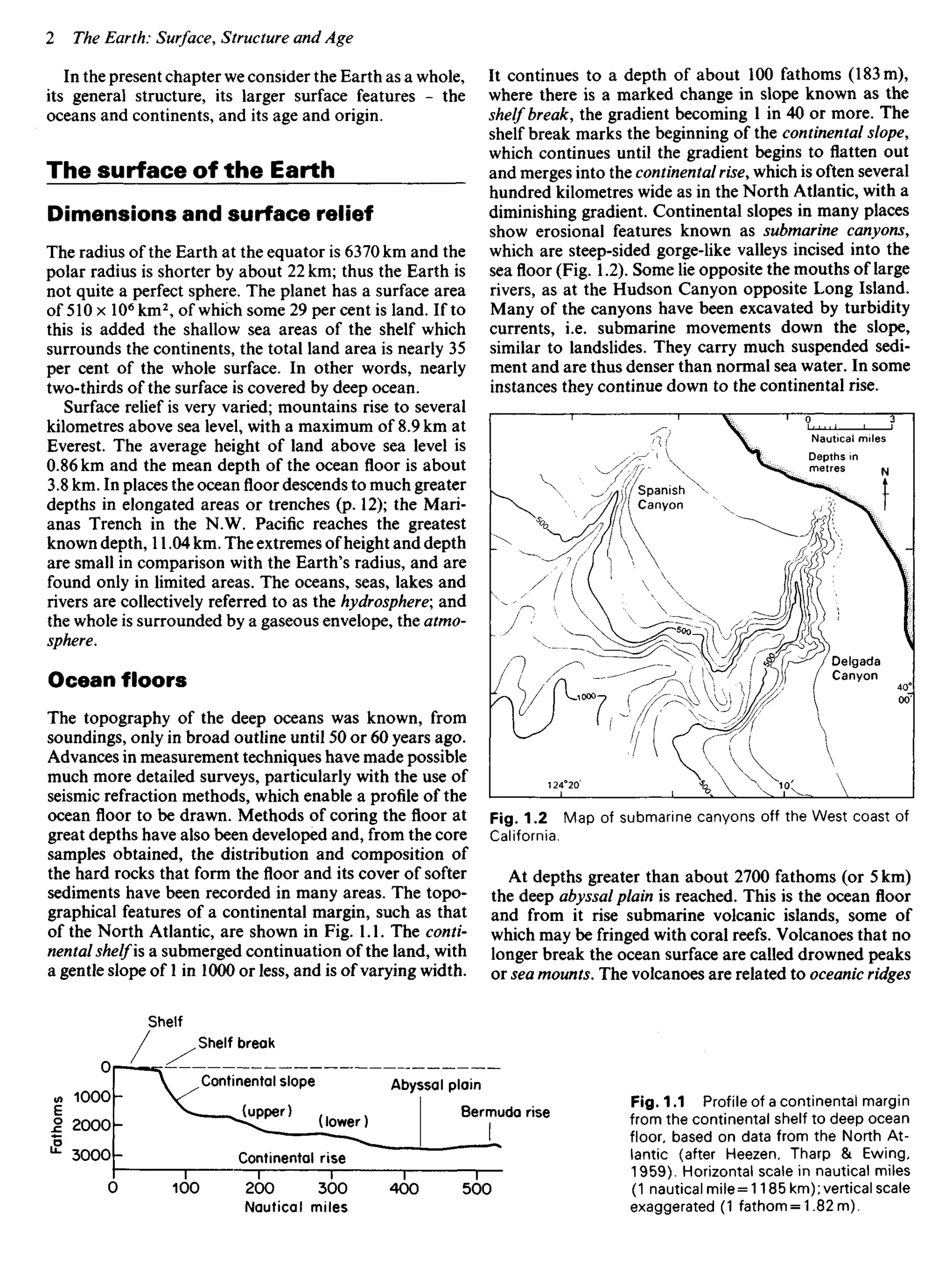
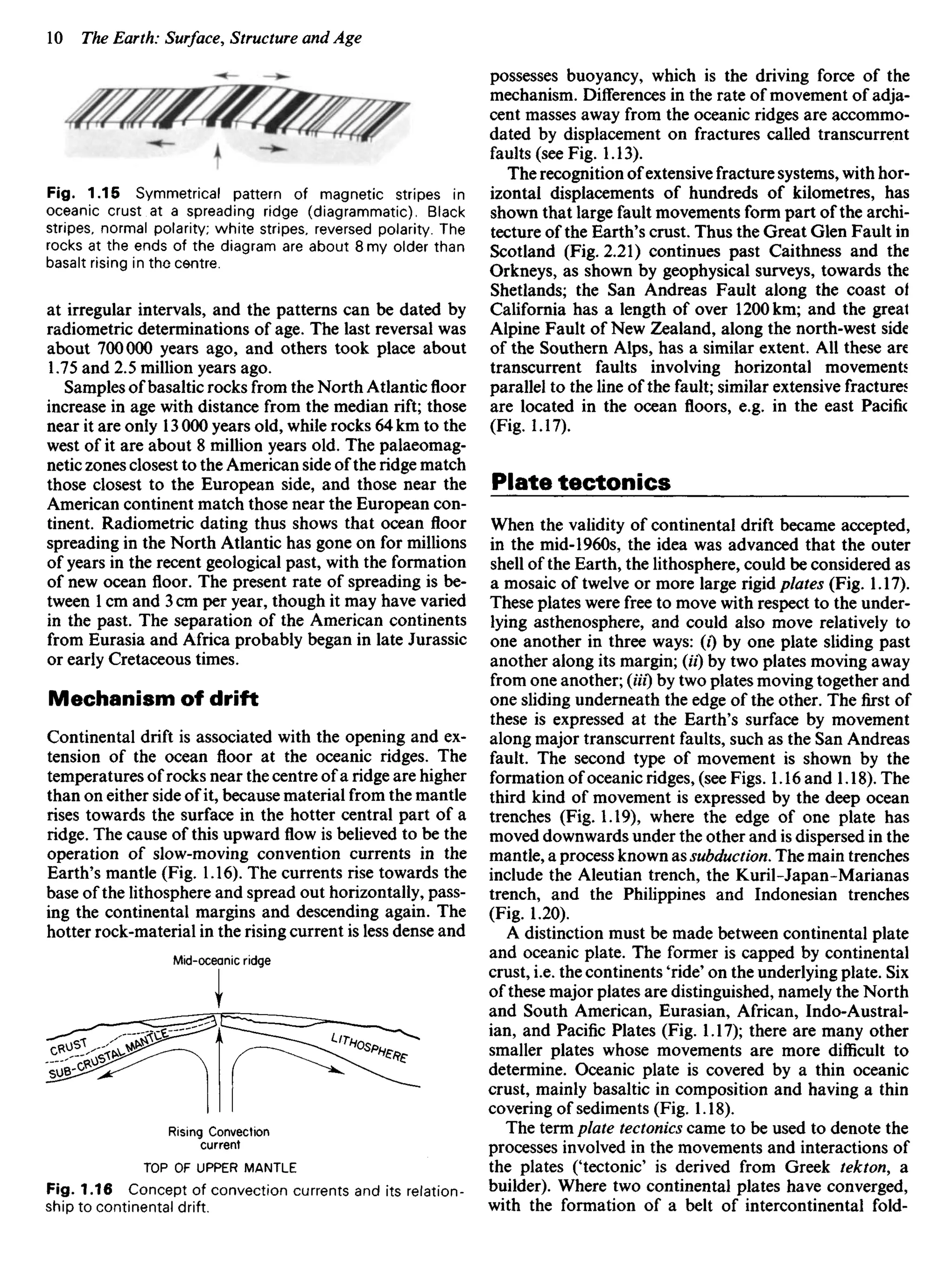
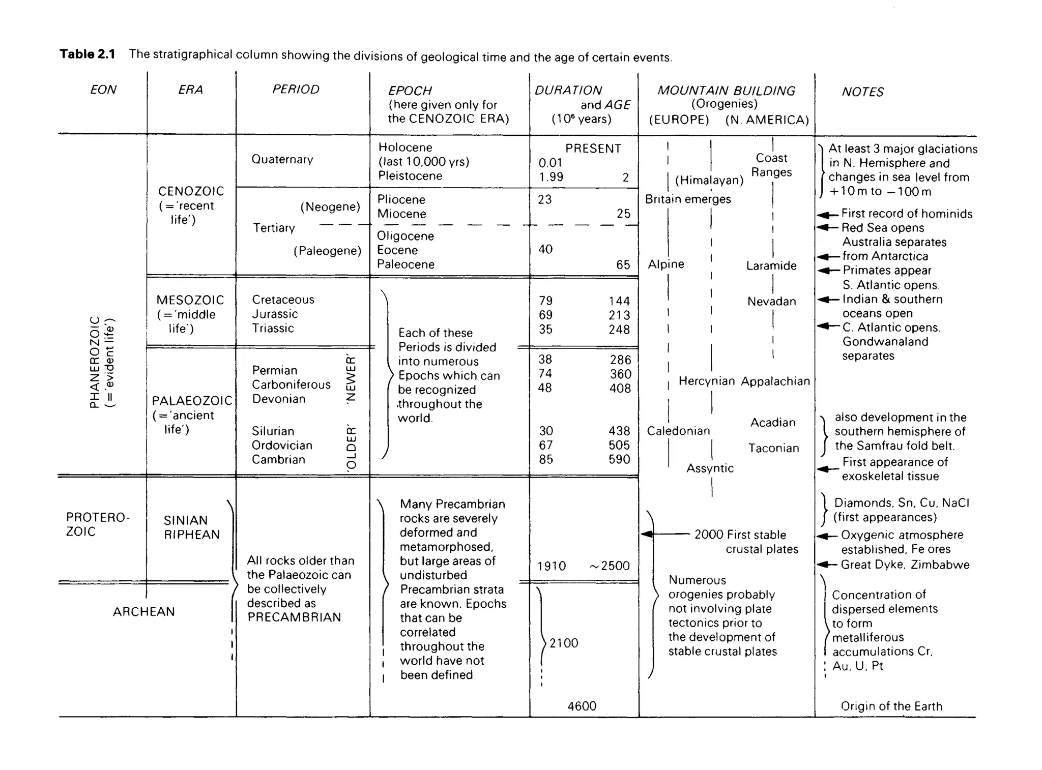
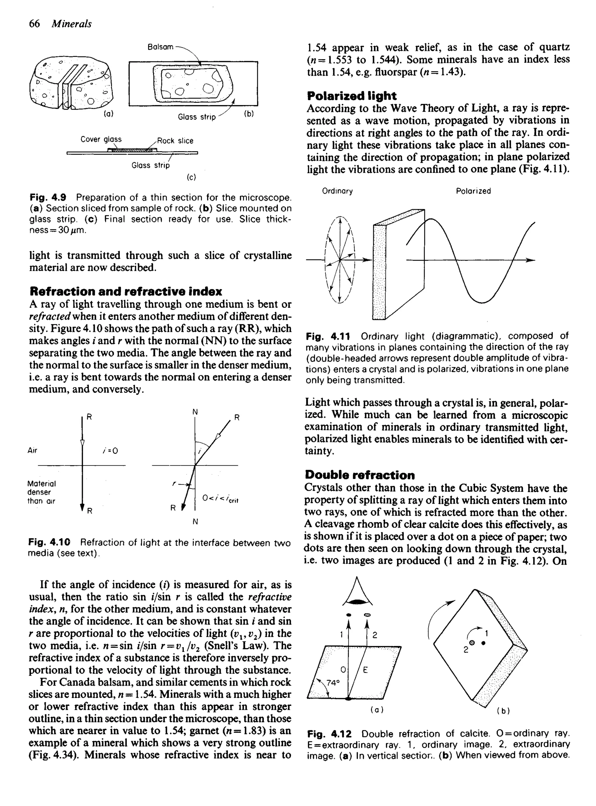
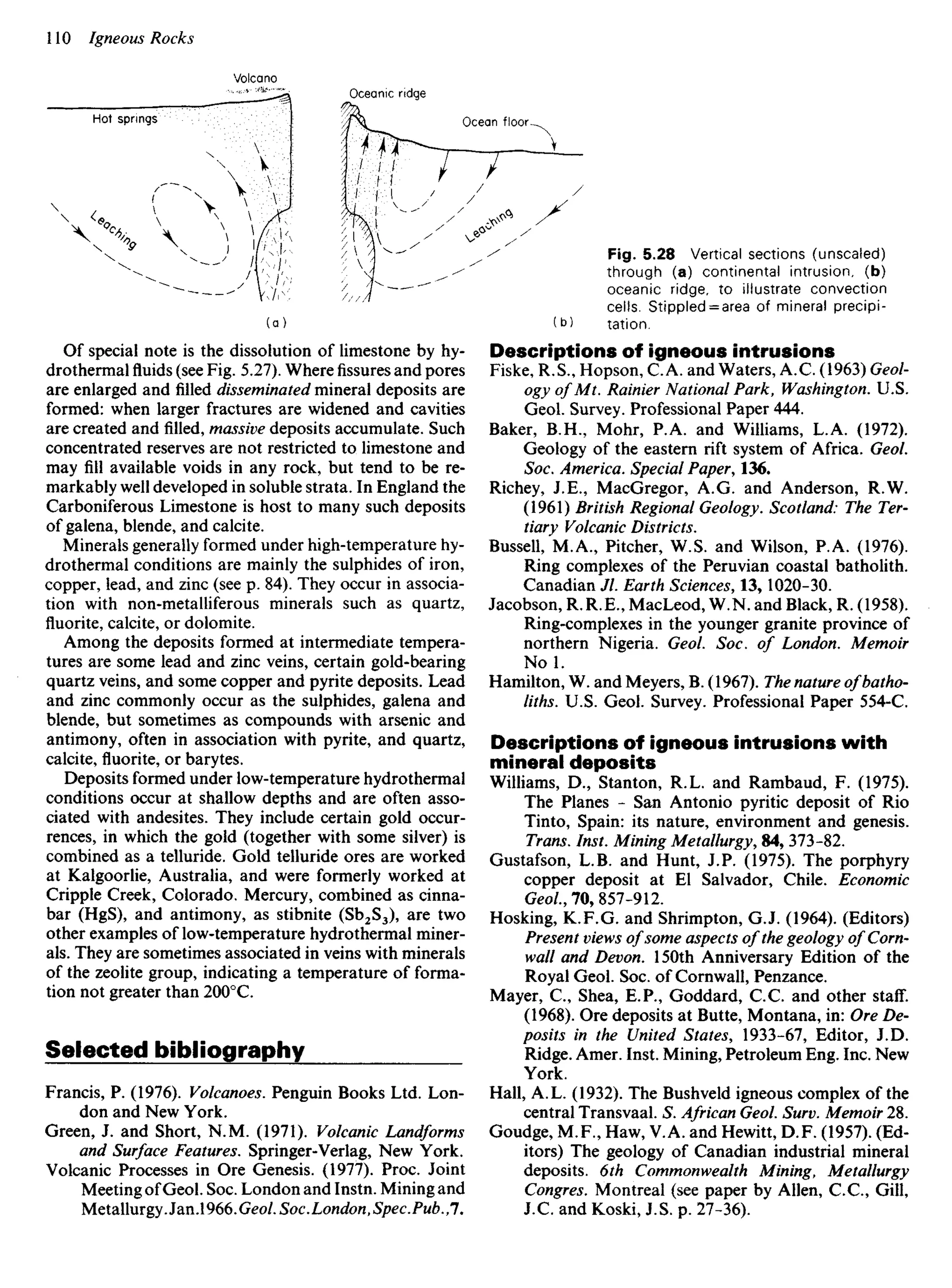
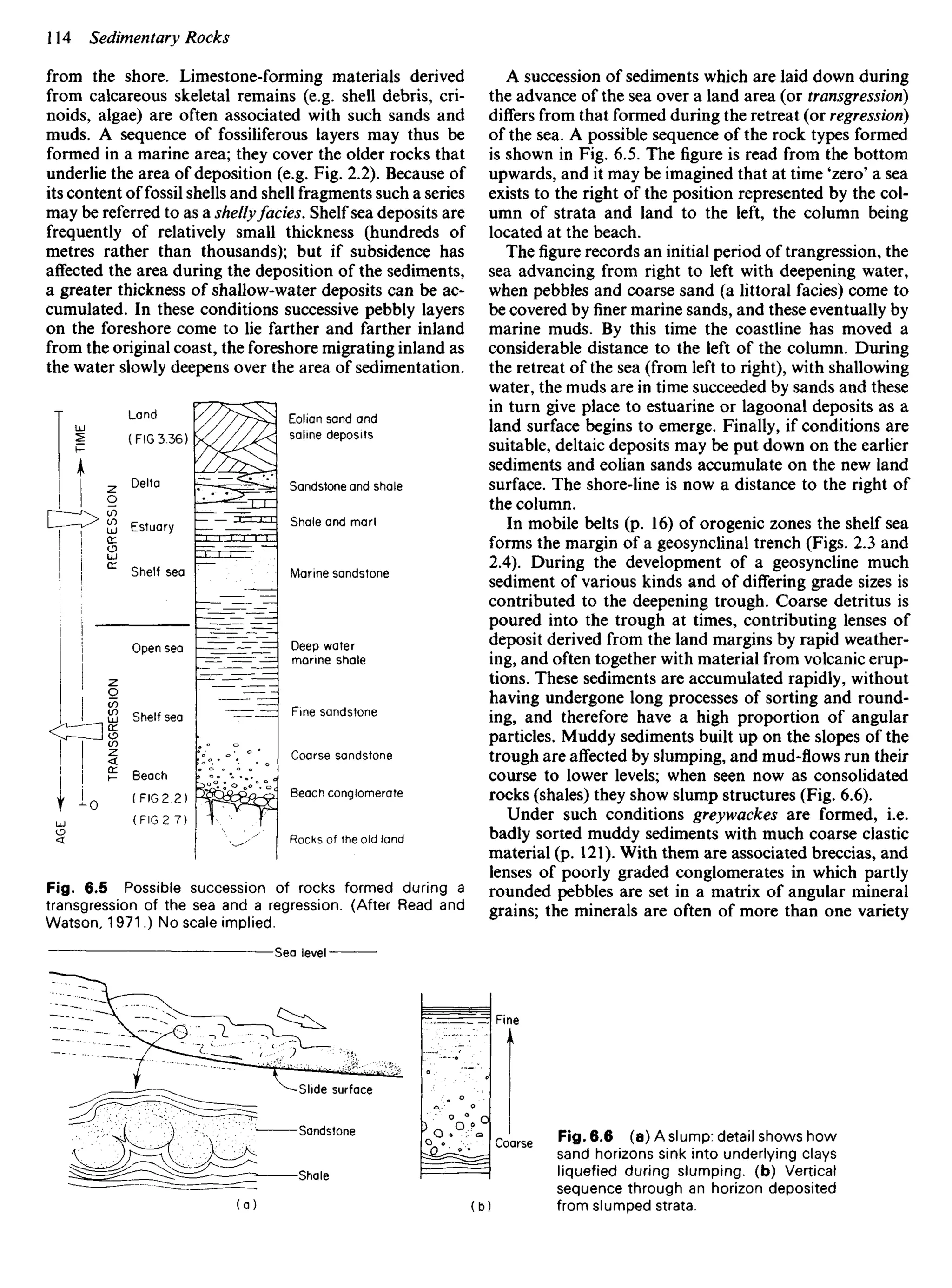
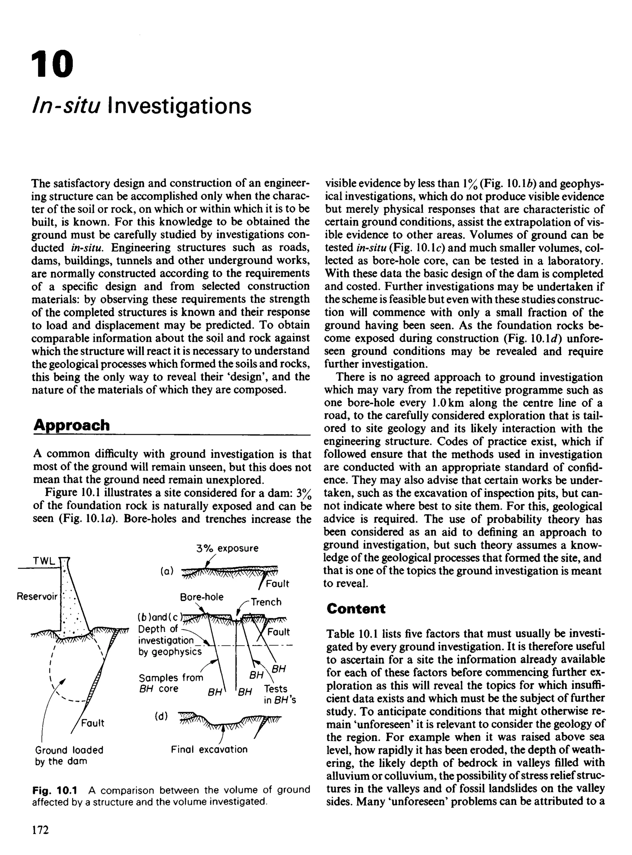
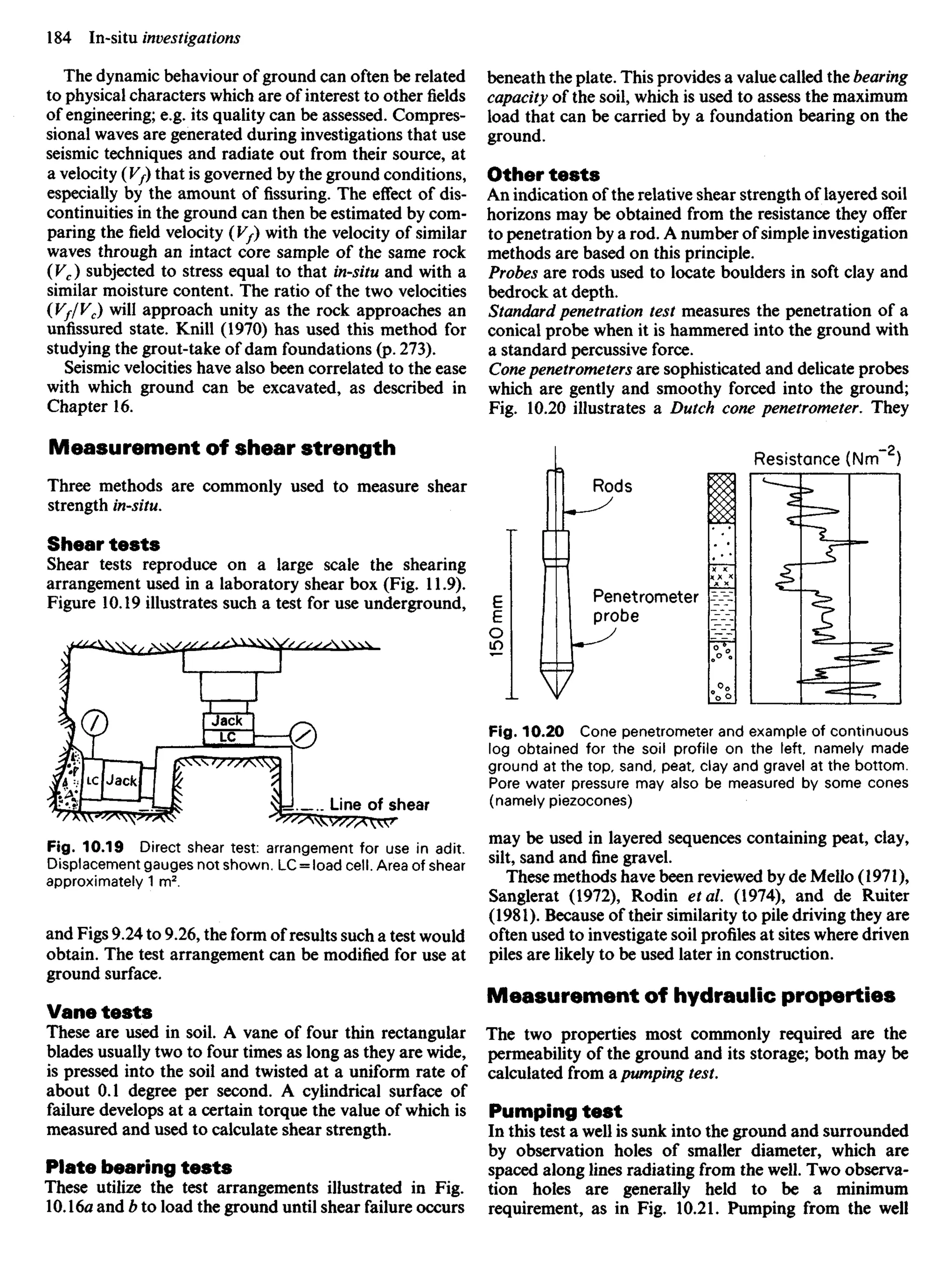
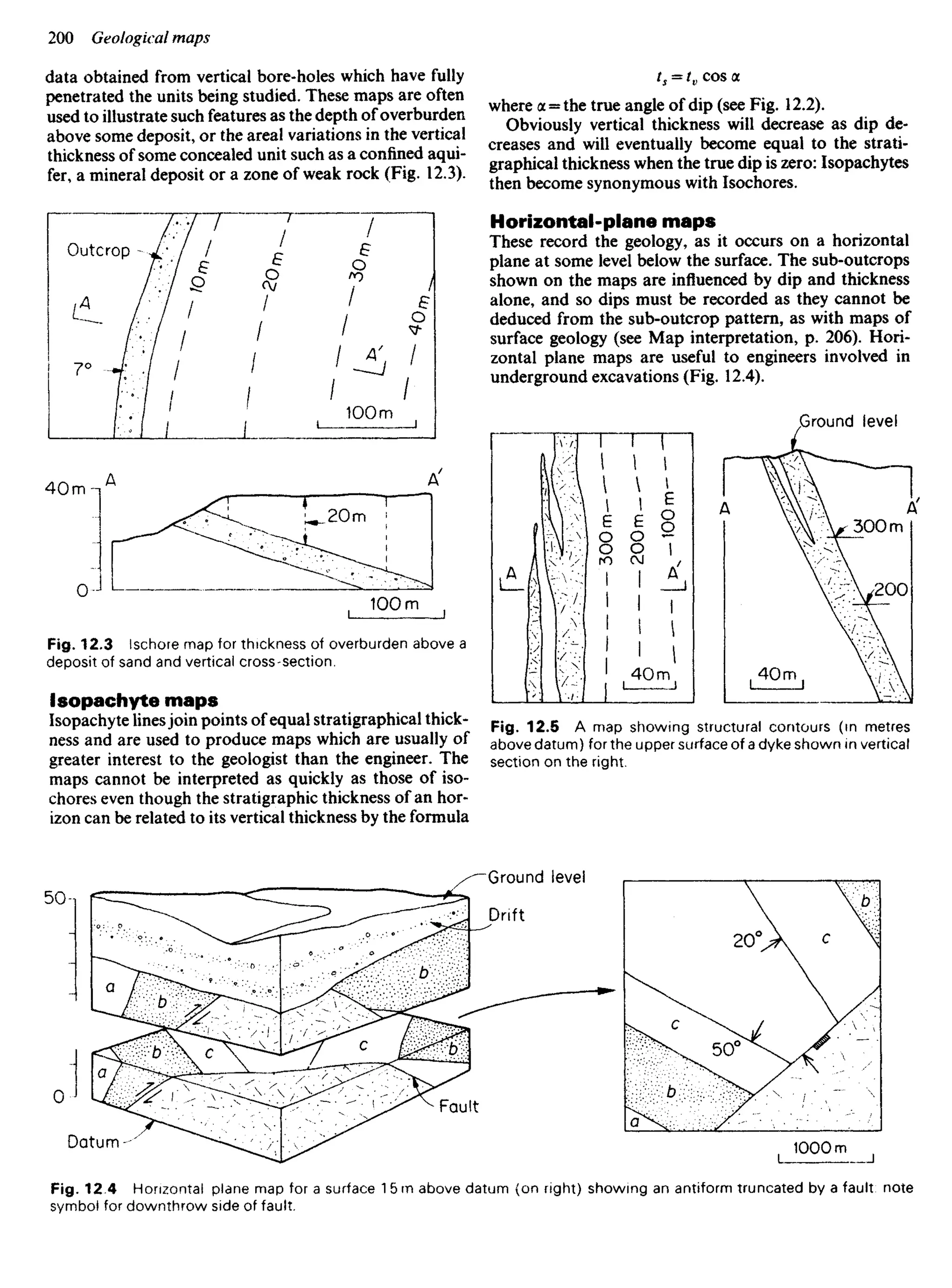
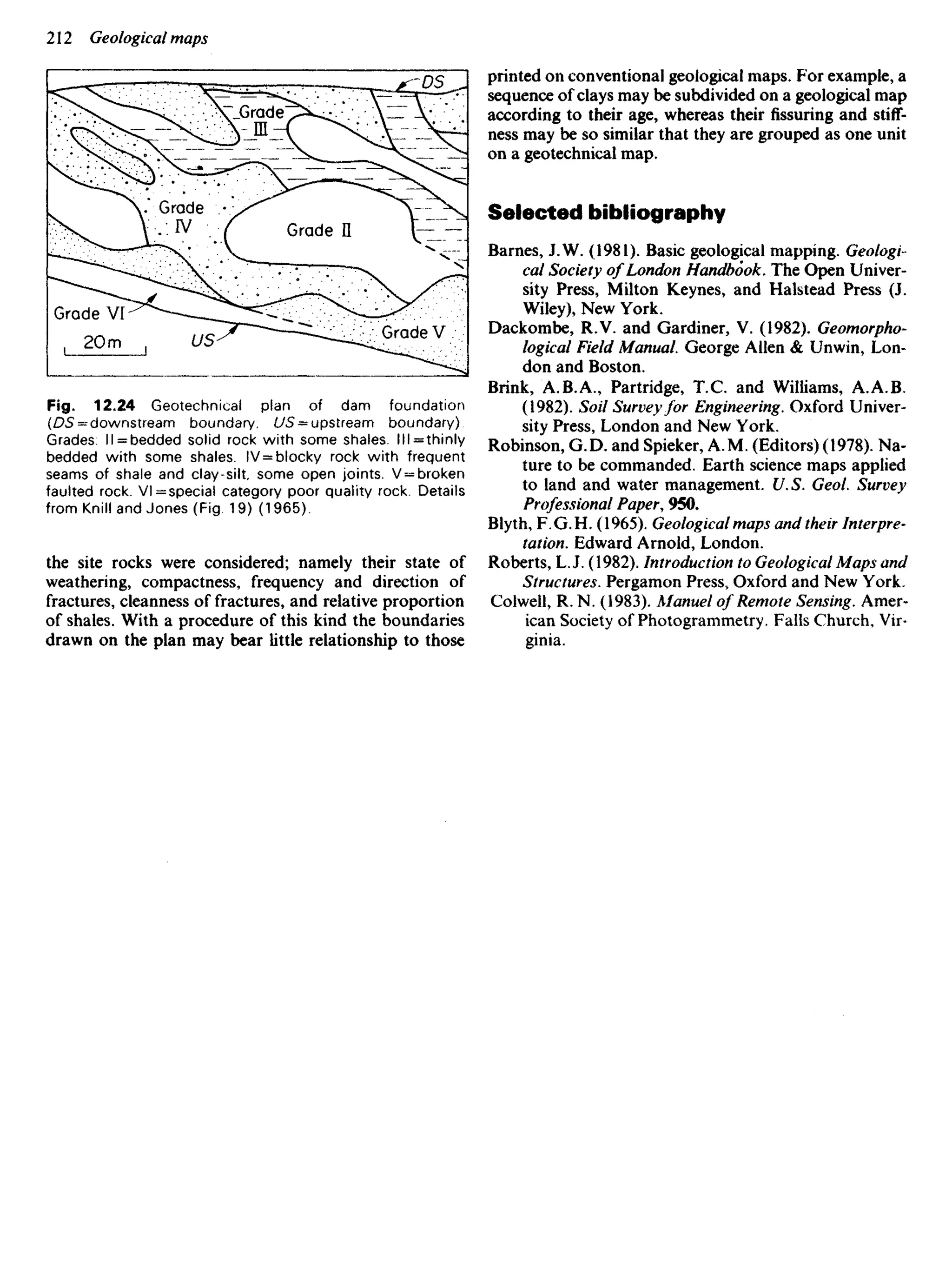
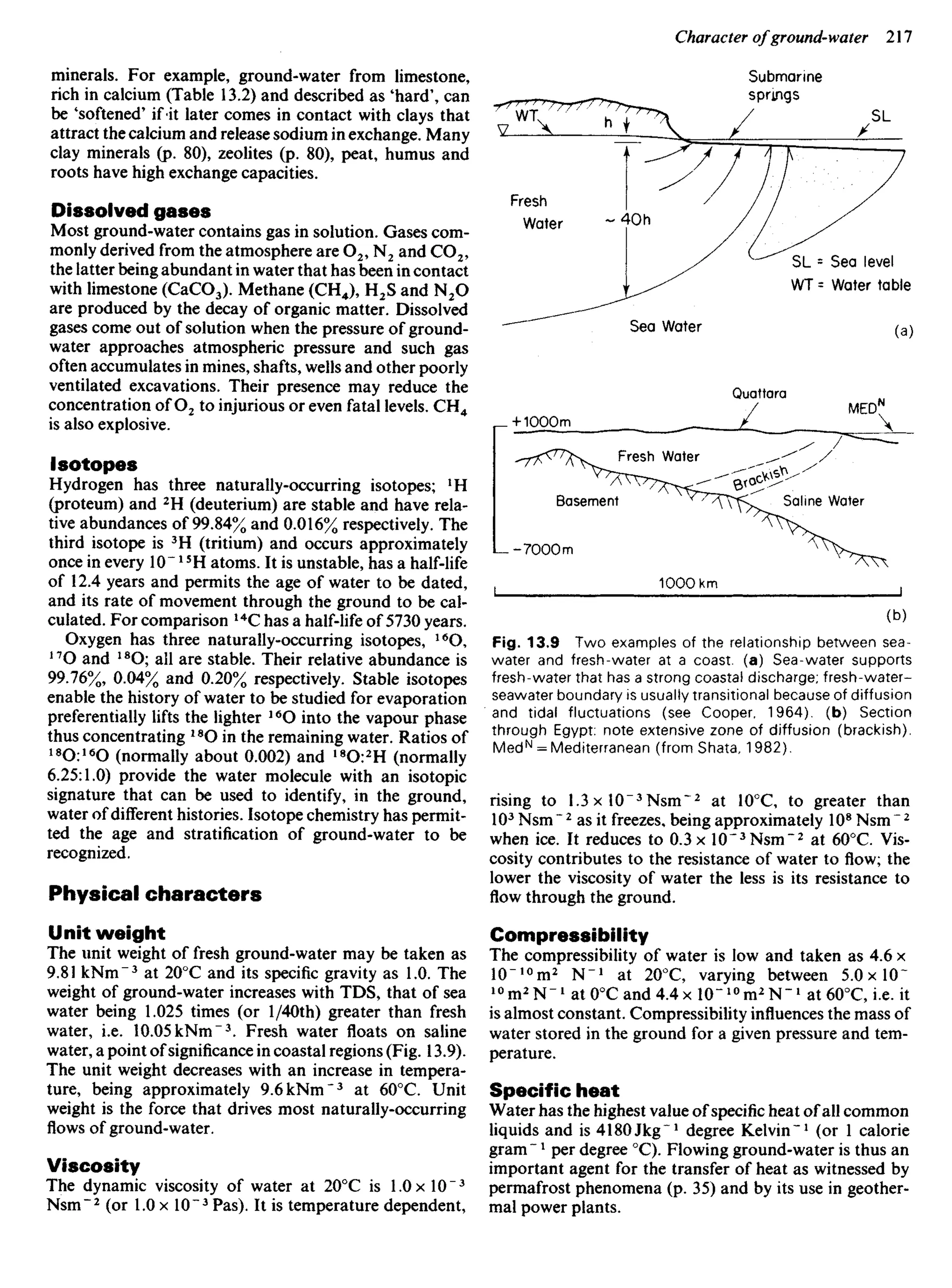
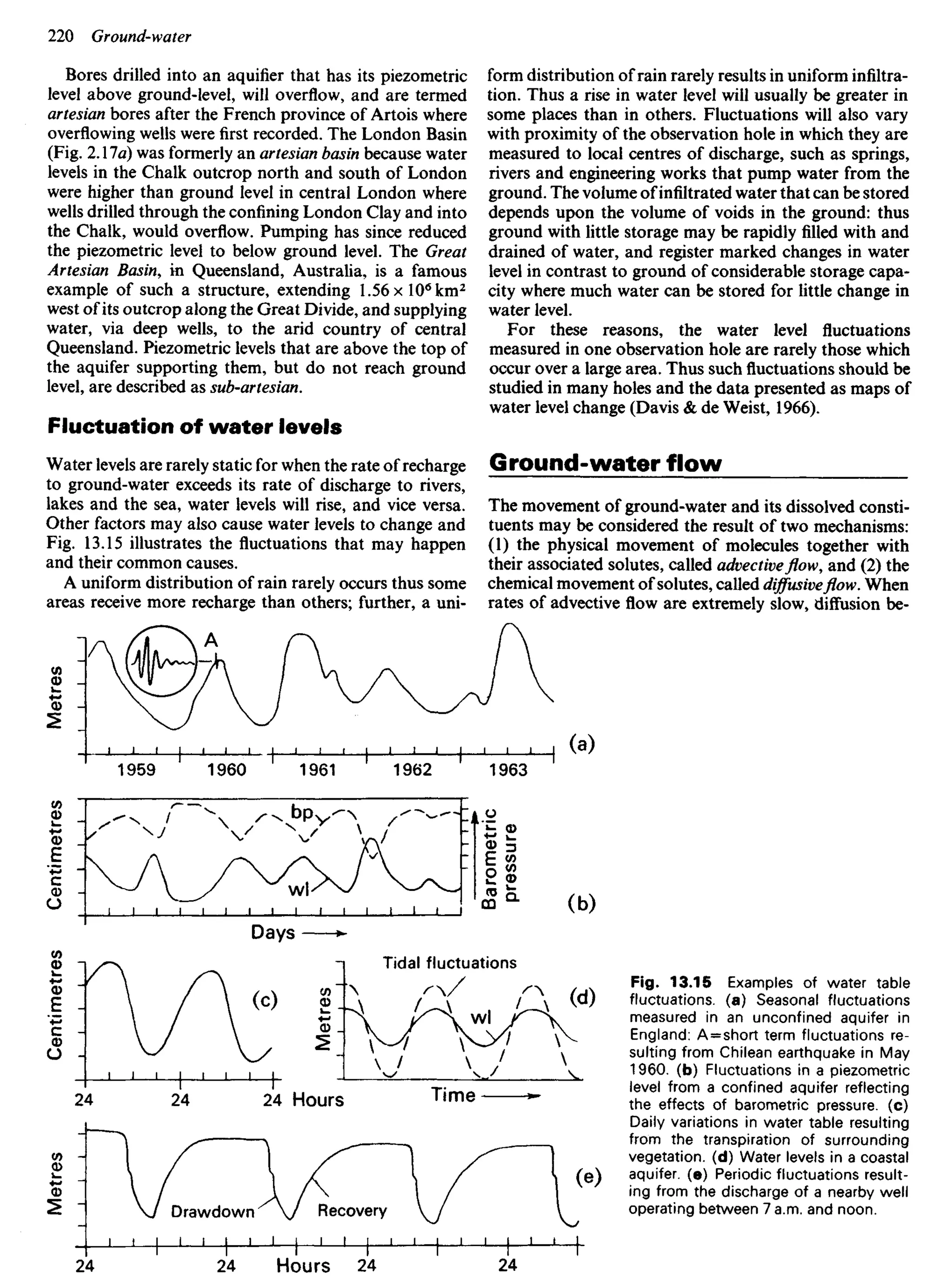
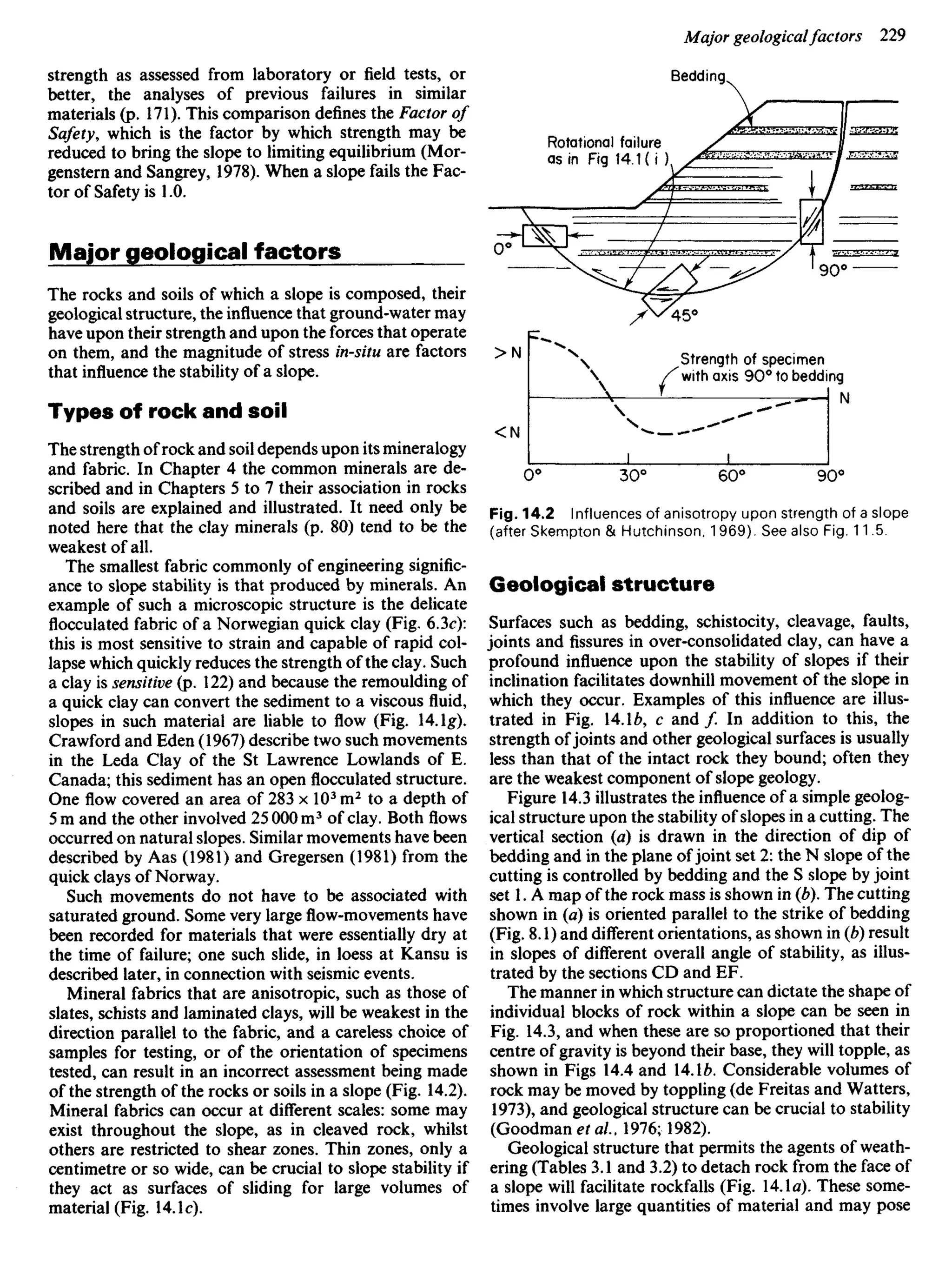
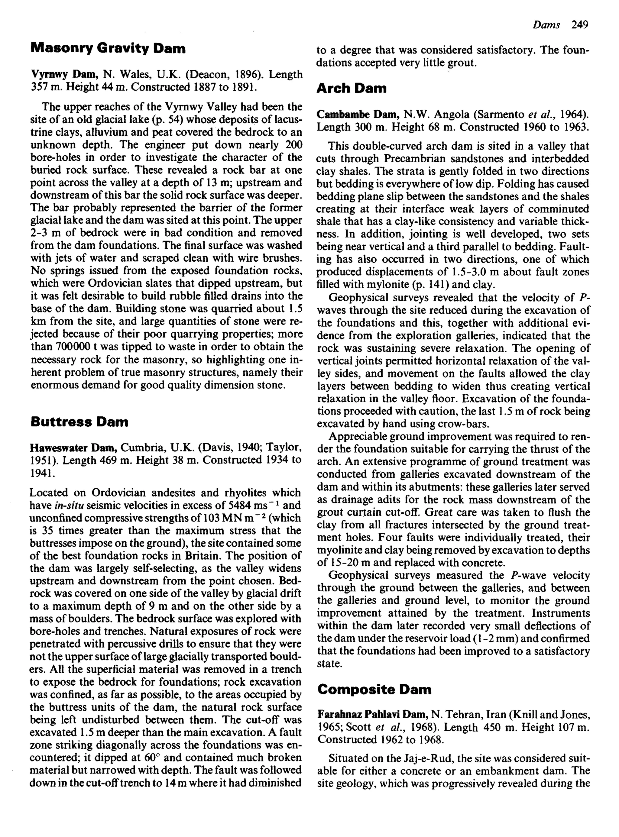
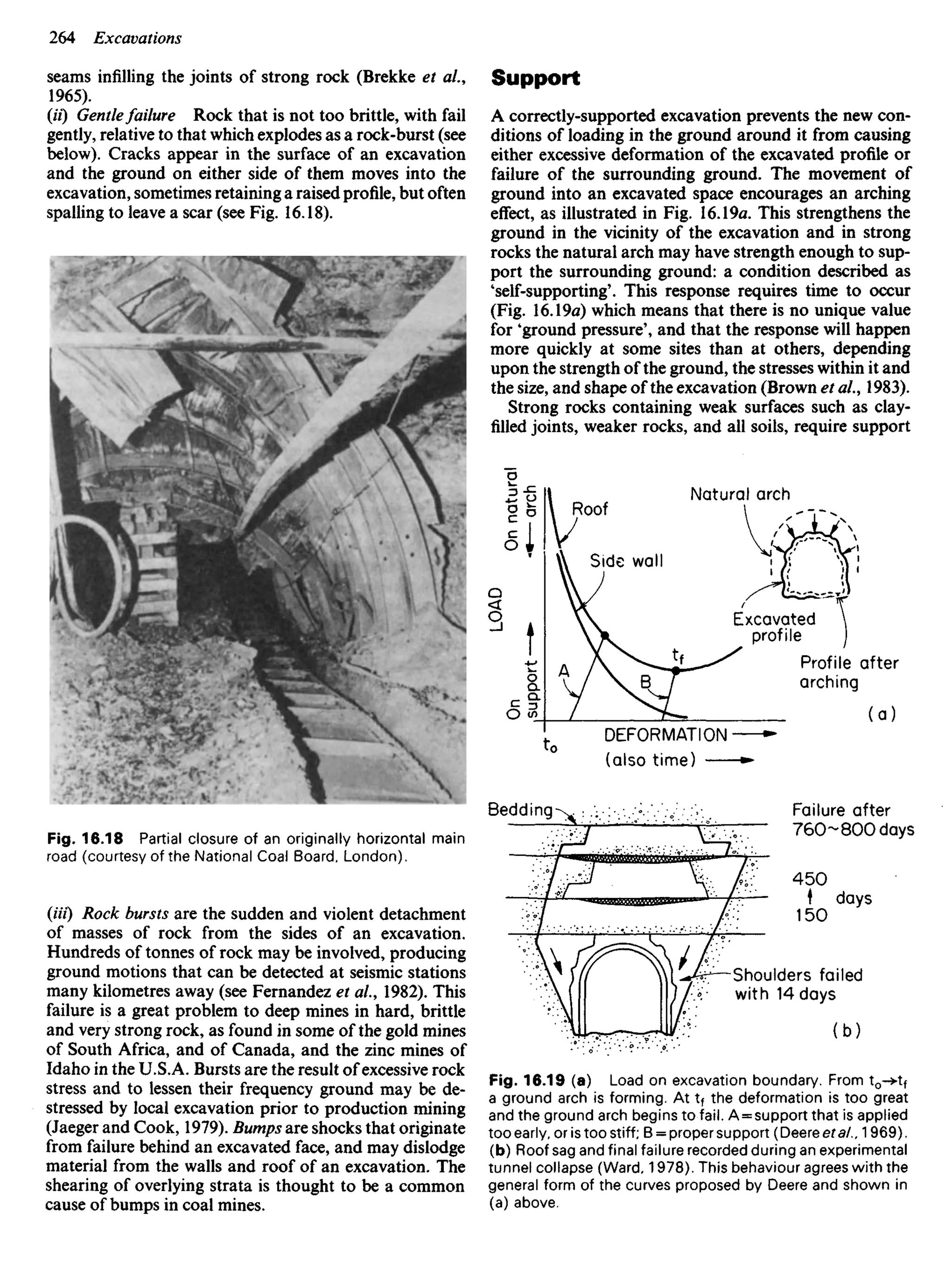
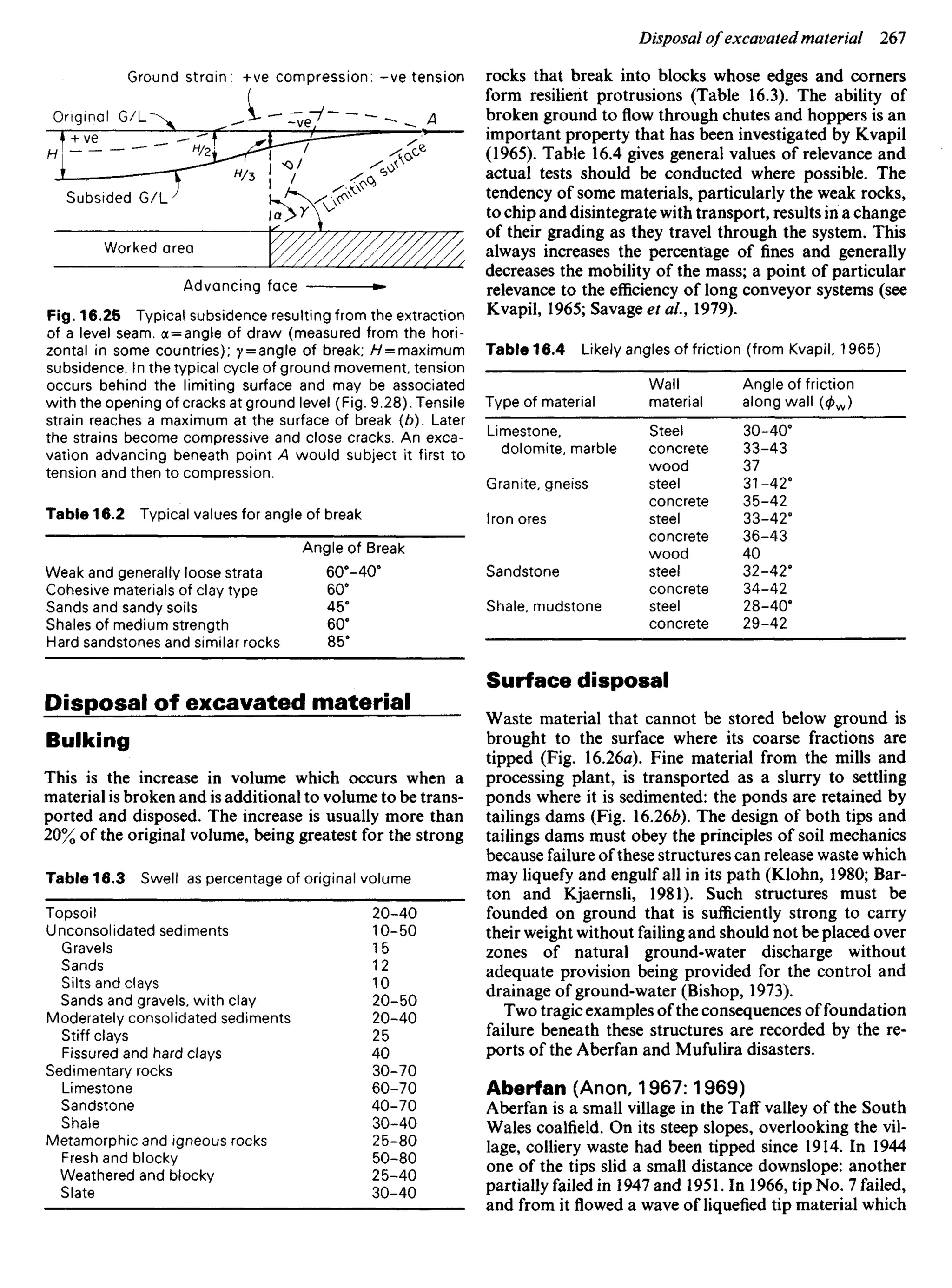
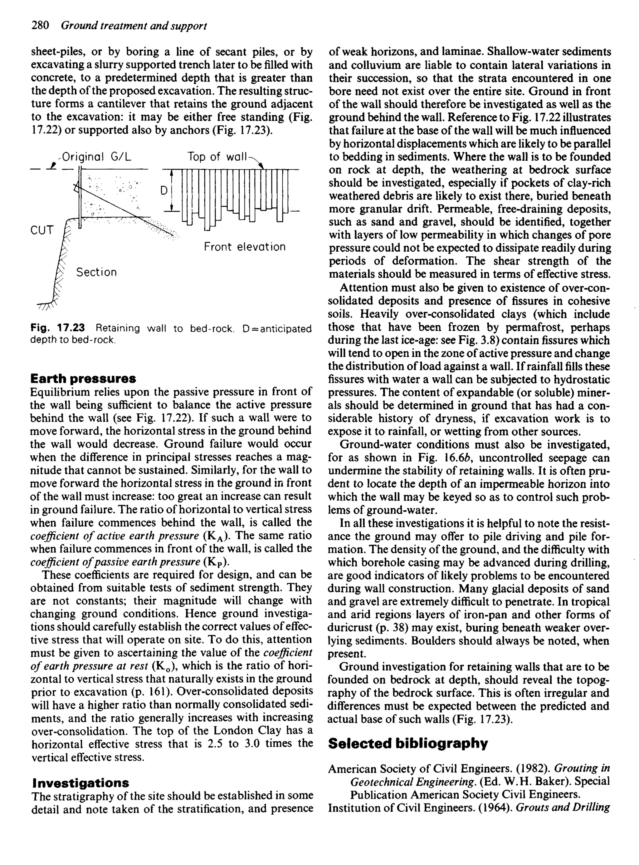
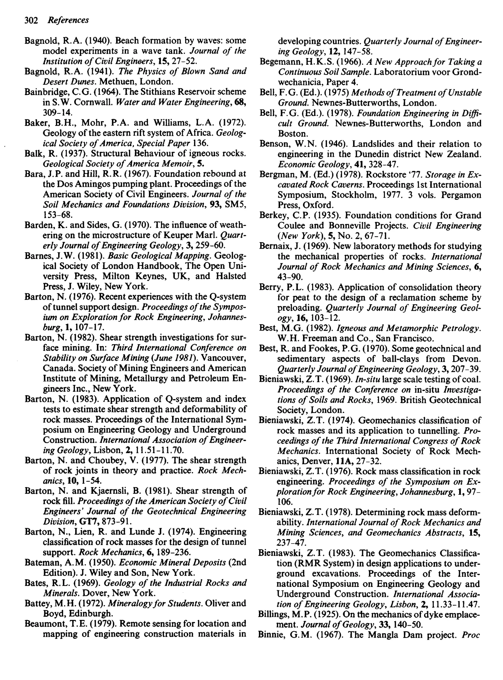
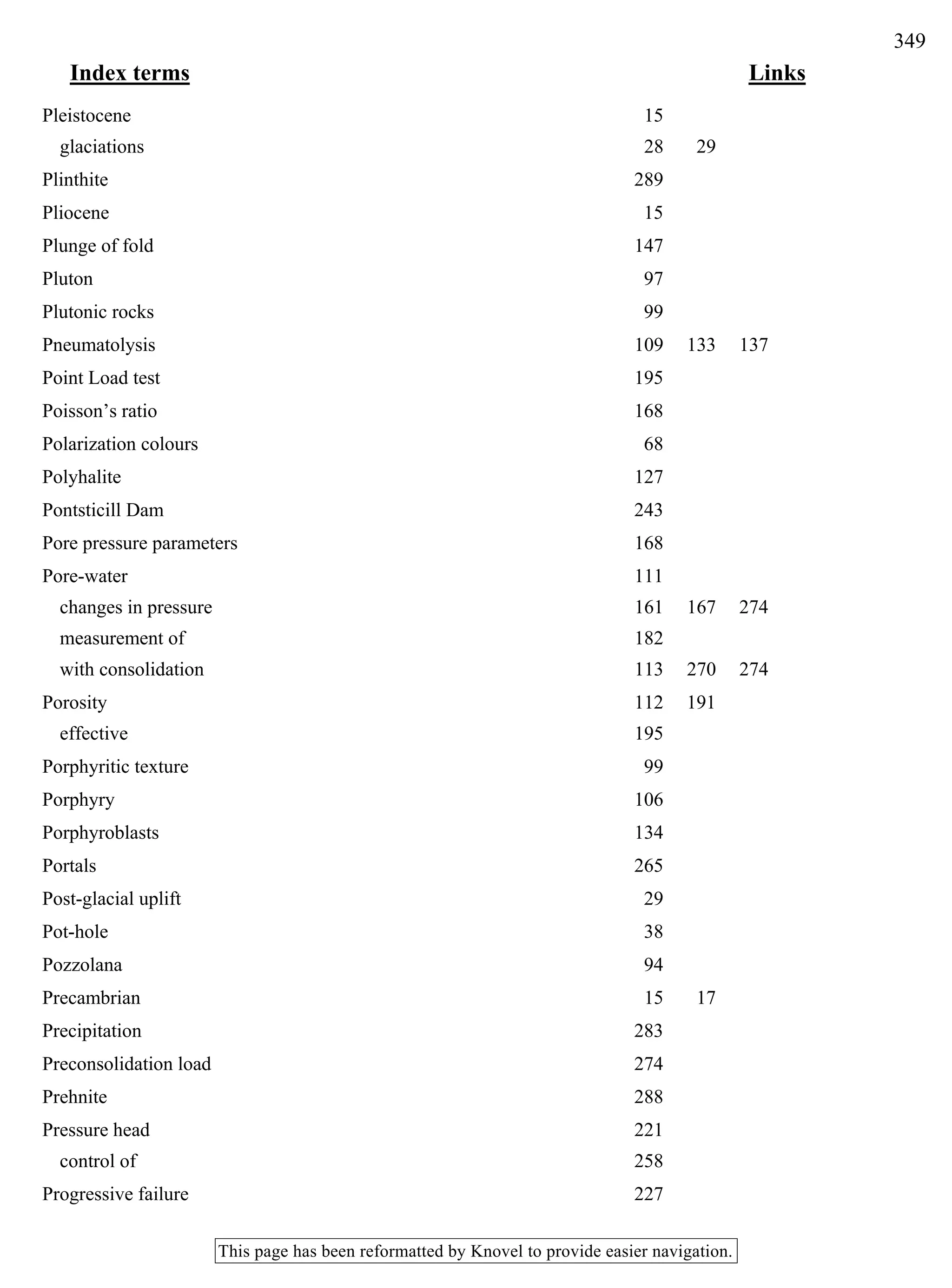
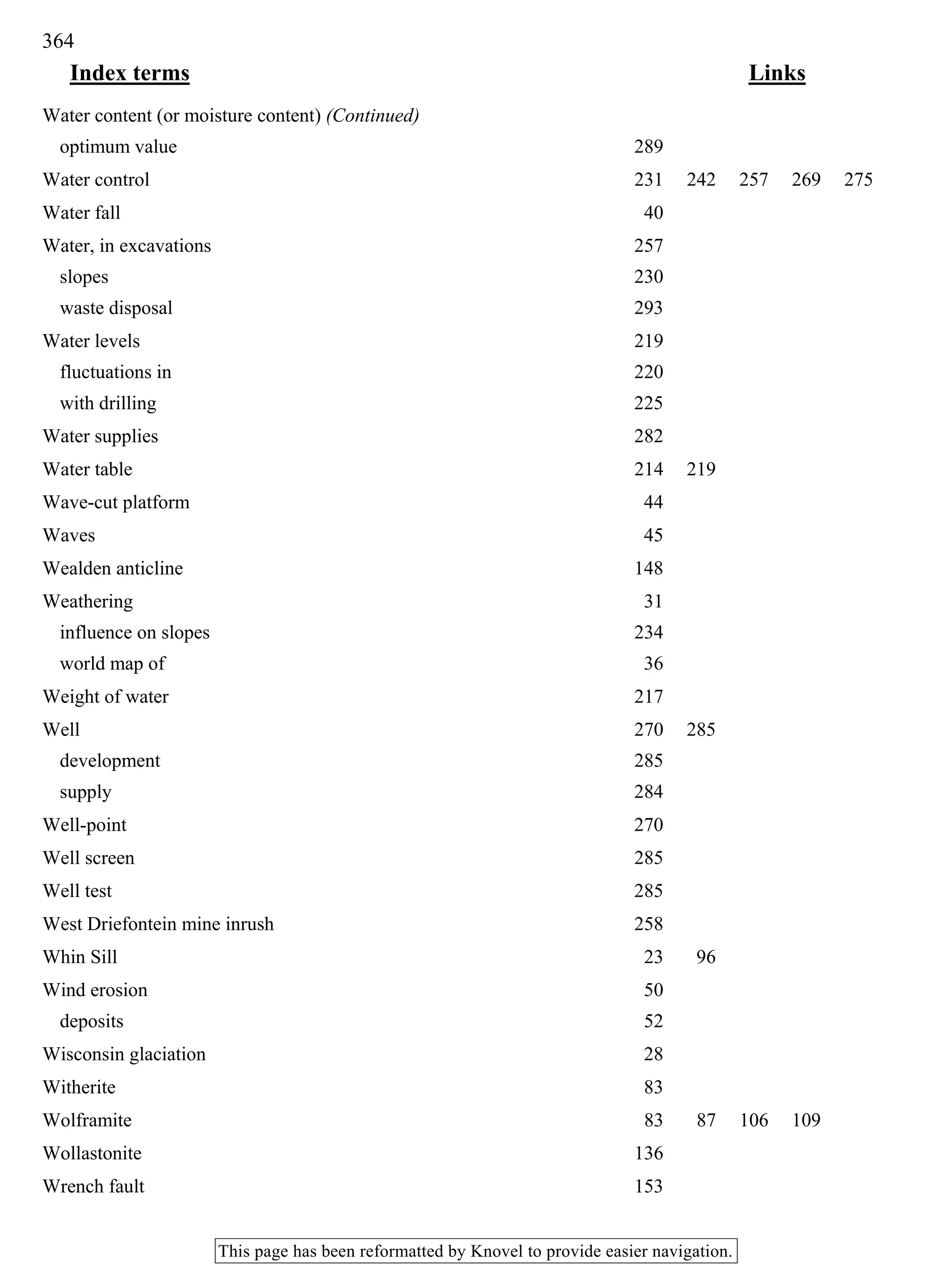
![may result from engineering work can be predicted by the
expression:
Au = B[Ao3 + A(Aa1-Aa3)]
Parameter A may be less than one, or negative, if the
deviator stress causing deformation and failure produces
a volumetric expansion of pore space sufficient to cause
pore pressure to decrease (cf. Figs 9.13, 9.15). When this
occurs effective stress on the surrounding particles and
hence the strength at their points of contact, will increase.
This increase in strength remains until more water can
migrate into the areas of reduced pore pressure and the
speed with which this occurs depends upon the permea-
bility of the material. For this reason the strength of
consolidated sediments and rocks of low permeability
may vary with time.
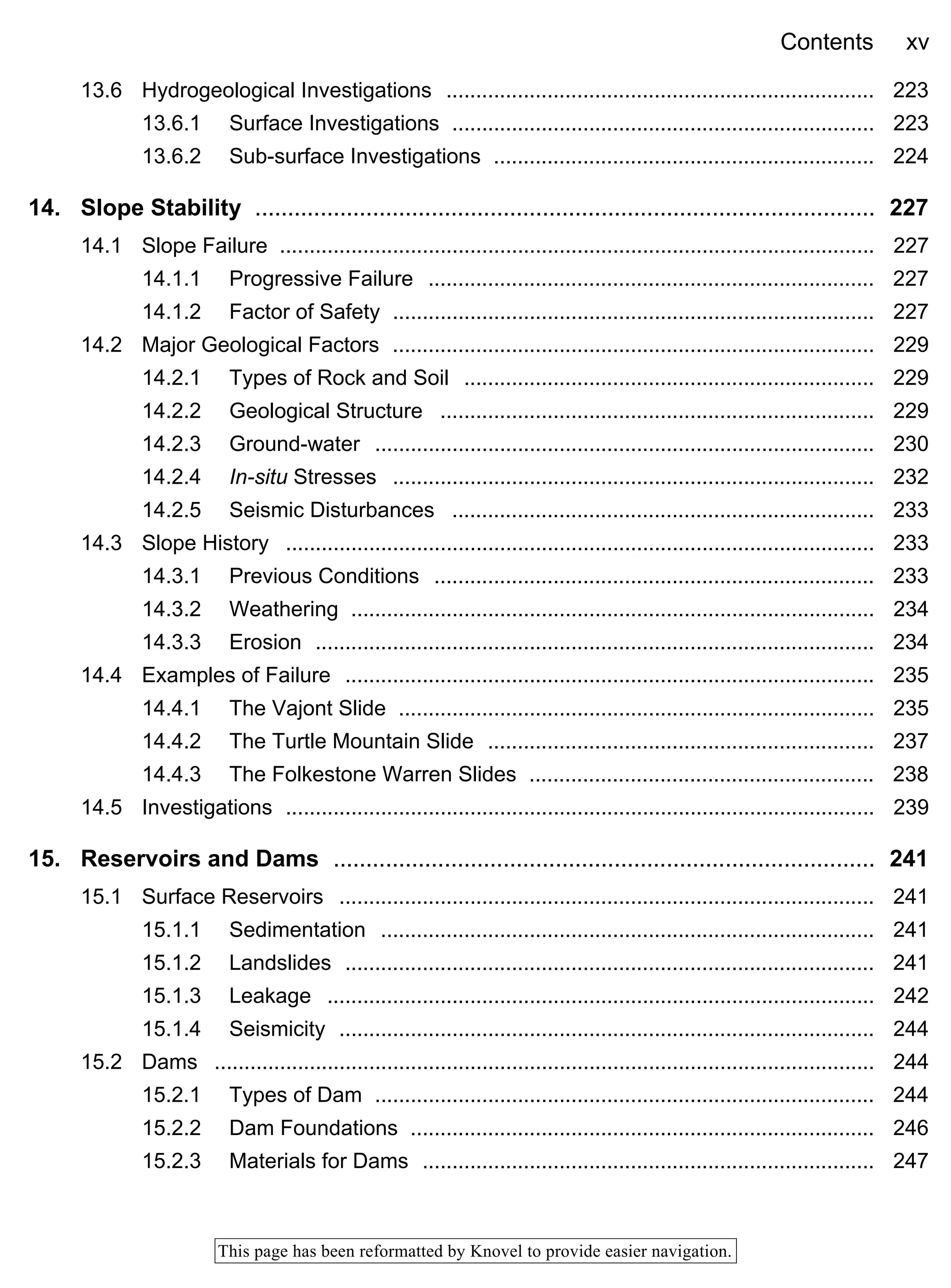
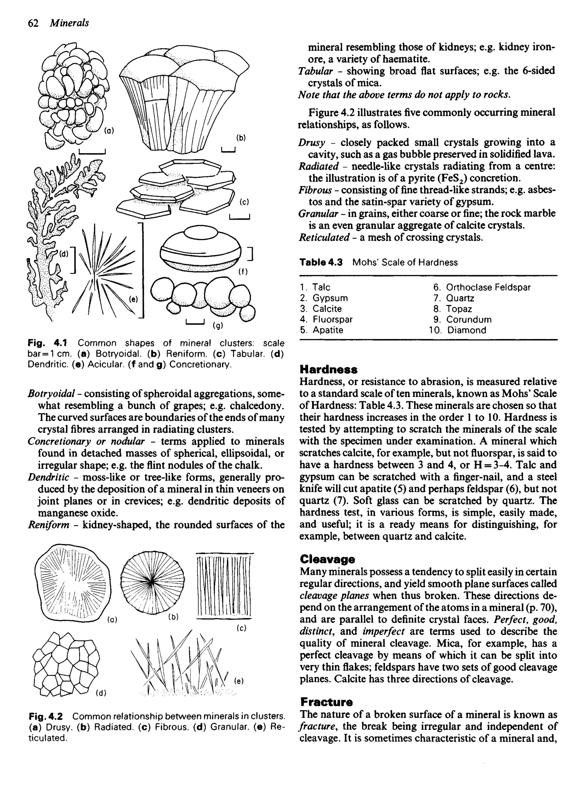
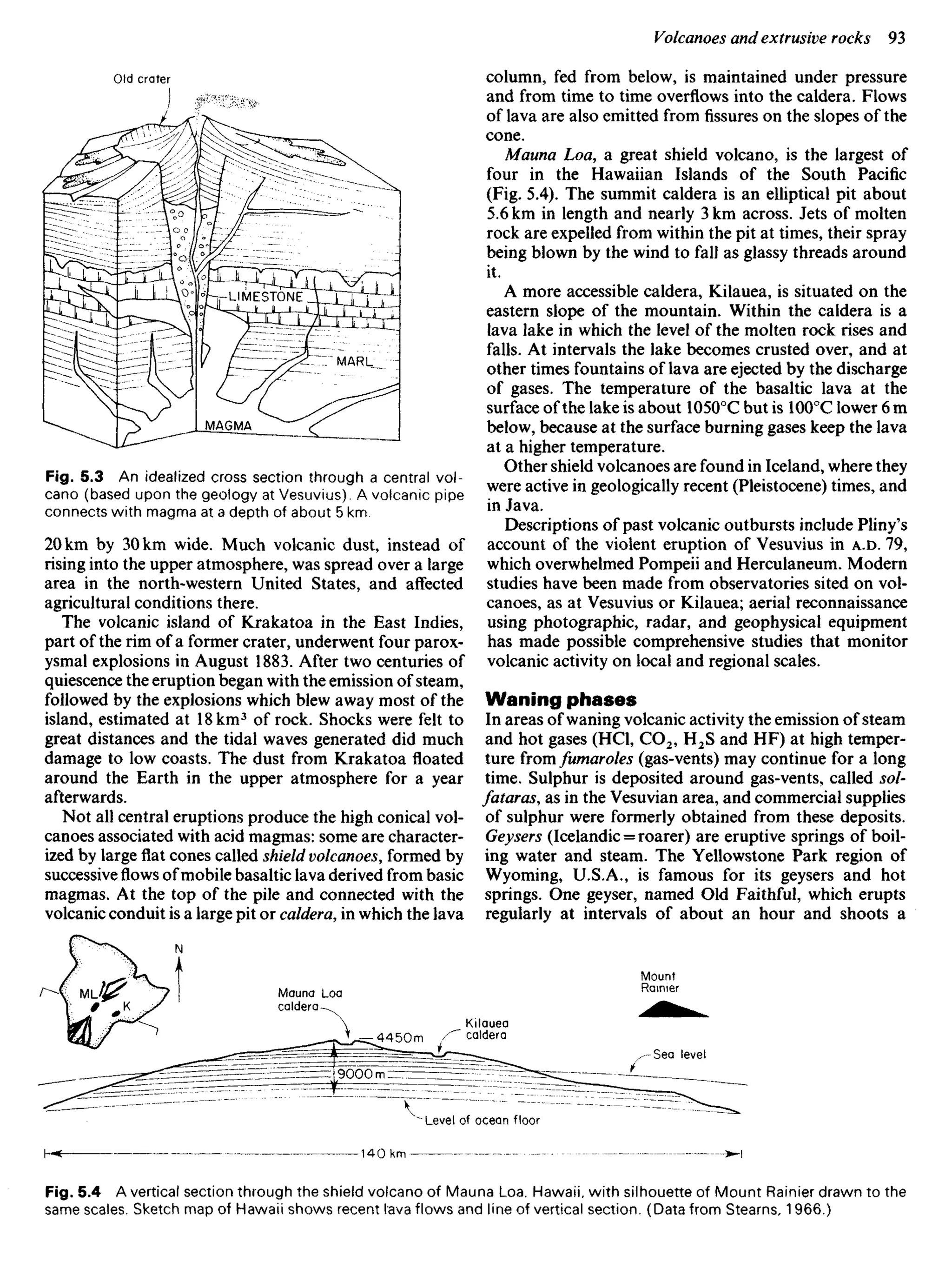
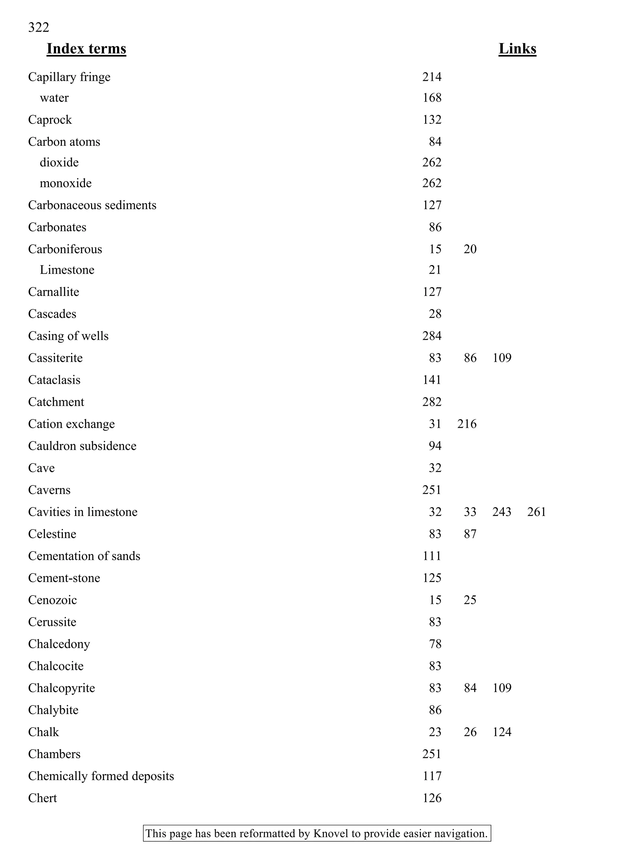
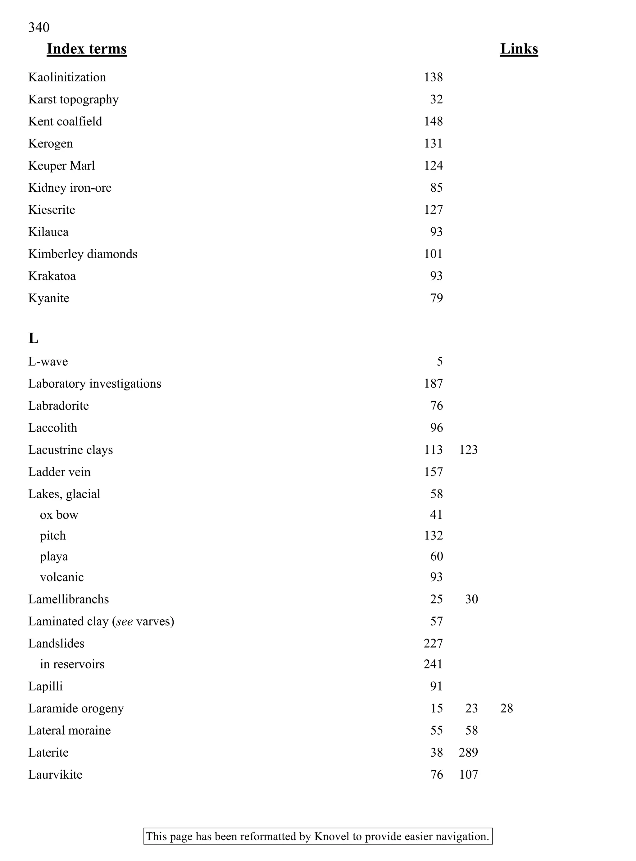
Table 9.3 Indicative values of pore-pressure parameter A
(Skempton, 1954 & 1961). Rocks may have negative values.
Soil Parameter A at failure
Loose sand 2.0 to 3.0
Soft clays Greater than 1.0
Normally consolidated clays 0.5 to 1.0
Over-consolidated clays 0.25 to 0.5
Heavily over-consolidated clays 0.5 and less
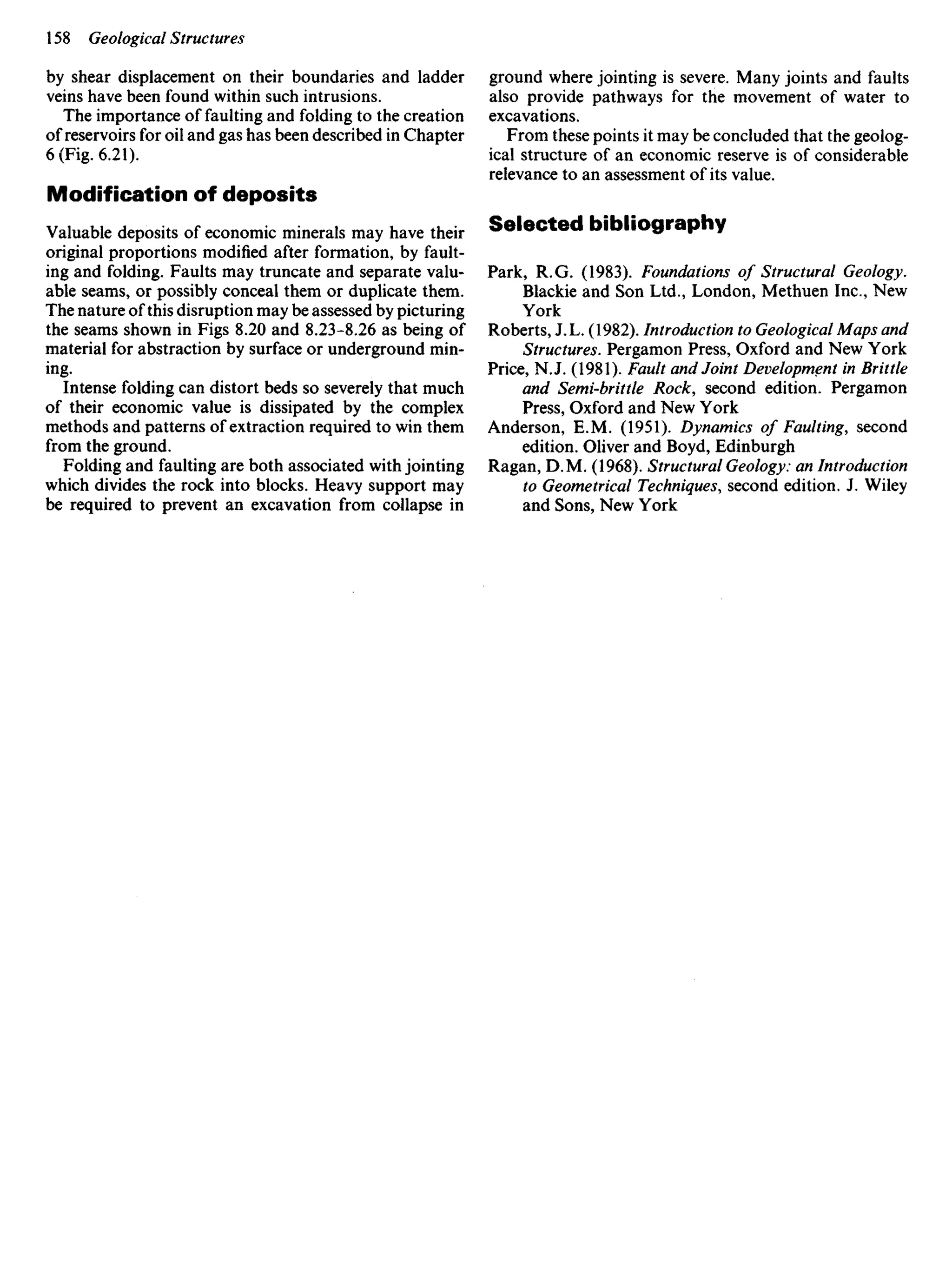
content at which the character of the soil is essentially
that a solid (as in a brick made from dry mud), or a plastic
(as in clay ready for moulding by a potter), or a liquid (as
in a slurry) is provided by index tests (p. 195) which define
the consistency limits: the limits are illustrated in
Fig. 9.22a. In these tests the samples are totally re-
moulded to prevent soil fabric from contributing to their
behaviour. The limits therefore reflect the mineralogy of
the soil (Fig. 9.22Z>).
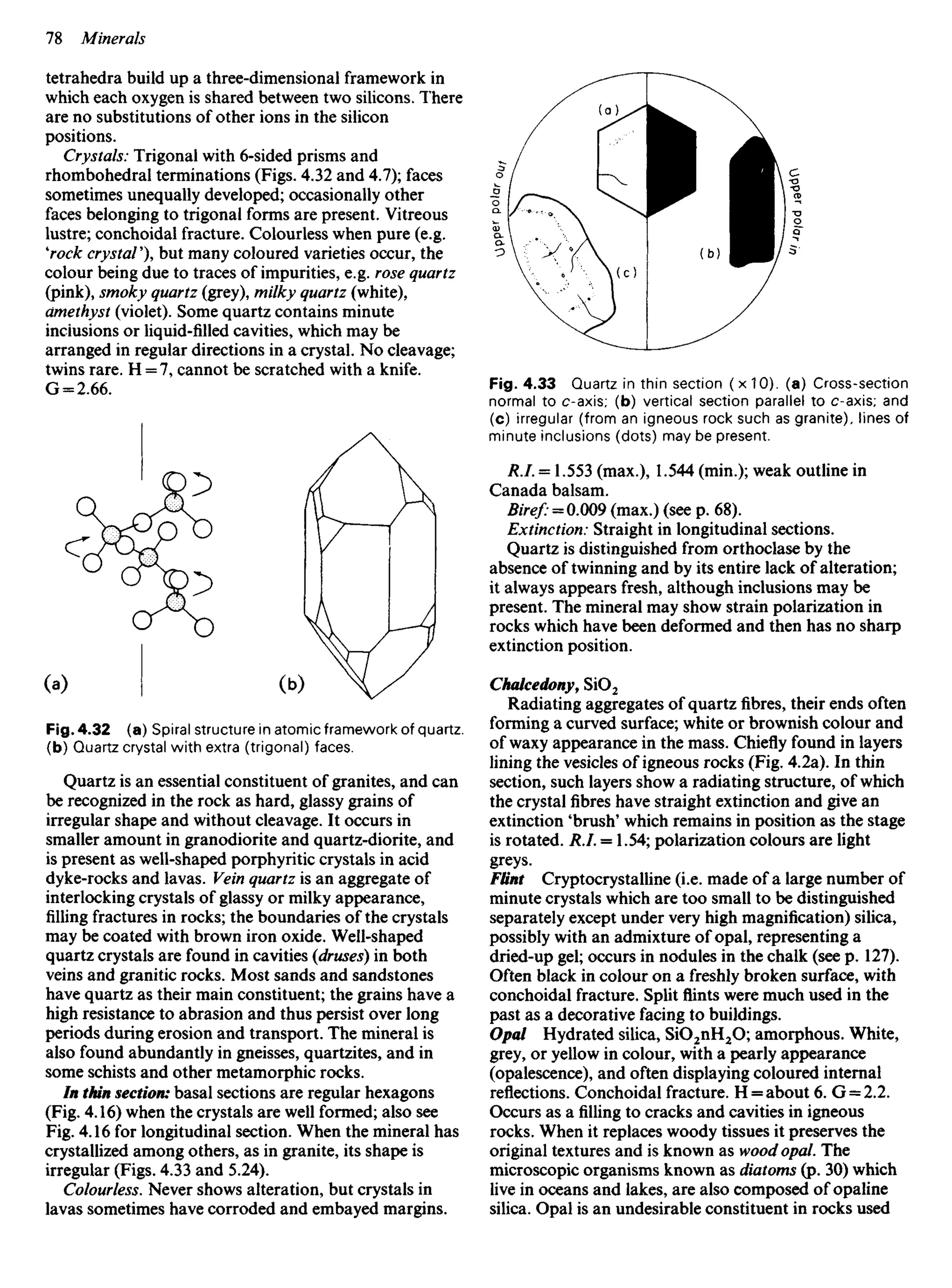
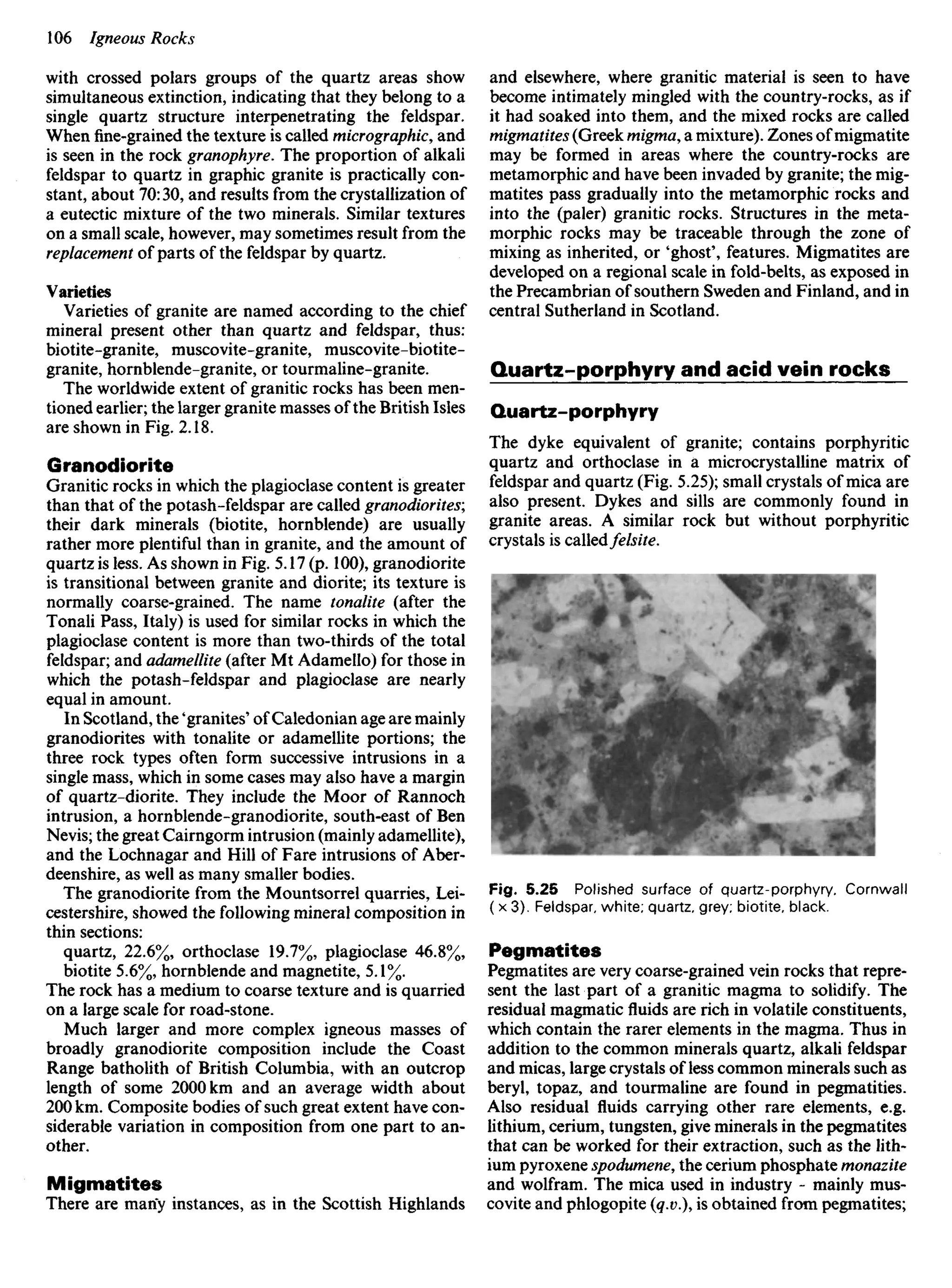
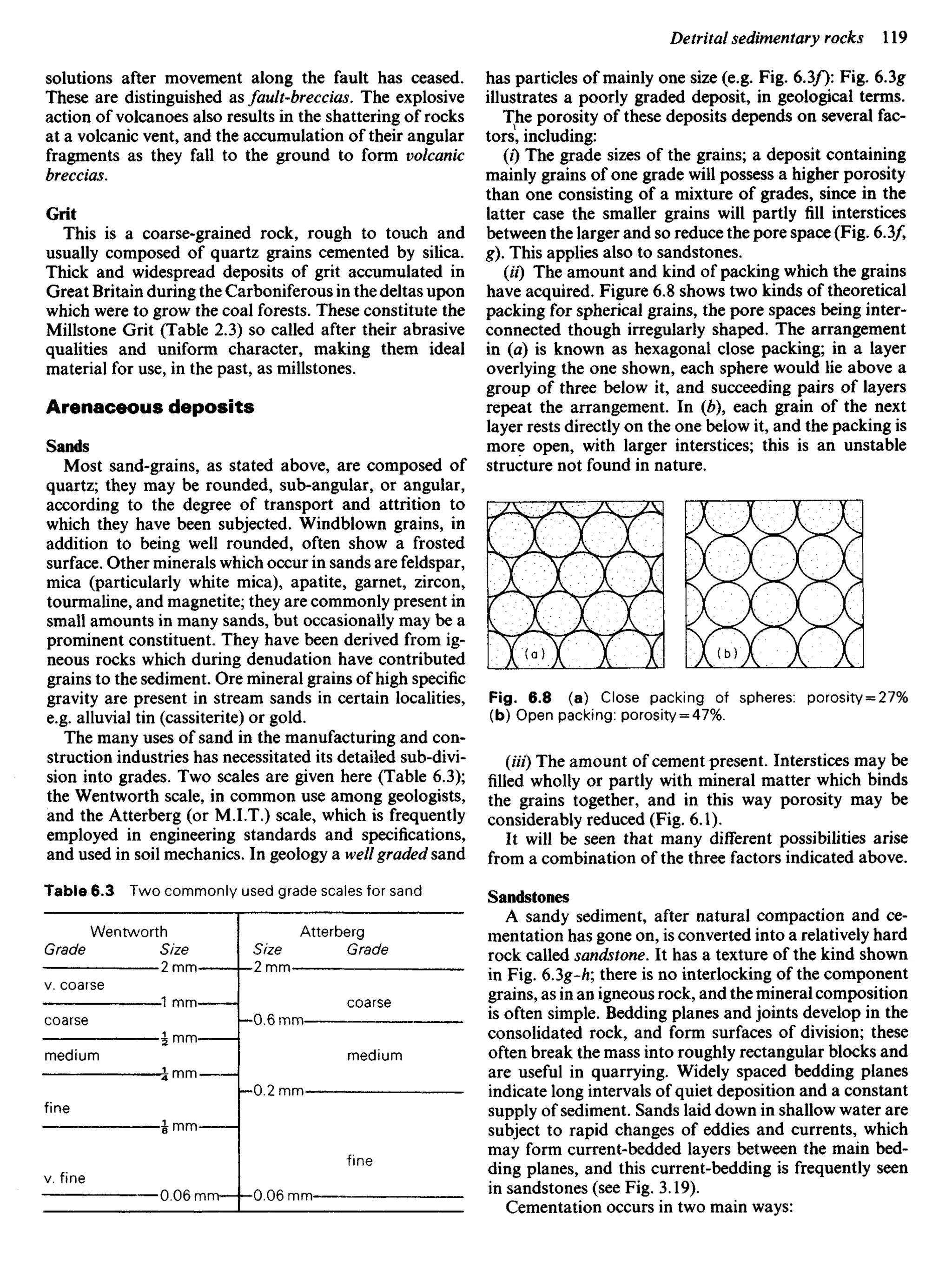
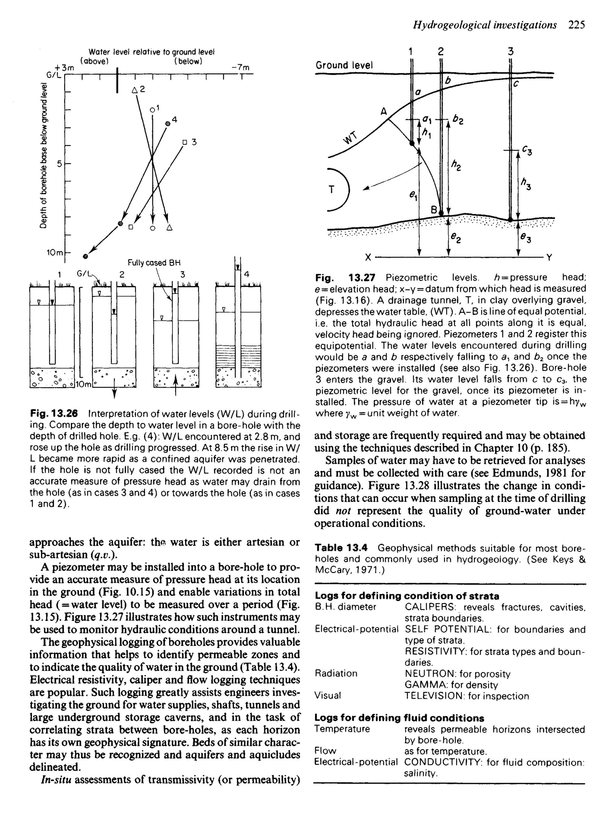
Weak soils, such as loose sand, that are partially satu-
rated may gain strength from the capillary tension of the
water meniscus around their areas of grain contact
(Fig. 9.23). This increases the effective stress upon the
grains and thus the frictional resistance at their points of
contact.
Mineral grain
Pore space
filled with air
at atmospheric
pressure Capillary
meniscus
Mineral grain
Consistency limits
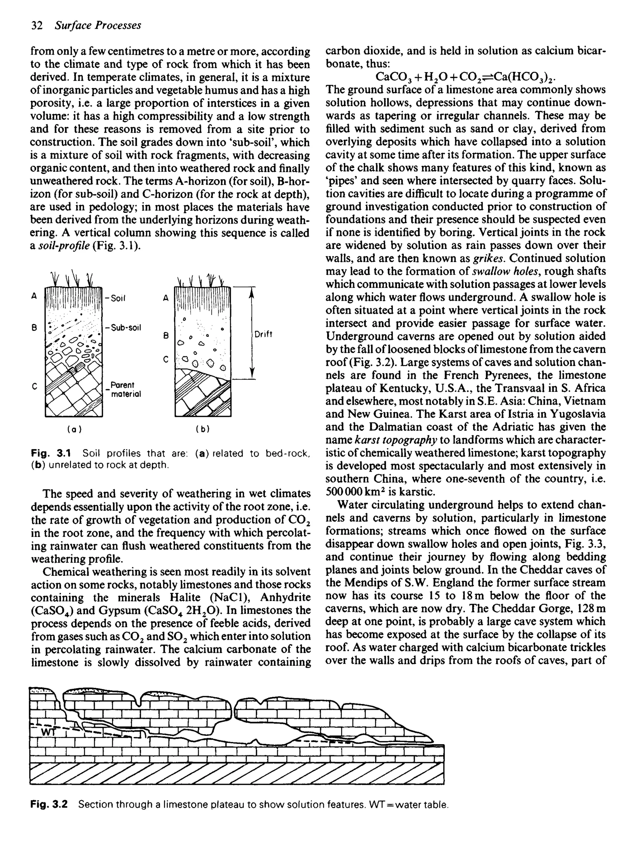
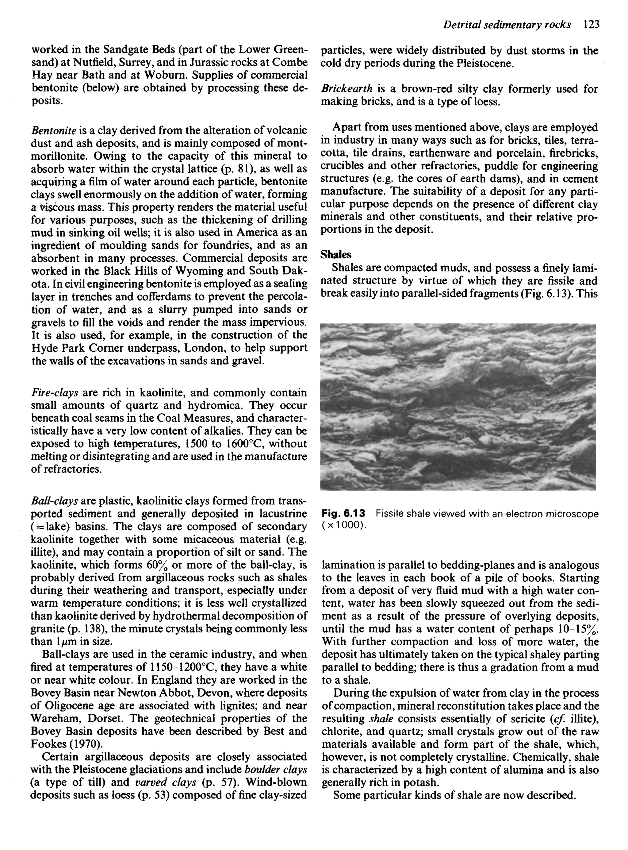
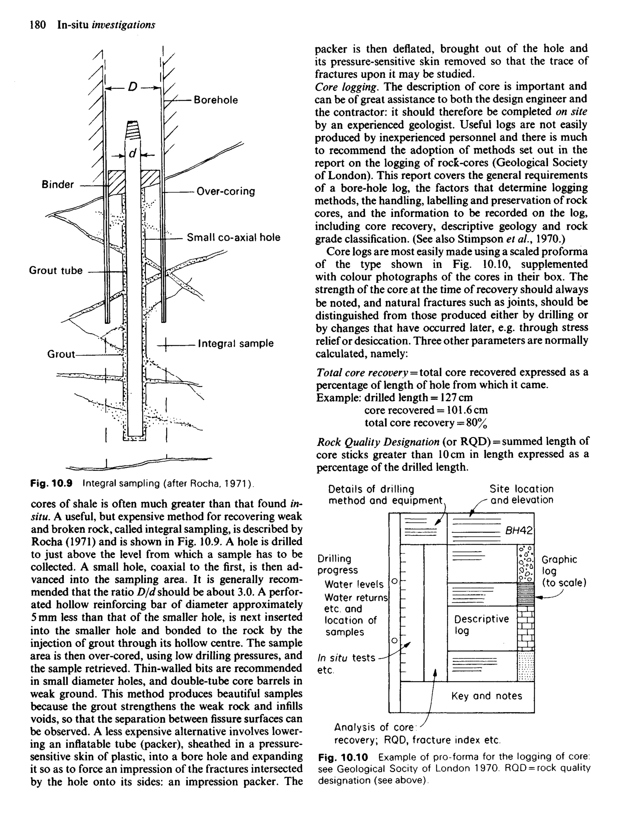
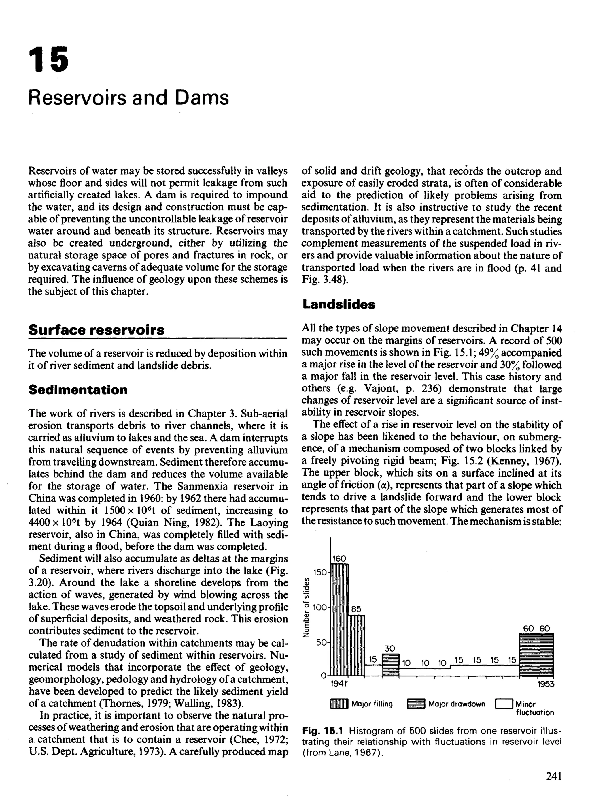
The volume and strength of most soils varies with their
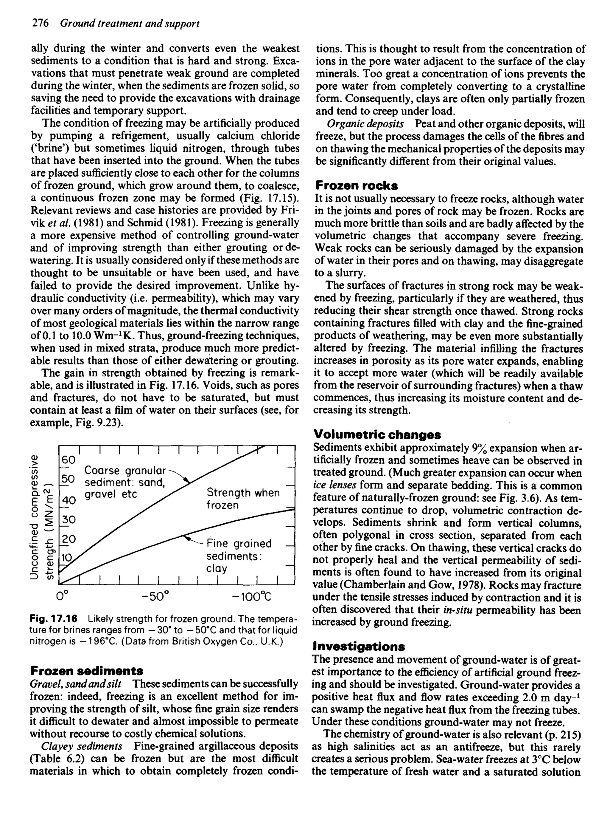
water content and the limit of this variation, i.e. the water Fig. 9.23 Capillary tension in pore spaces between mineral
grains. Large arrows indicate the attraction between grains
created by the meniscus.
Elastic moduli
Values of Young's Modulus and Poisson's ratio may be
obtained for rock and soil with comparative ease, but the
significance of the values obtained must be considered
with care as they may vary with time from those applic-
able to undrained conditions to those for drained condi-
tions. This is especially important for soils, where these
moduli should be determined experimentally using con-
ditions that simulate the range of stresses and type of
deformation that are expected to operate in the ground
during the engineering works.
Behaviour of surfaces
Over-consolidated sediments and all rocks that have ex-
perienced unloading and uplift (p. 160) contain micro-
fractures and other failure surfaces such as joints and
fissures: many bedding planes will have separated, some
containing a visible parting. Such surfaces have a strength
that is less than that of the rock or soil in which they
occur and they are a major source of weakness: they have
formed by failure either in tension or in shear.
Tensile fractures such as joints, tend to be discontin-
Volume
No further decrease
in volume with
drying LIQUID
PLASTIC
Plasticity
index
Water
content
Water
content
(%)
Sandy
silts
Silt
Silty
clay
Clay
SOLID
Plasticity index
Fig. 9.22 (a) Consistency limits: SL — shrinkage limit.
P/. = plastic limit. Z./.= liquid limit, I/=total soil vol
ume = volume of pores (VP) + volume of solid grains (V$)
Water content= (Mass of water) 4- (mass of solid) and can be
more than 100%. (b) Influence of mineralogy upon consis-
tency limits.](https://image.slidesharecdn.com/ageologyforengineersseventhedition-240123054612-a0c16209/75/A_Geology_for_Engineers_Seventh_Edition-pdf-152-2048.jpg)

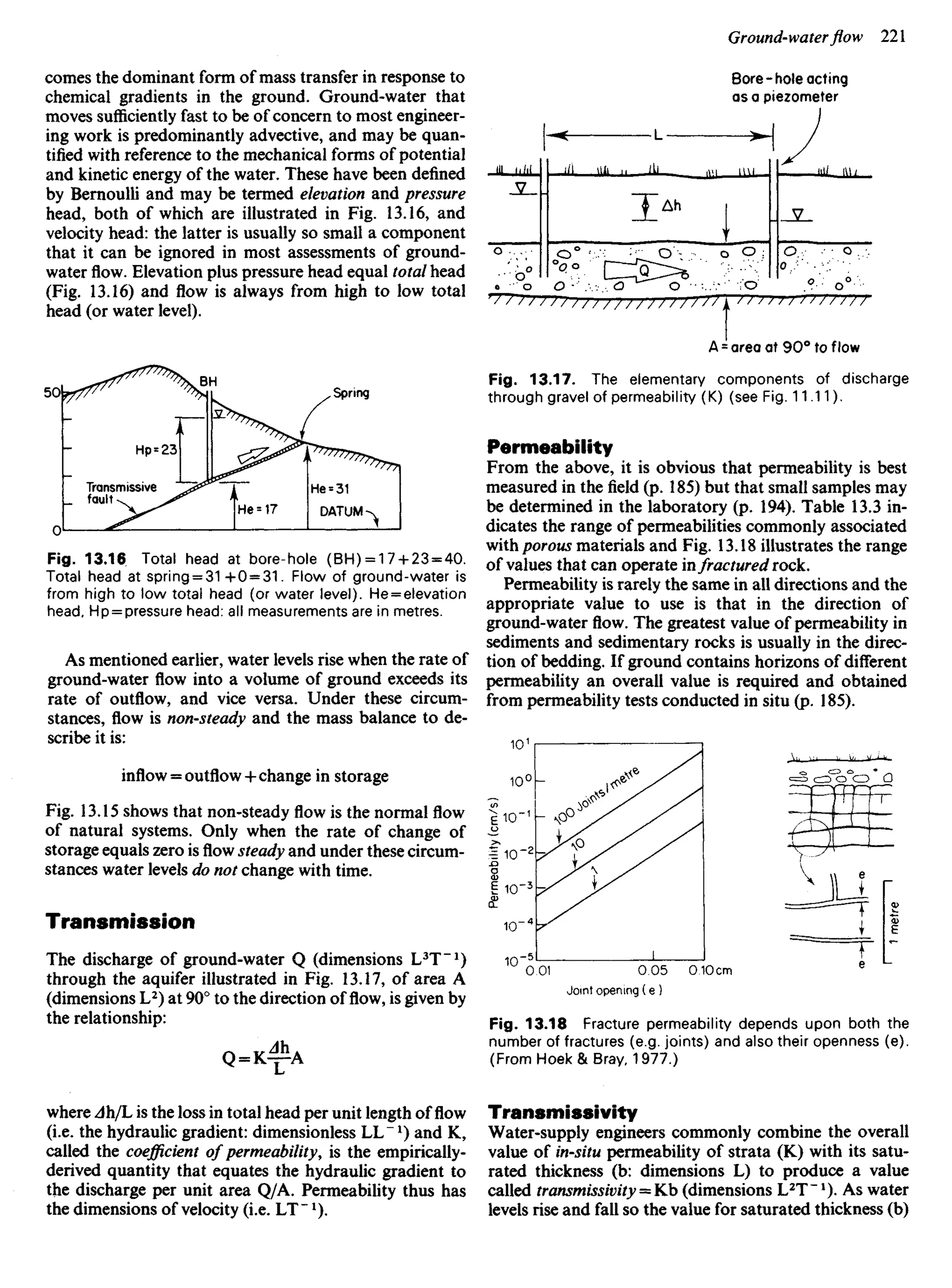
![performed upon it (see Brorns, 1980 and Amer. Soc.
Testing Materials, 1970). No sample can be collected
without it being disturbed in some way, for the reasons
explained in Chapter 9,
In practice two categories of sample may be obtained:
(0 Routine sample, i.e. one slightly disturbed but col-
lected with reasonable care by experienced staff who
should ensure that it suffers no avoidable change in mois-
ture content, does not lose any of its constituents (e.g.
fine sand from mixed gravel) and is not deformed by
careless handling if its strength or permeability are to be
measured. Routine samples must be correctly stored and
adequately labelled. Table 11.1 provides a guide to sam-
ple requirements.
(U) Research sample, i.e. one collected with the great-
est care possible, often using expensive procedures to
reduce disturbance: such a sample cannot be economic-
ally provided by commercial routine sampling.
The difficulties of obtaining routine samples using con-
ventional methods of commercial sampling are illustrated
by Kallstenius (1963) and Rowe (1972).
Guidelines
The following guidelines should be observed when pos-
sible and considered the minimum standard required for
routine sampling.
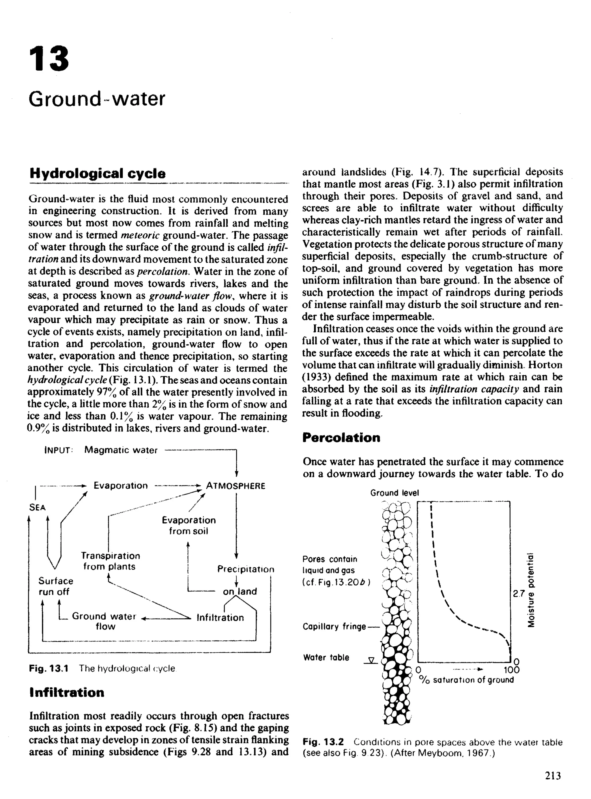
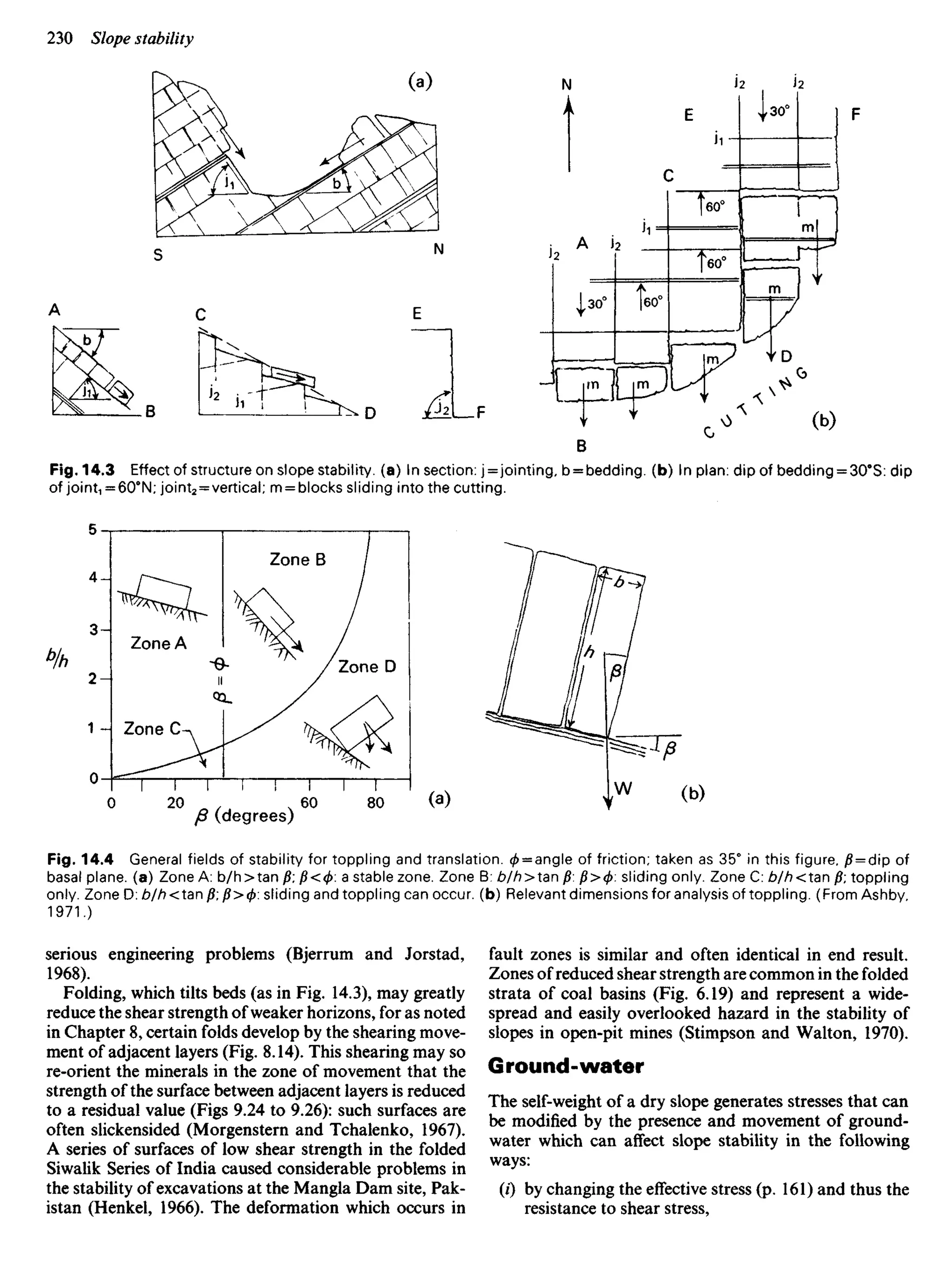
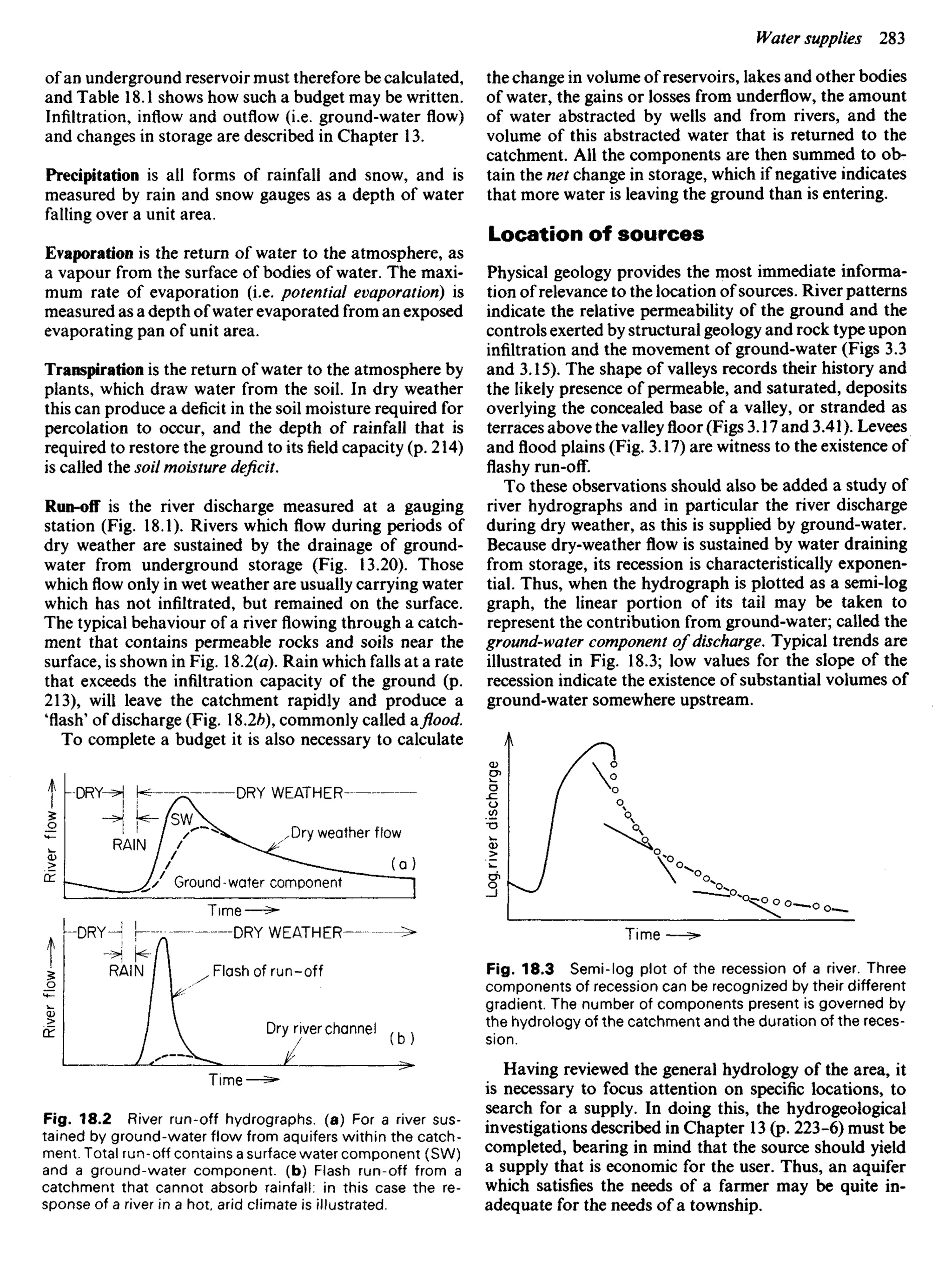
Selection of samples
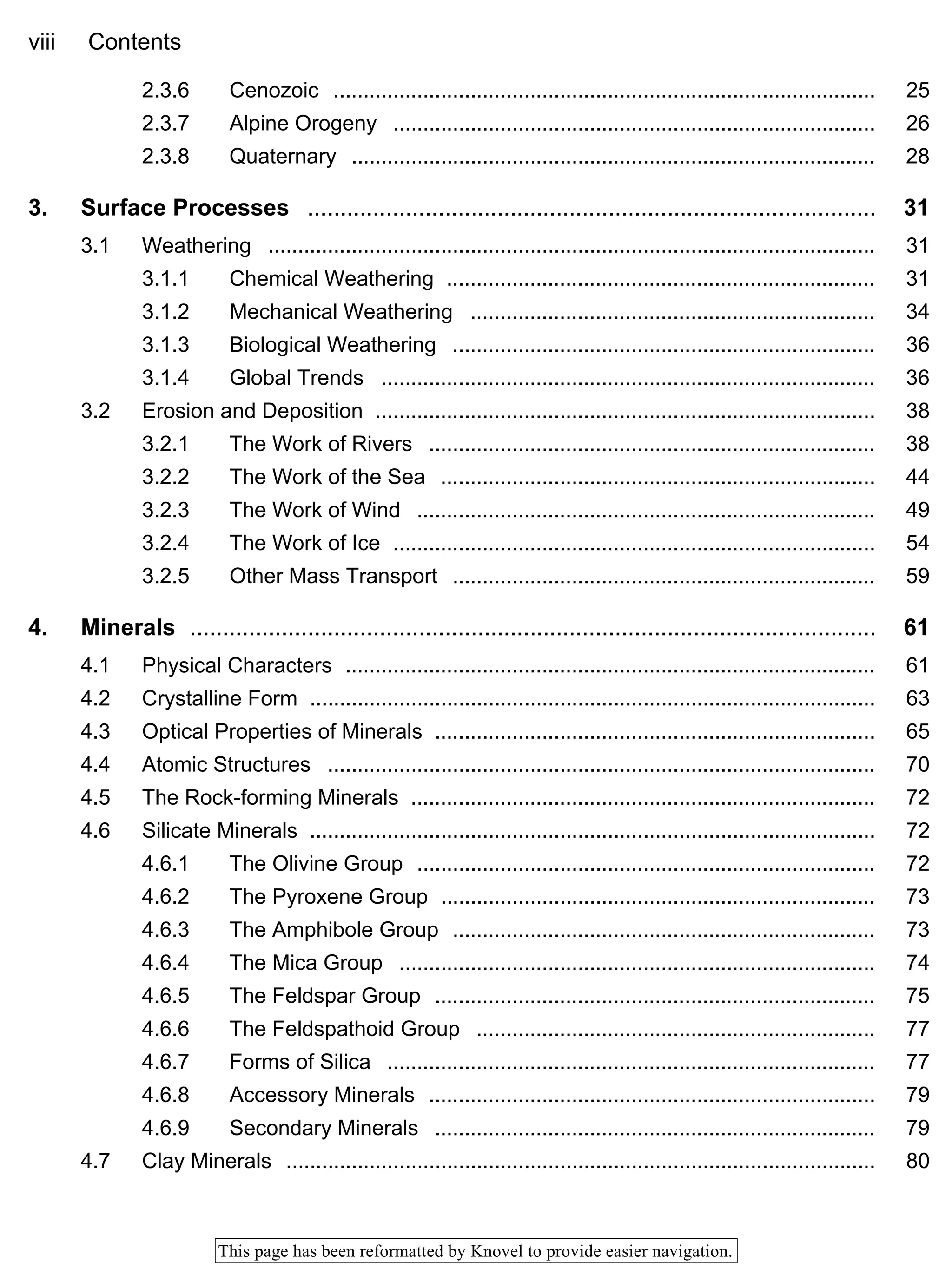
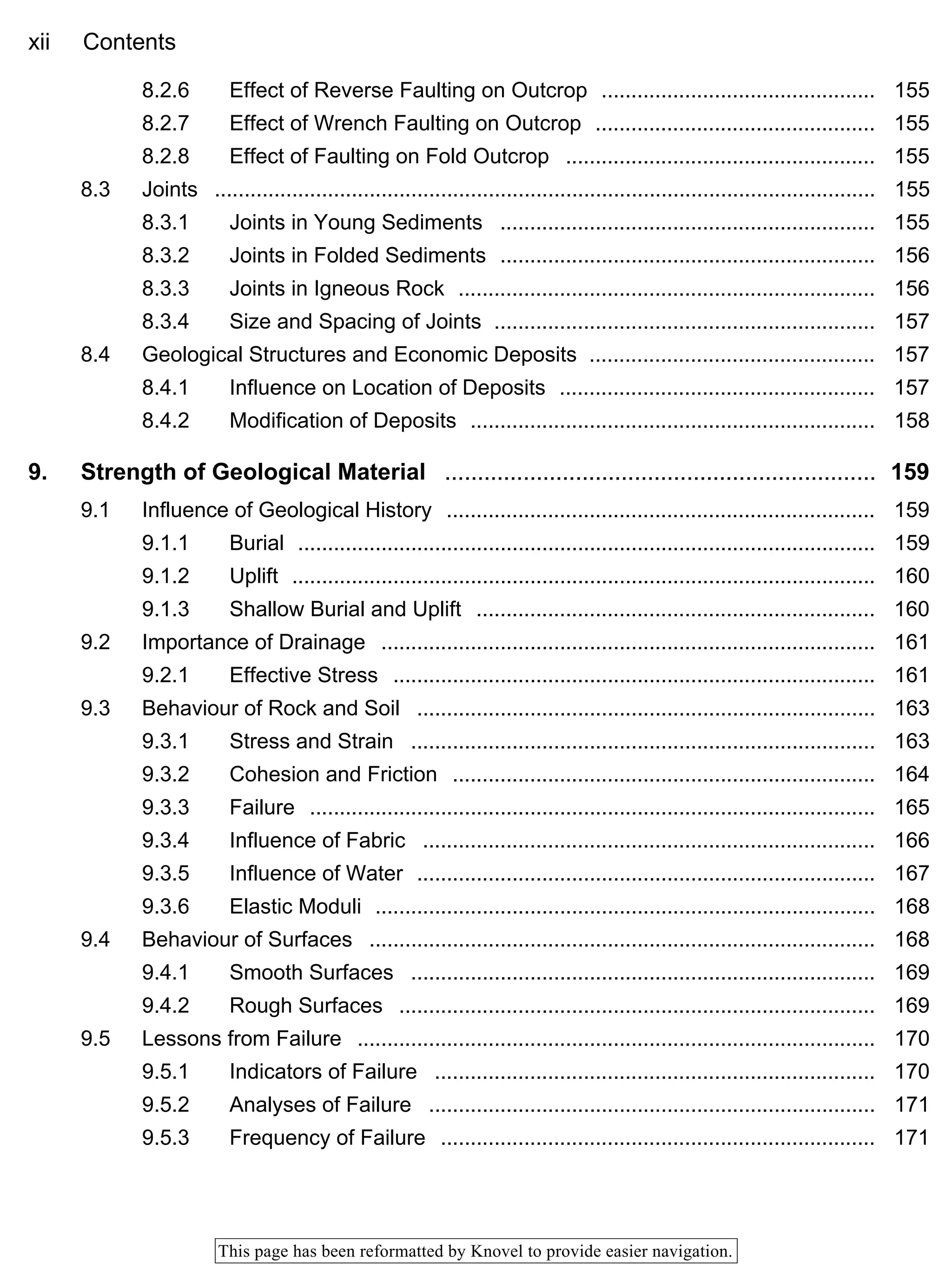
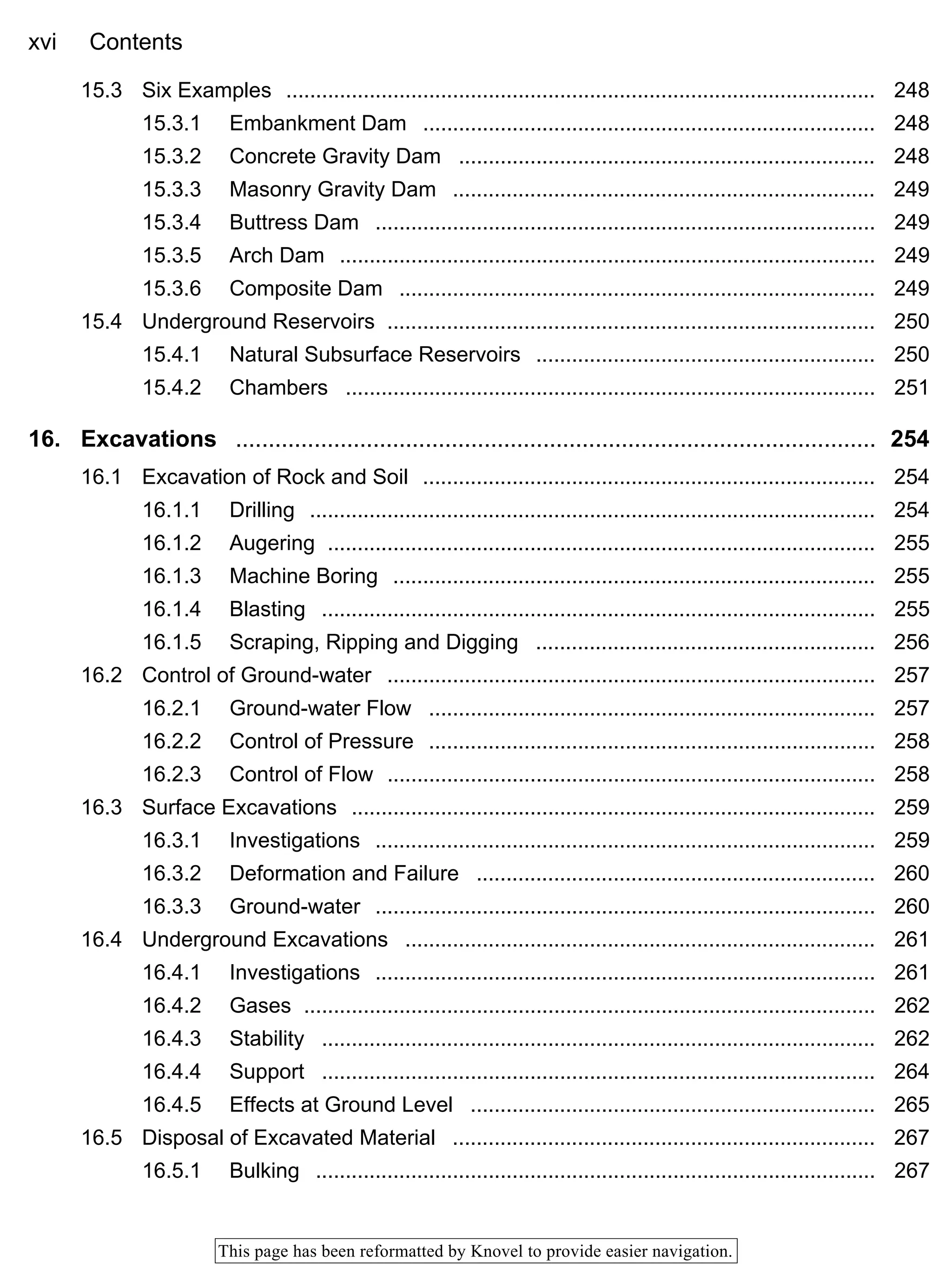
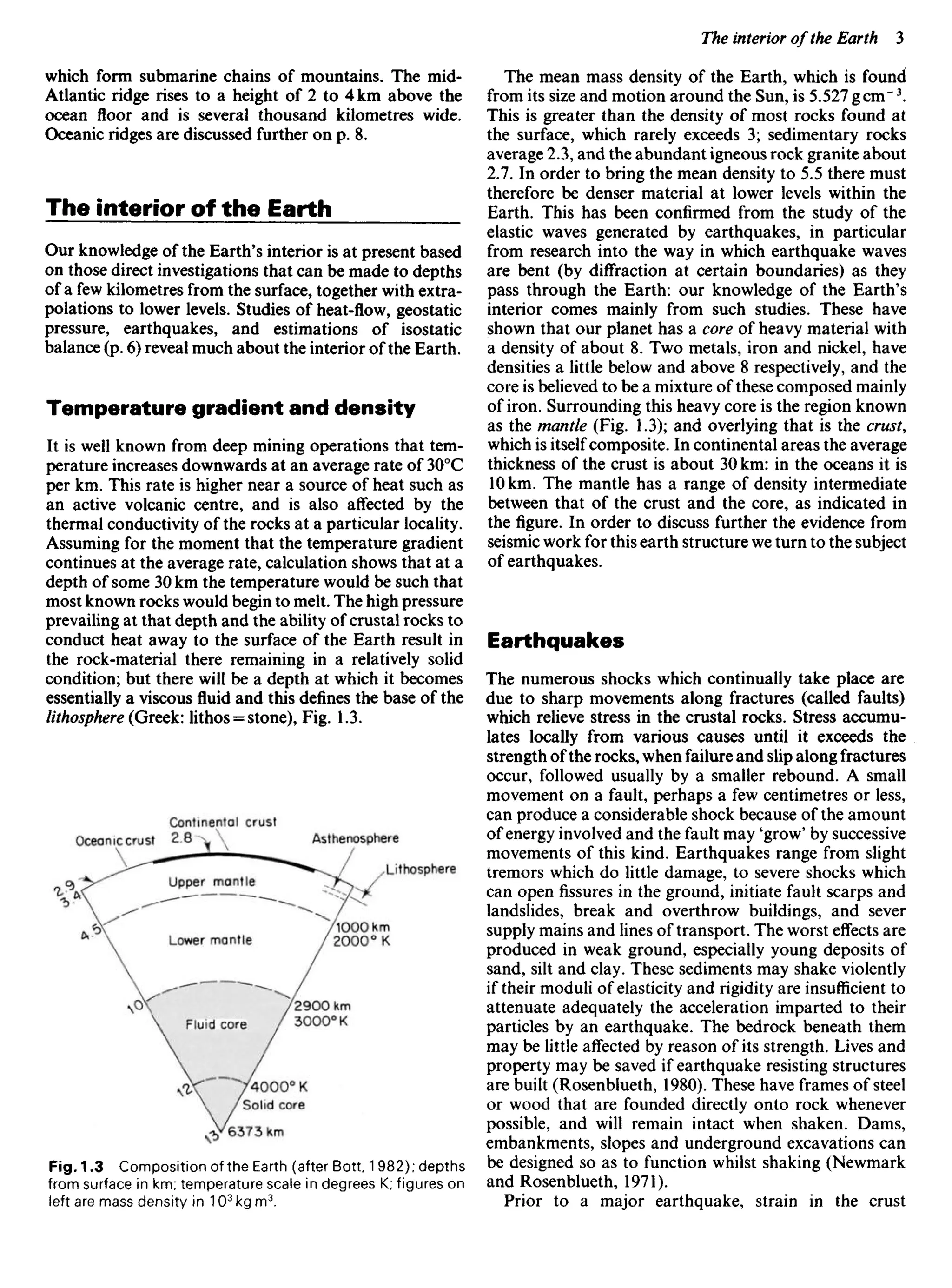
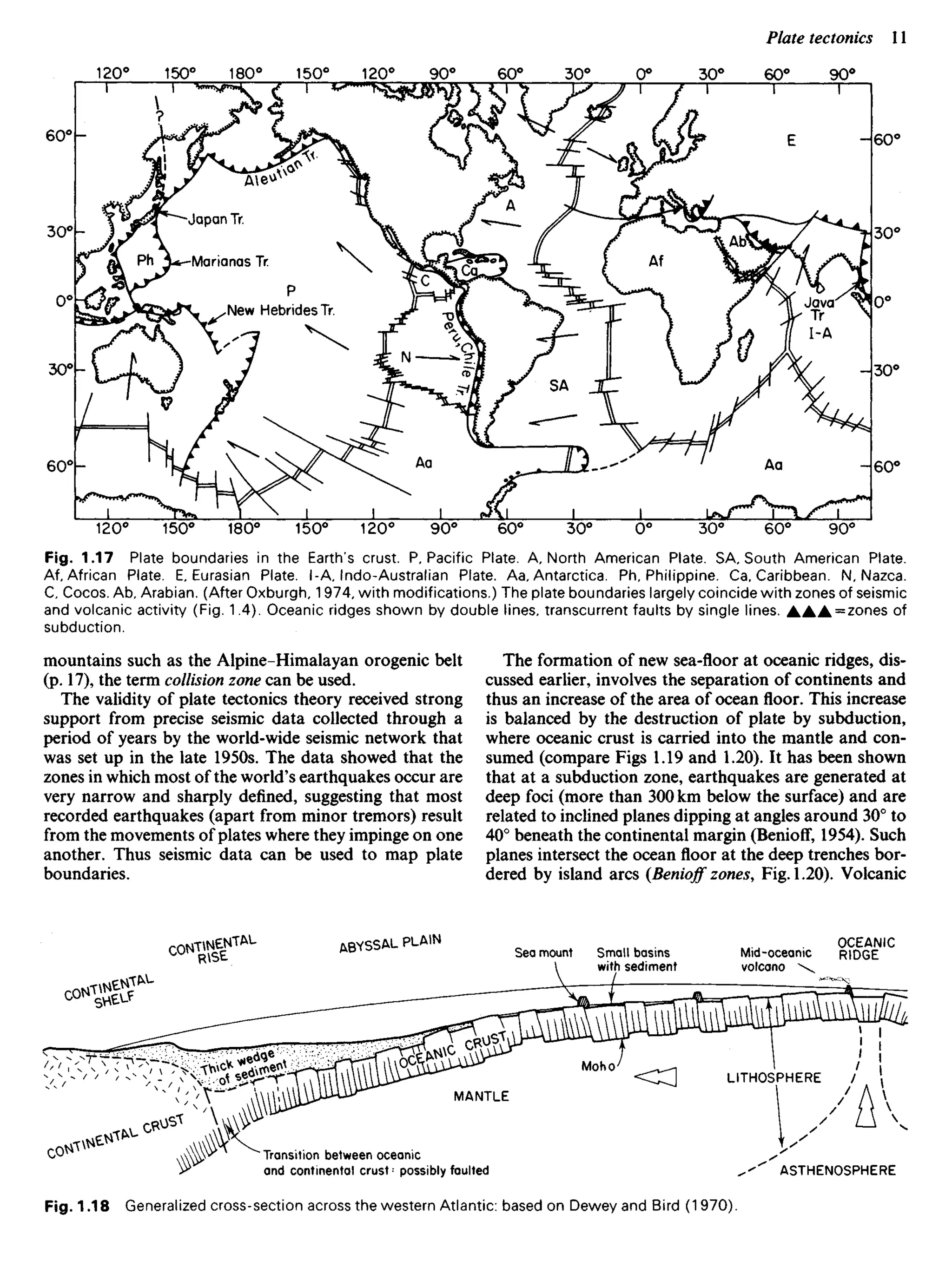
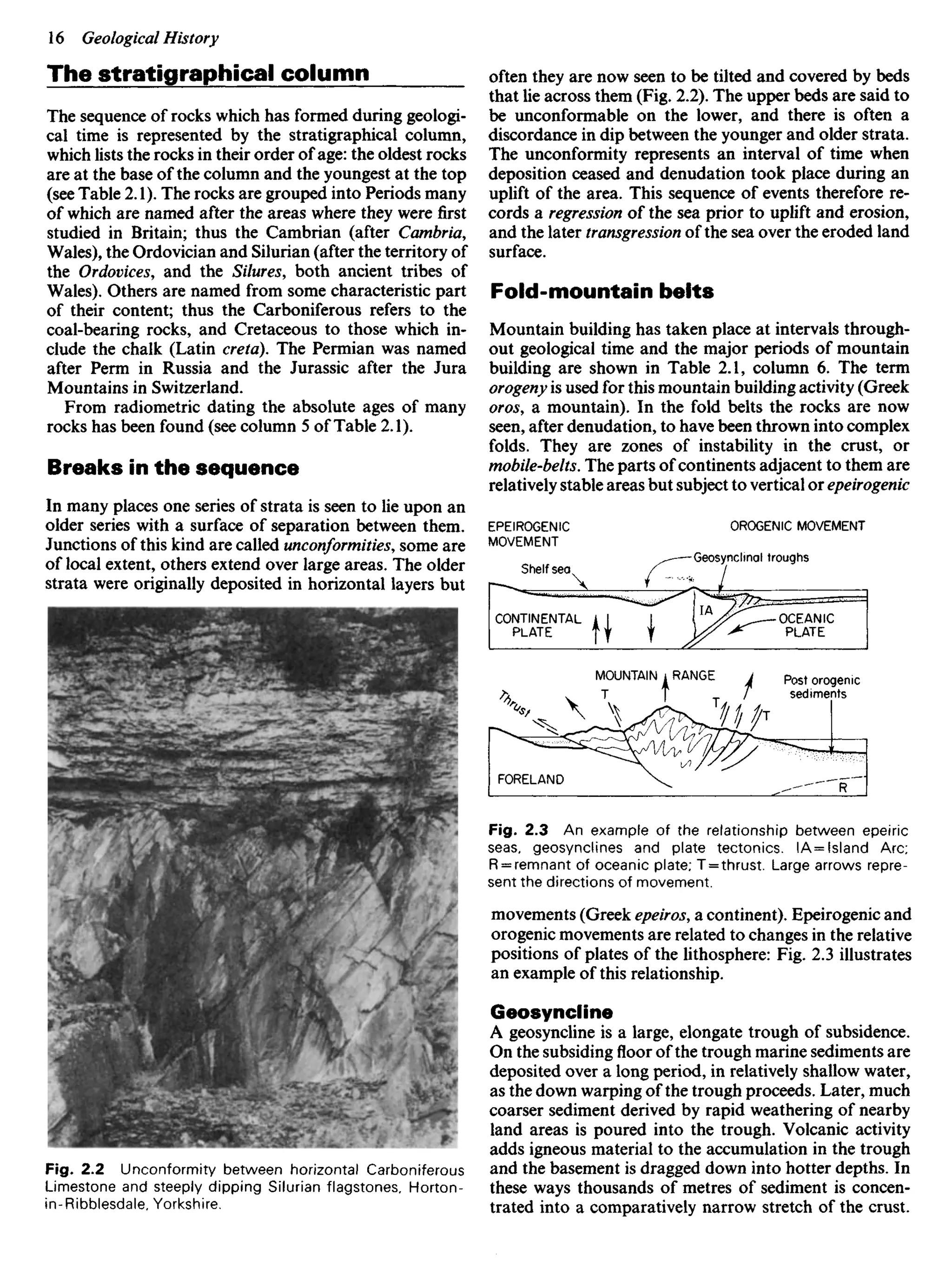
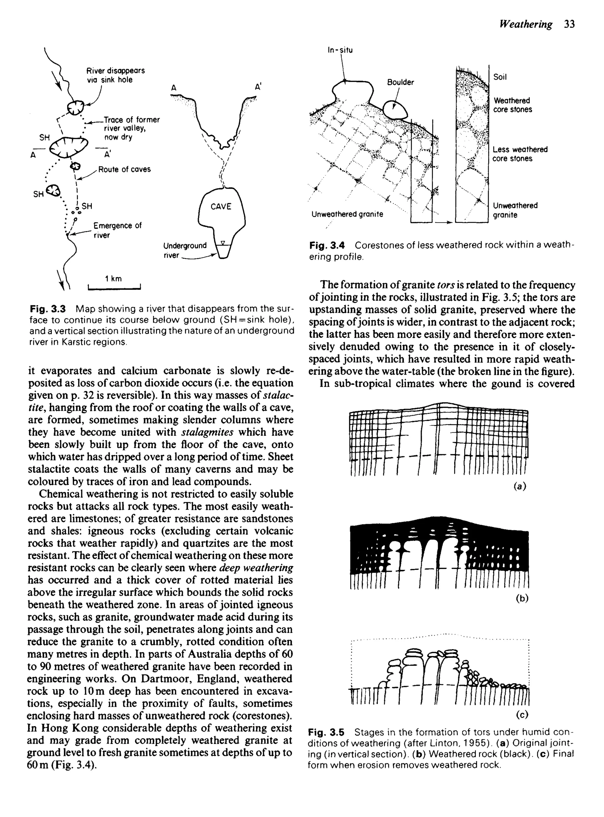
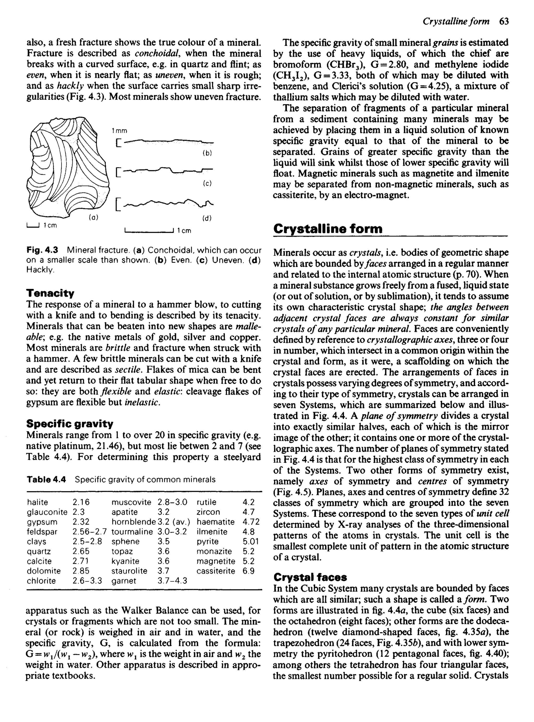
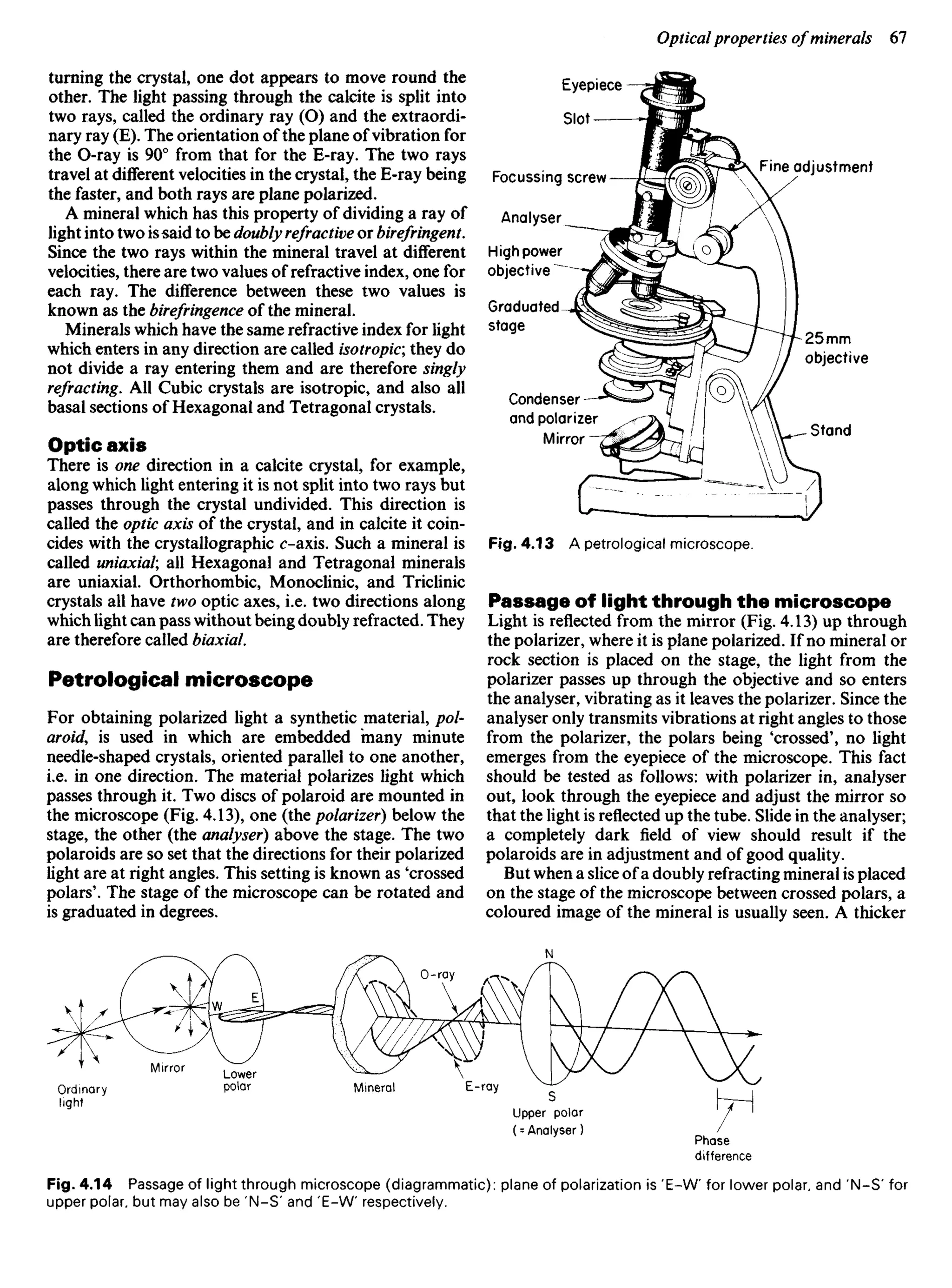
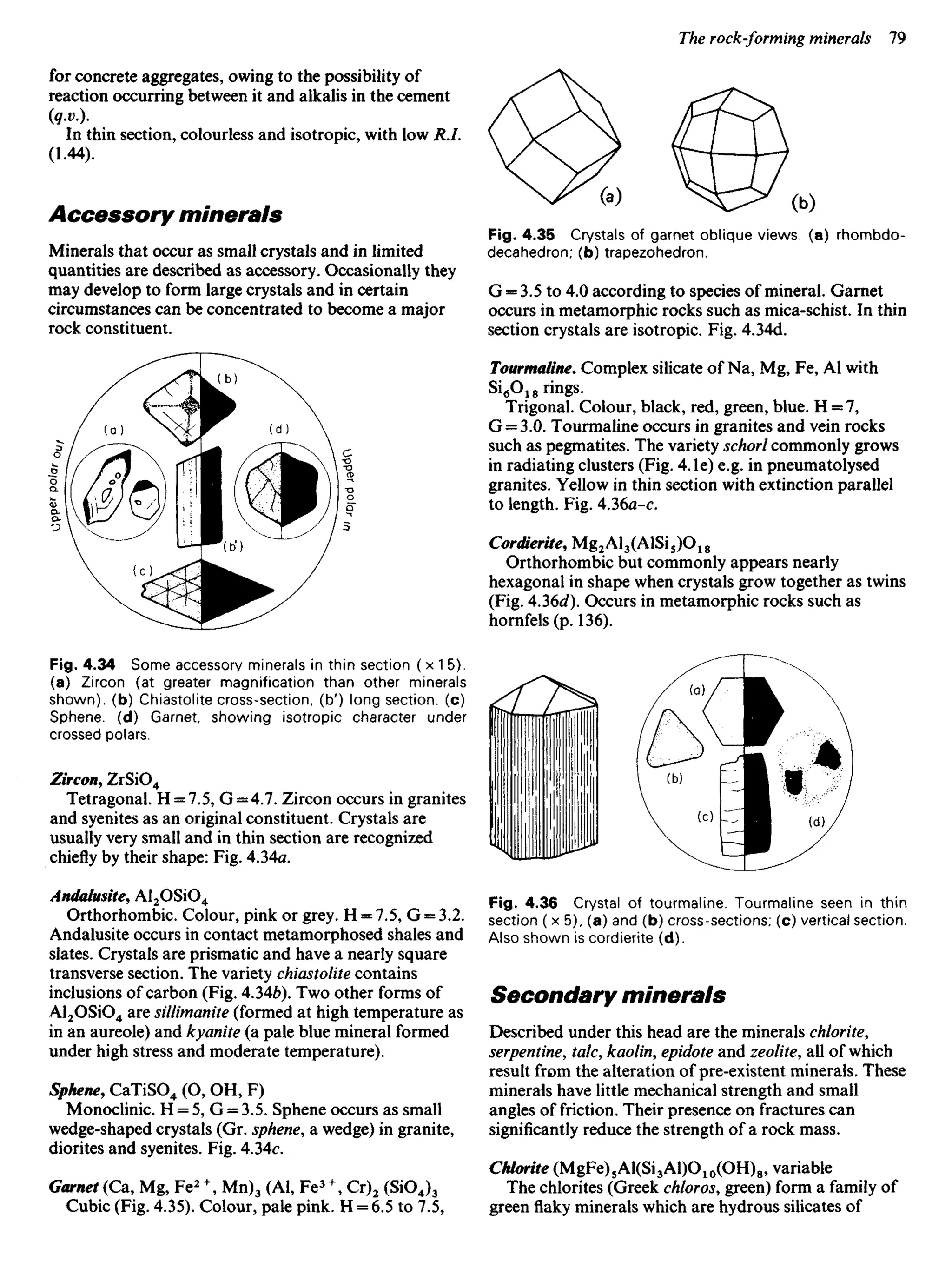
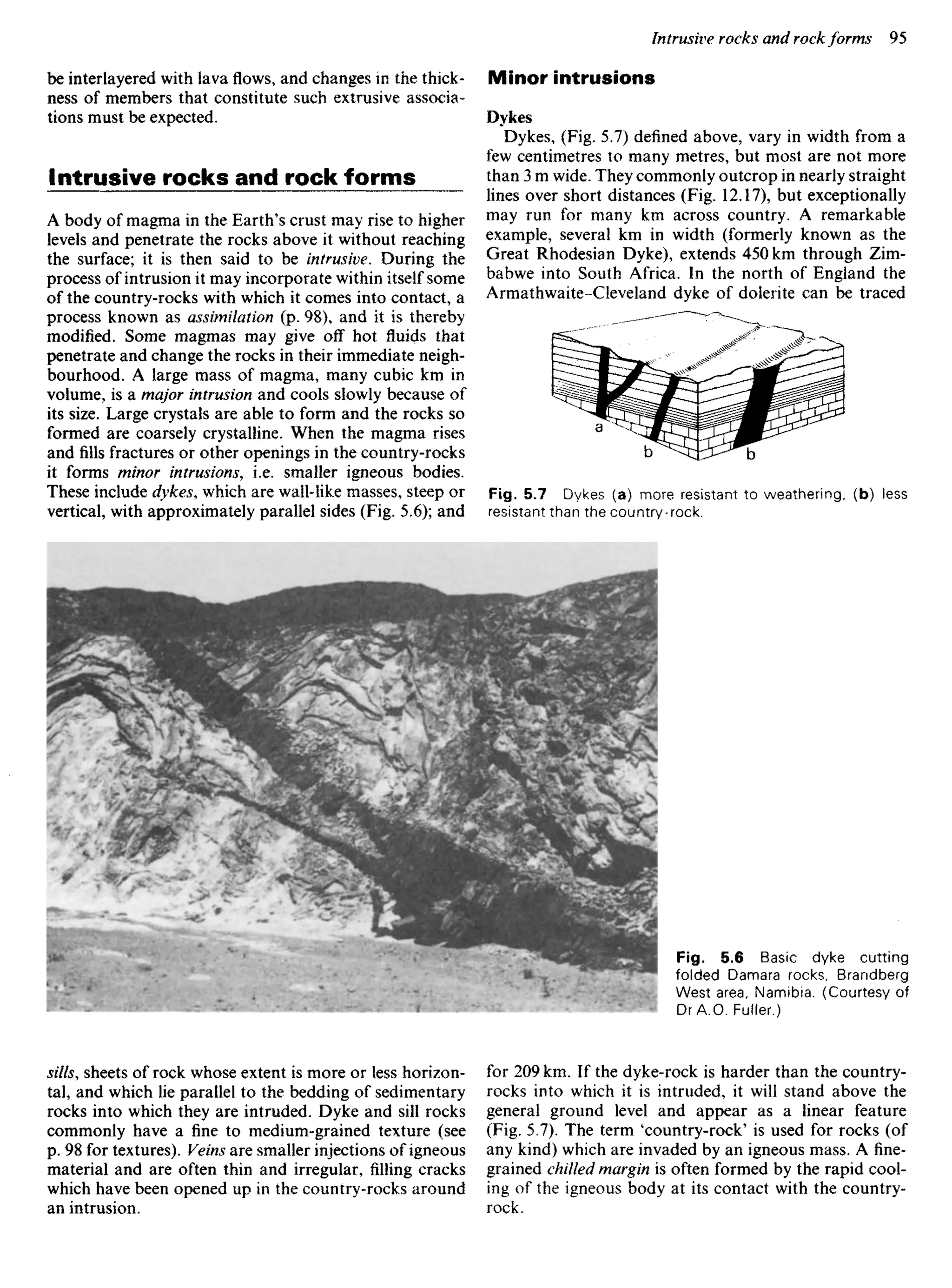
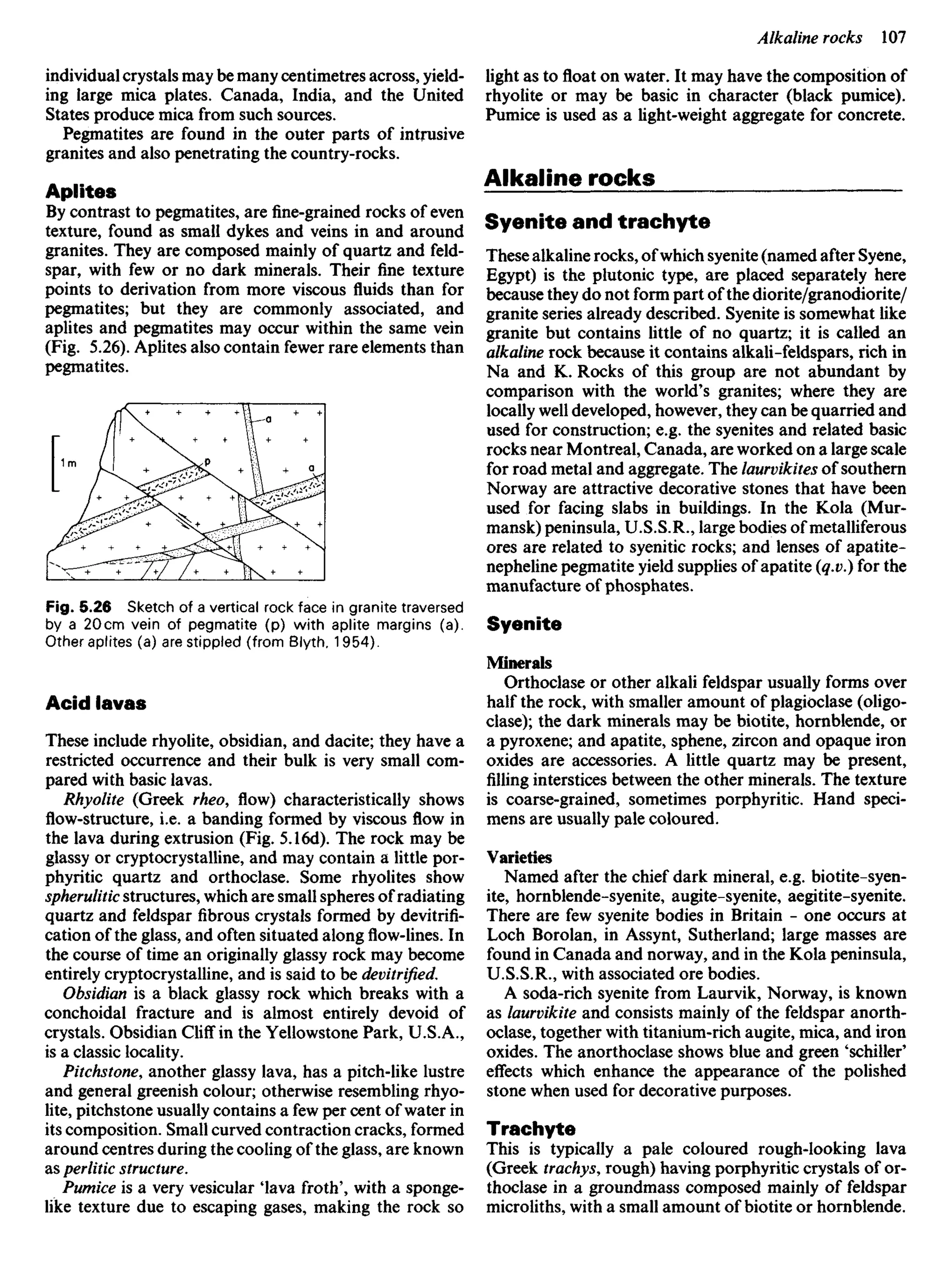
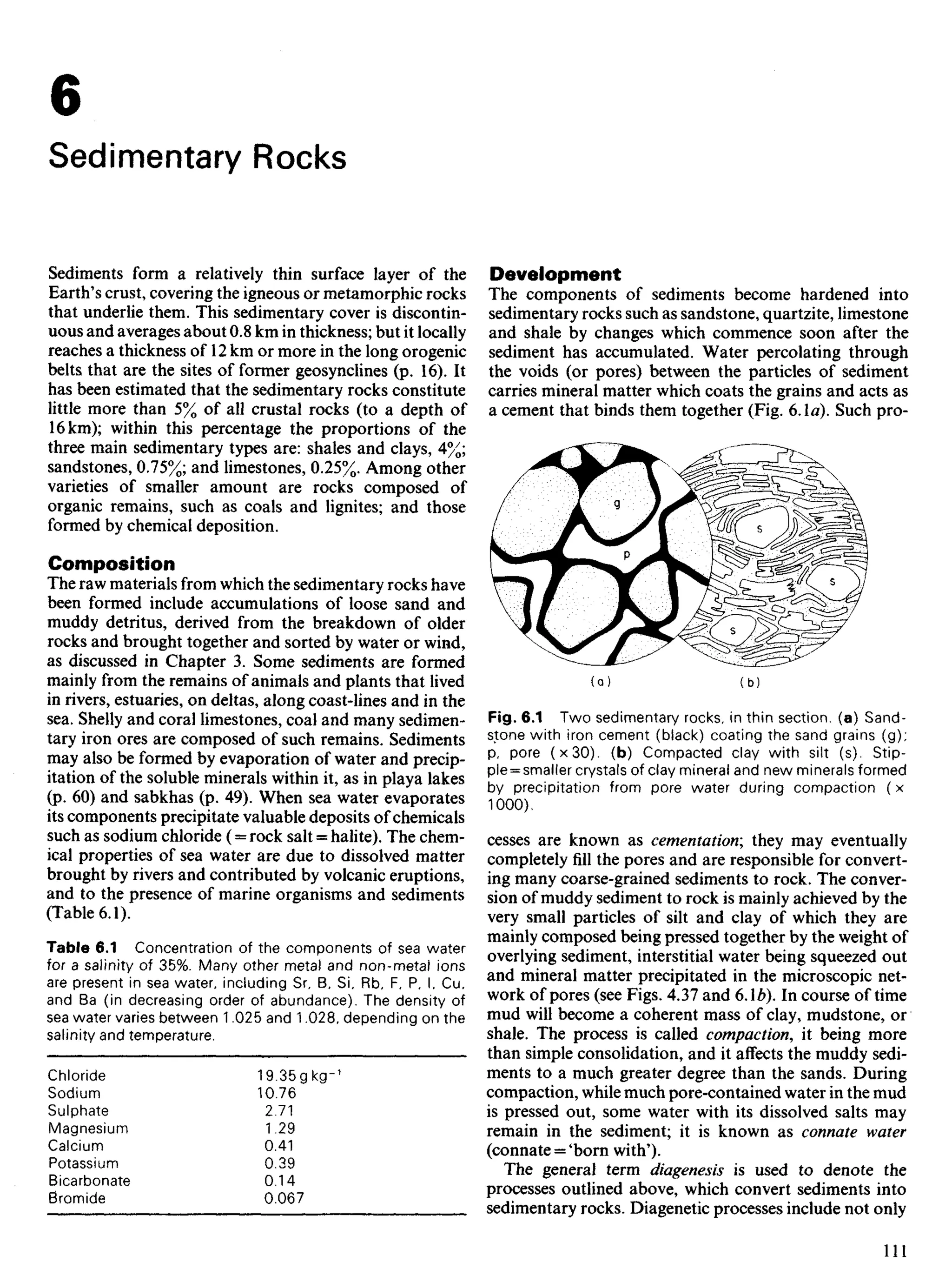
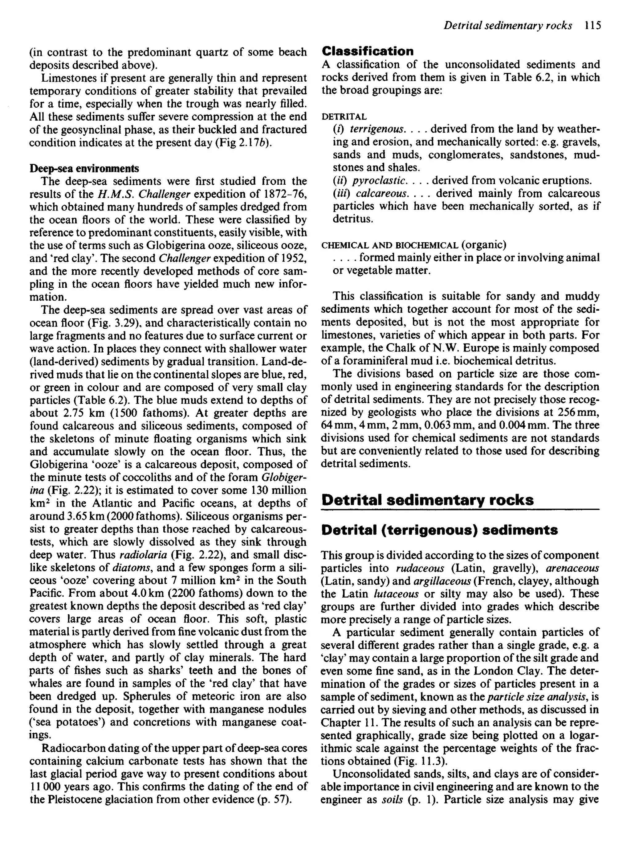
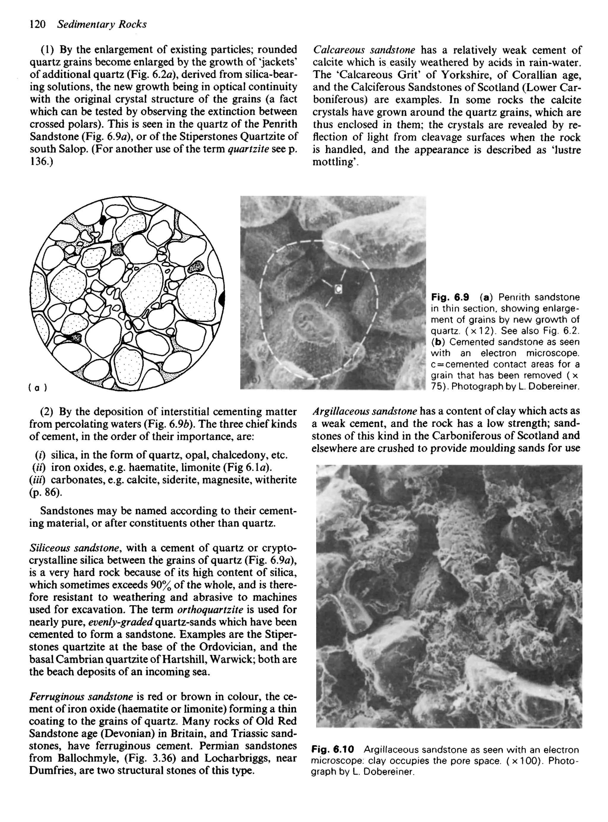
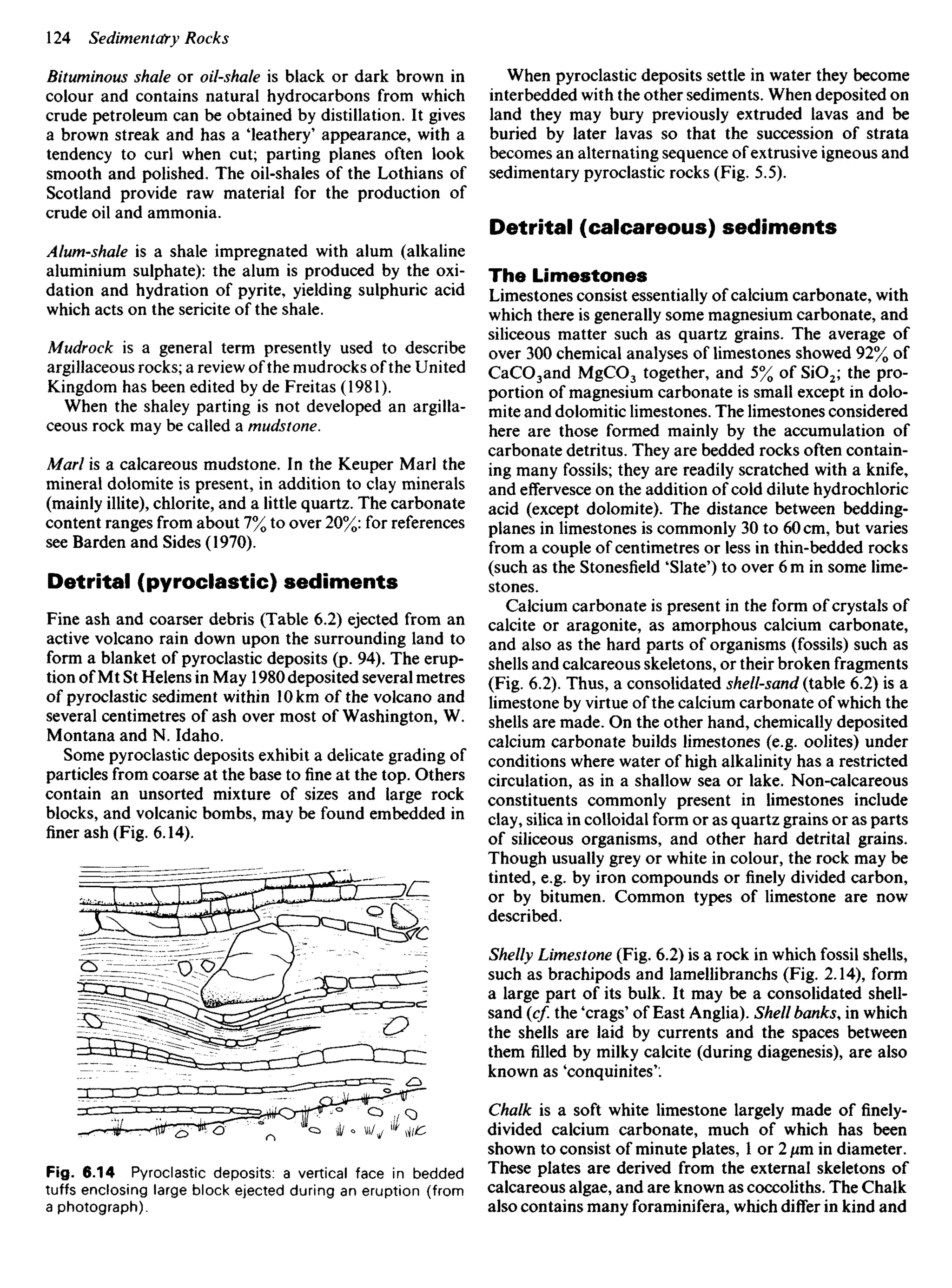
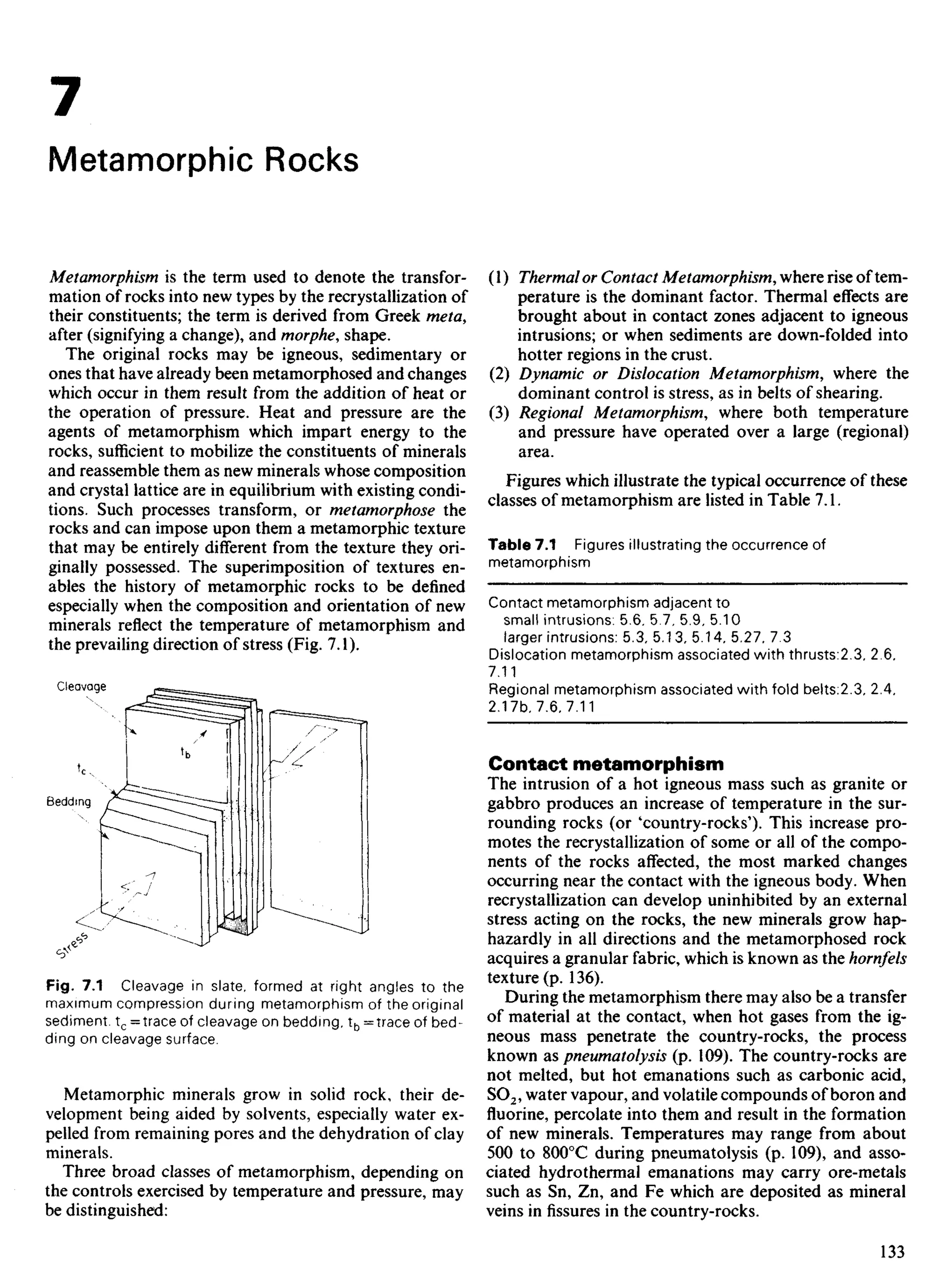
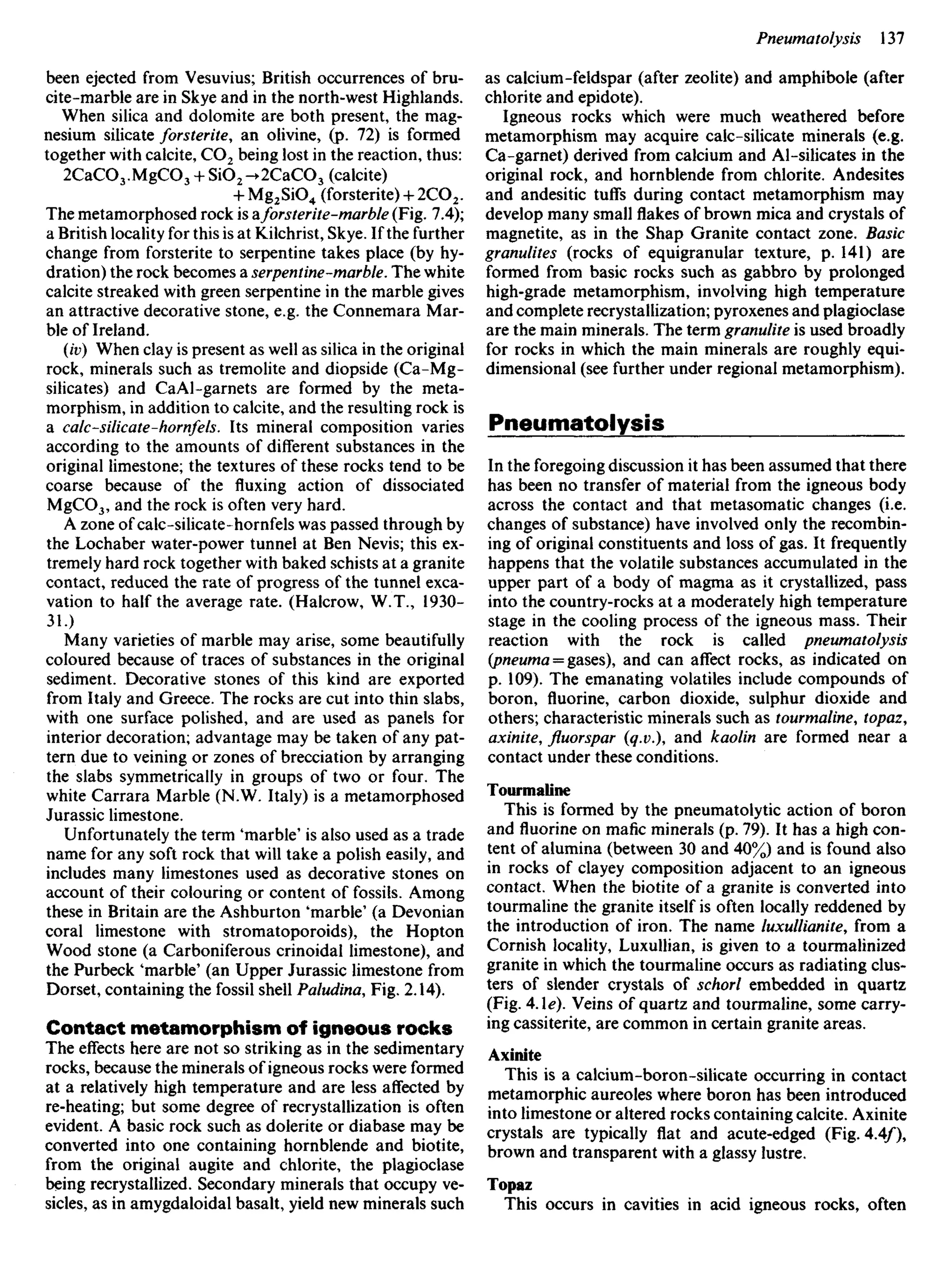
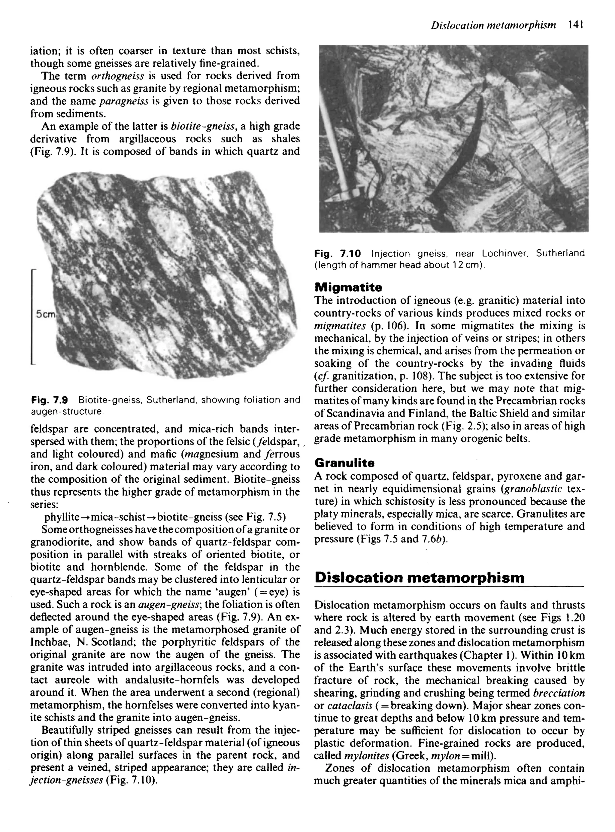
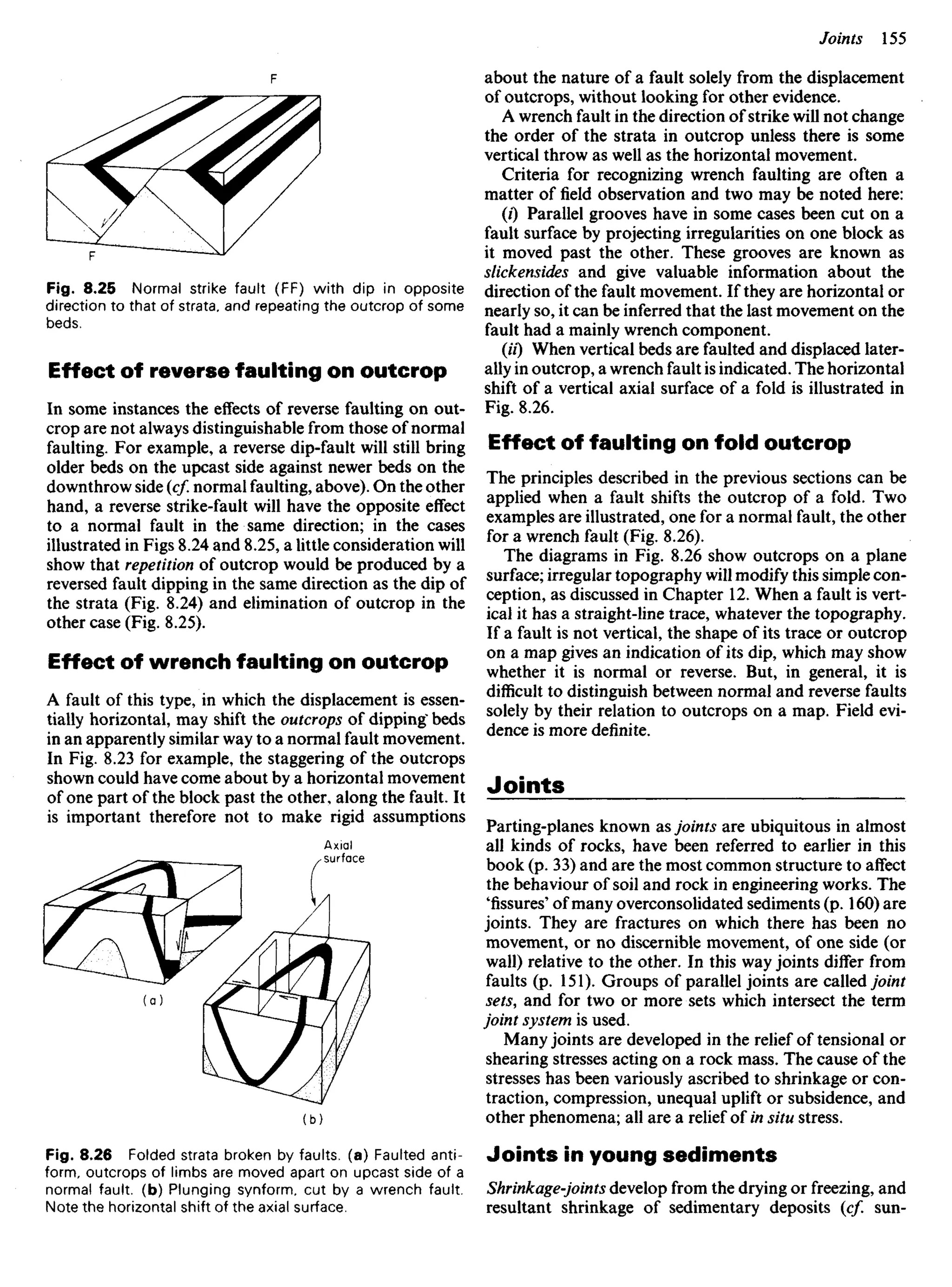
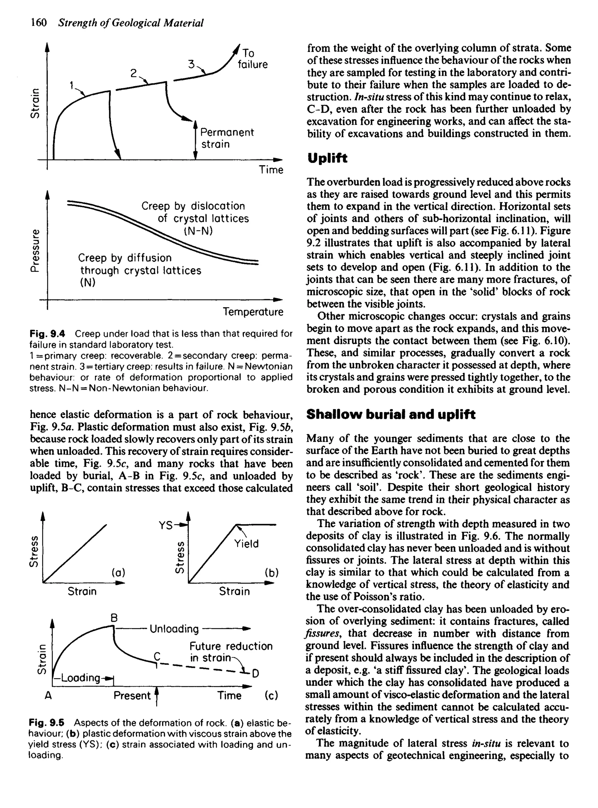
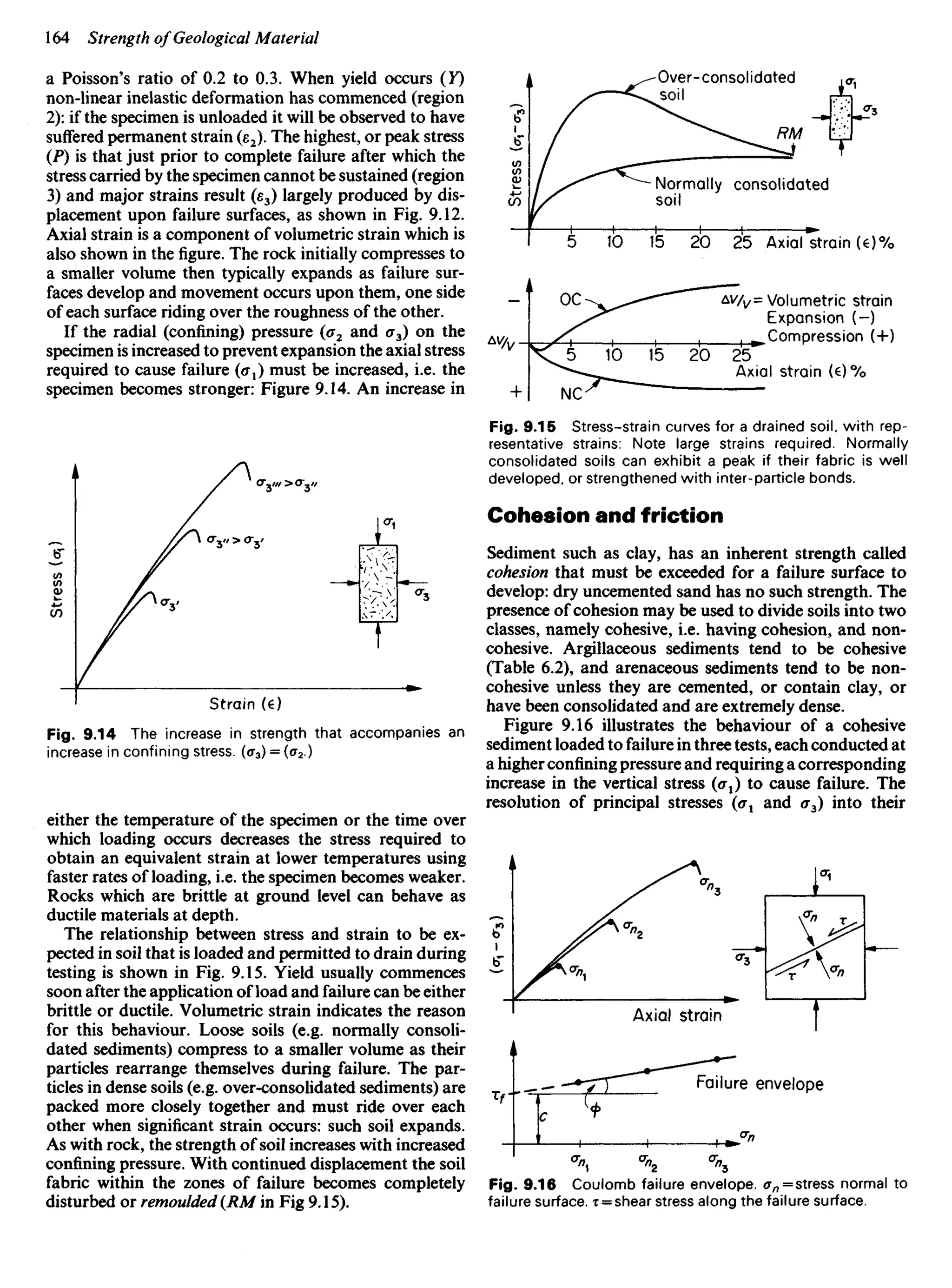
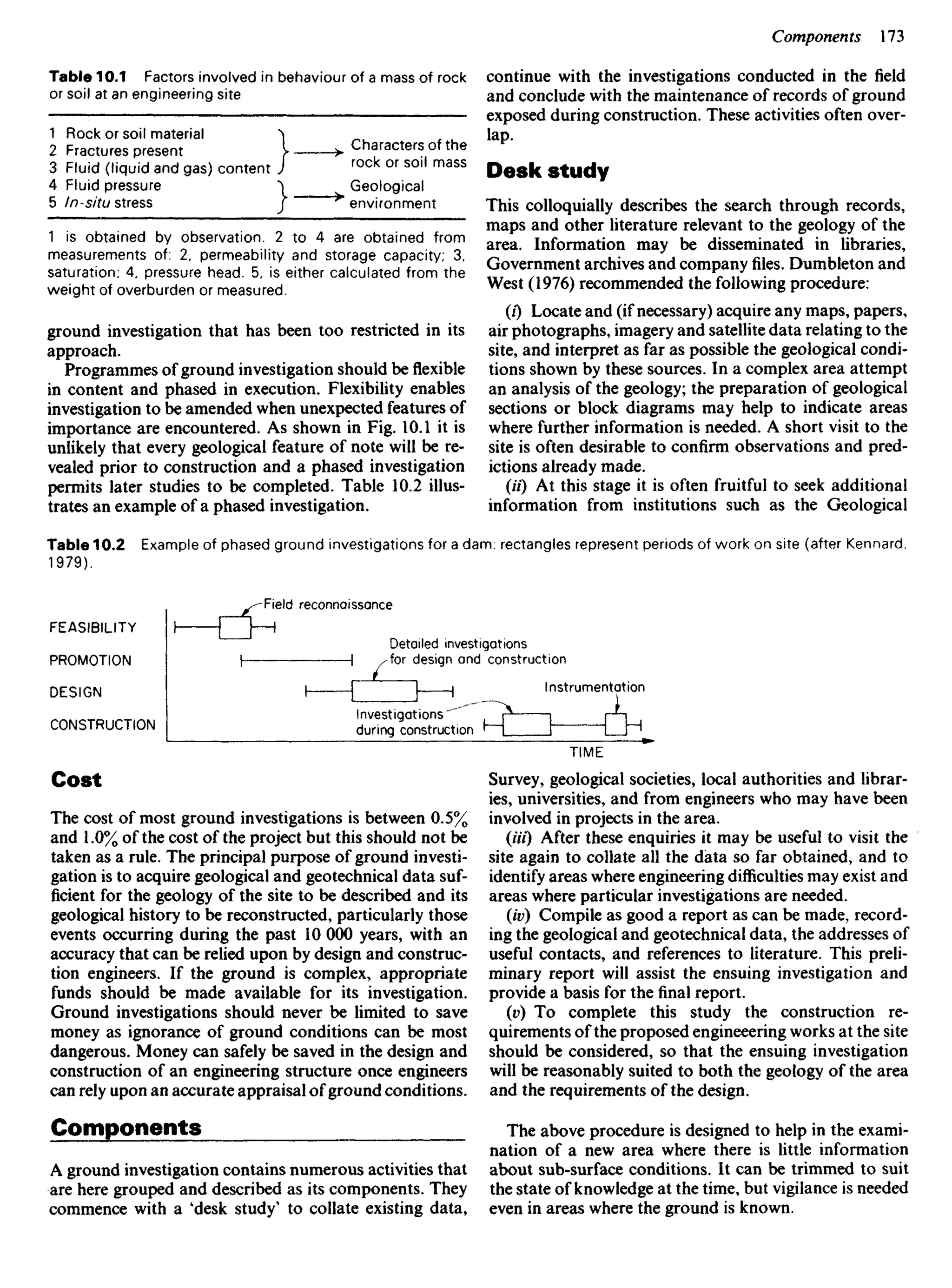
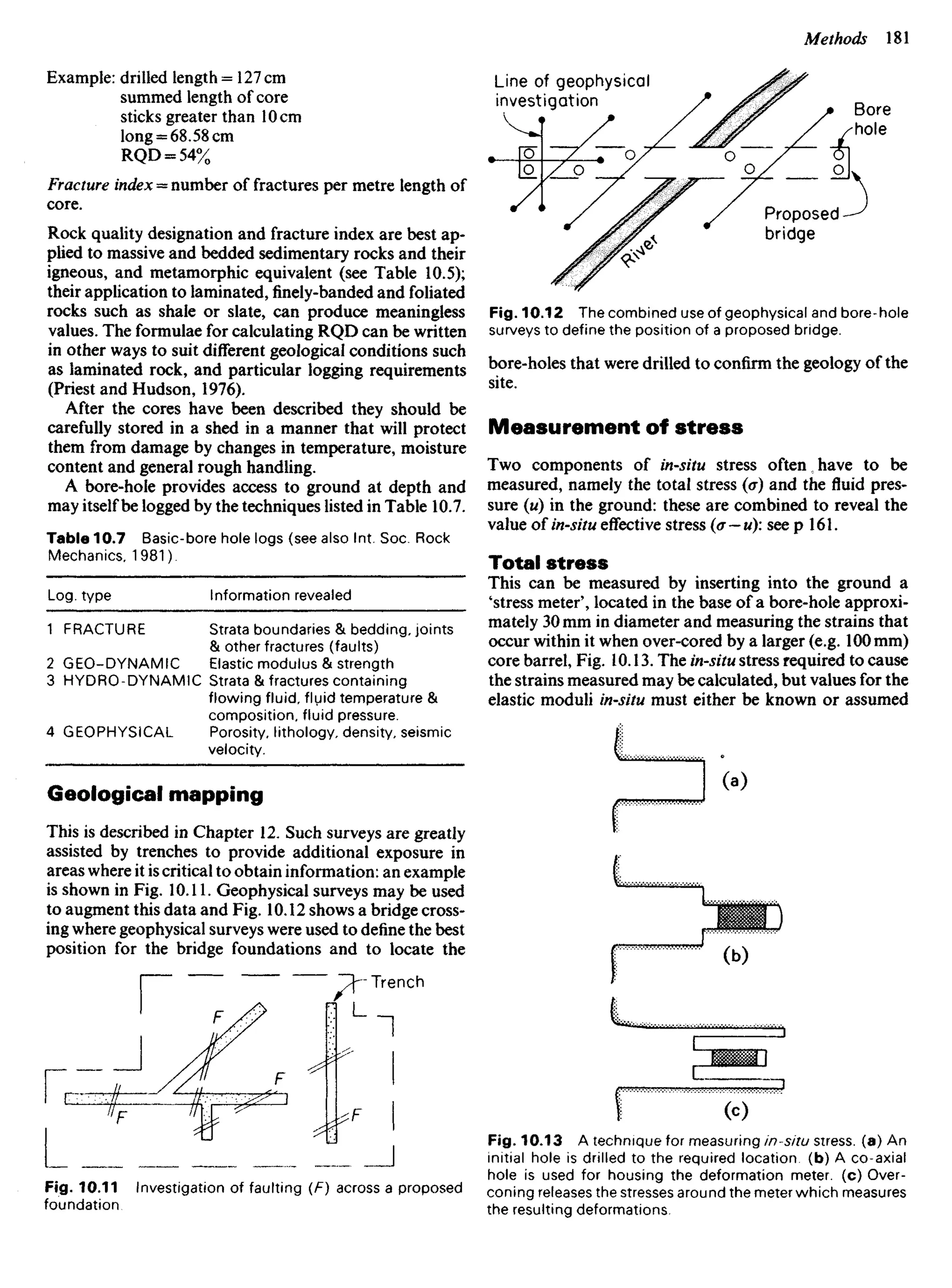
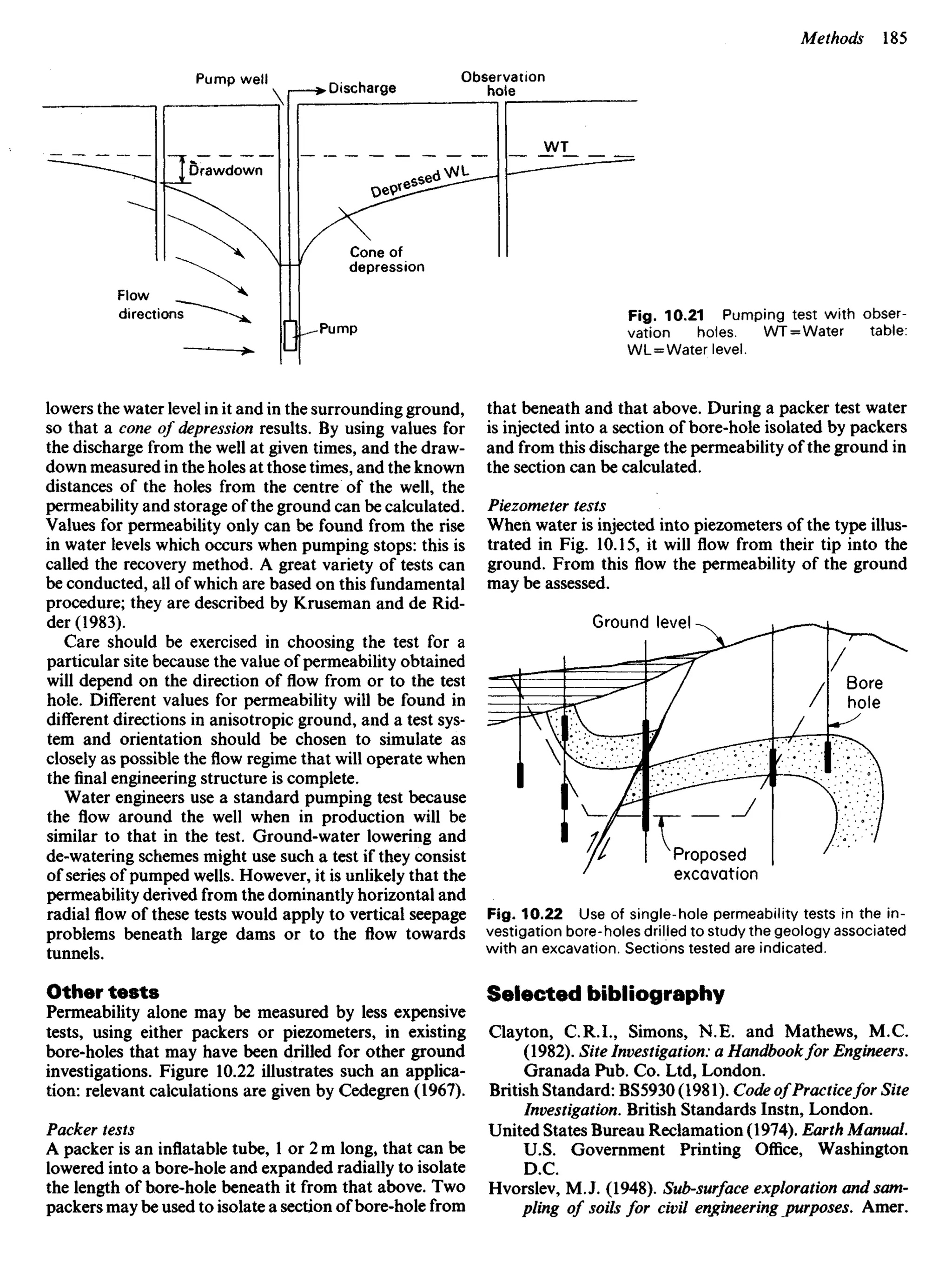
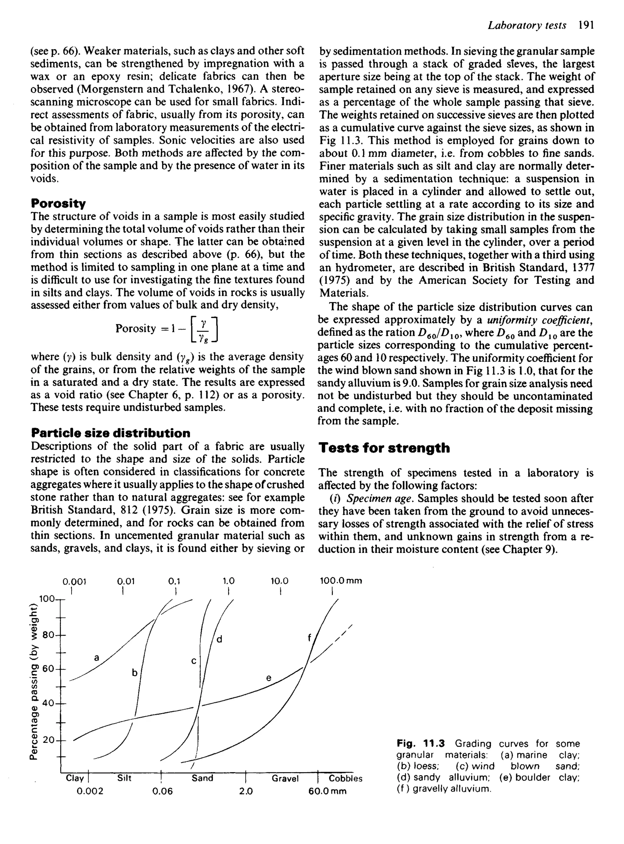
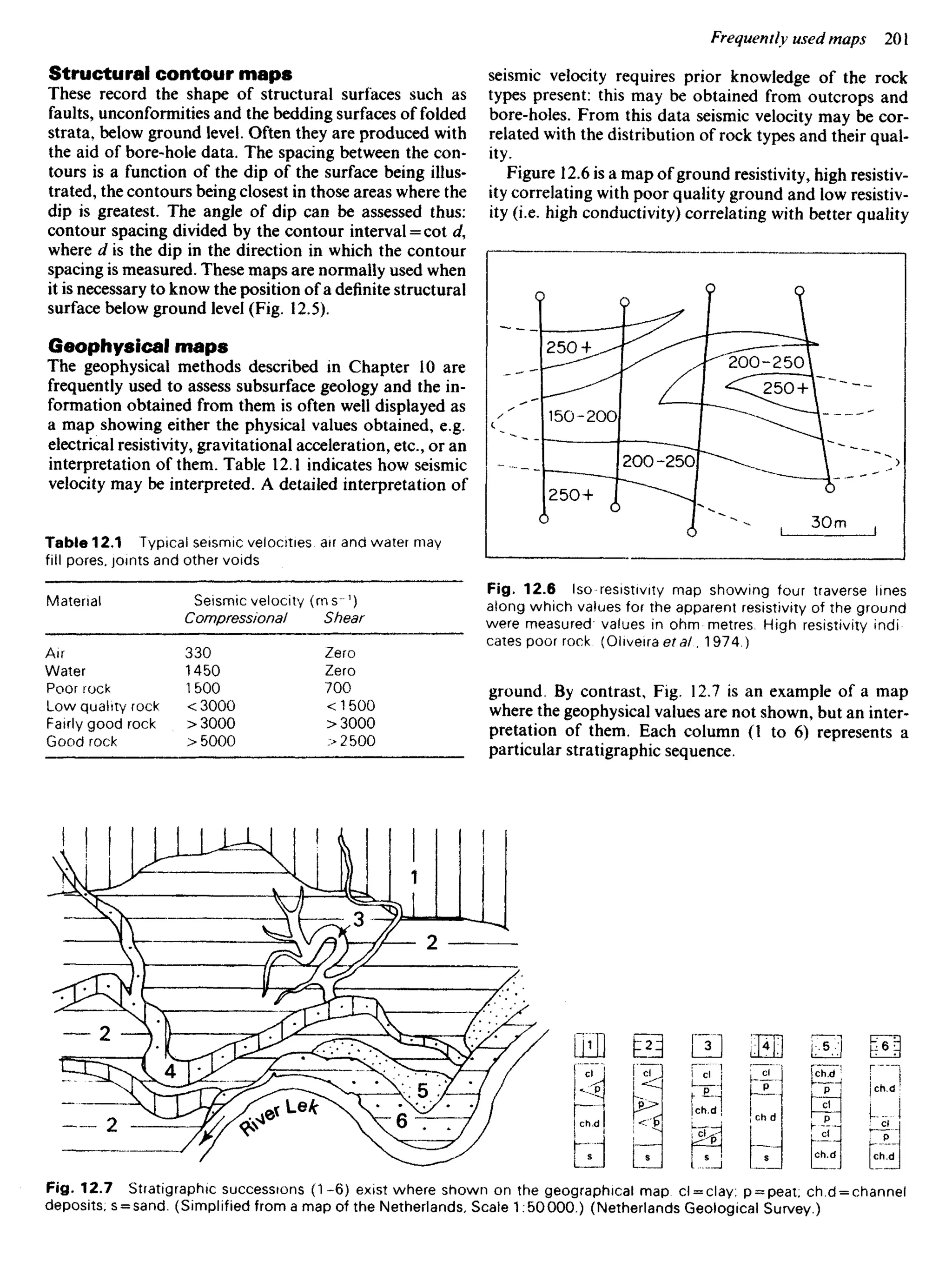
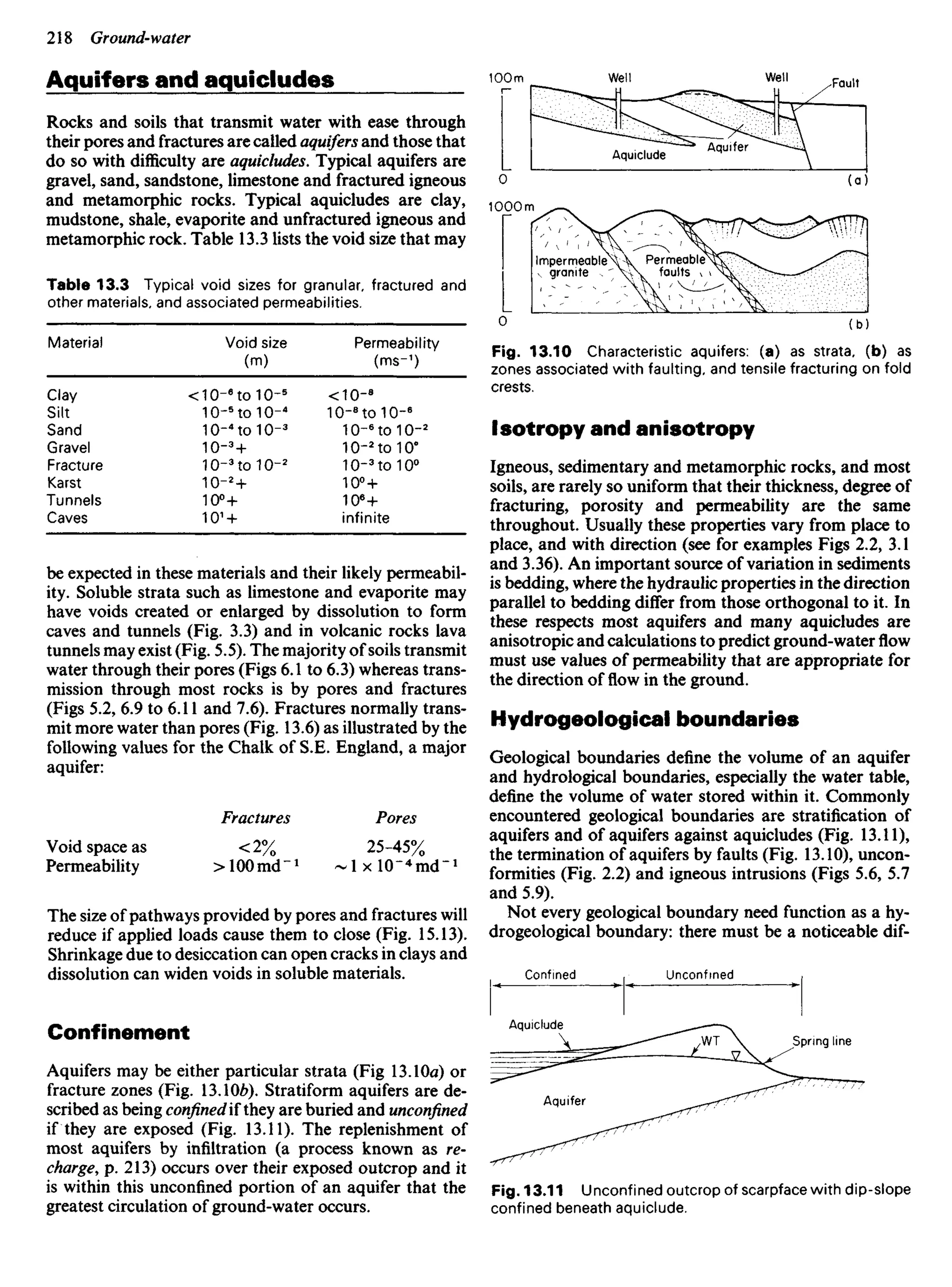
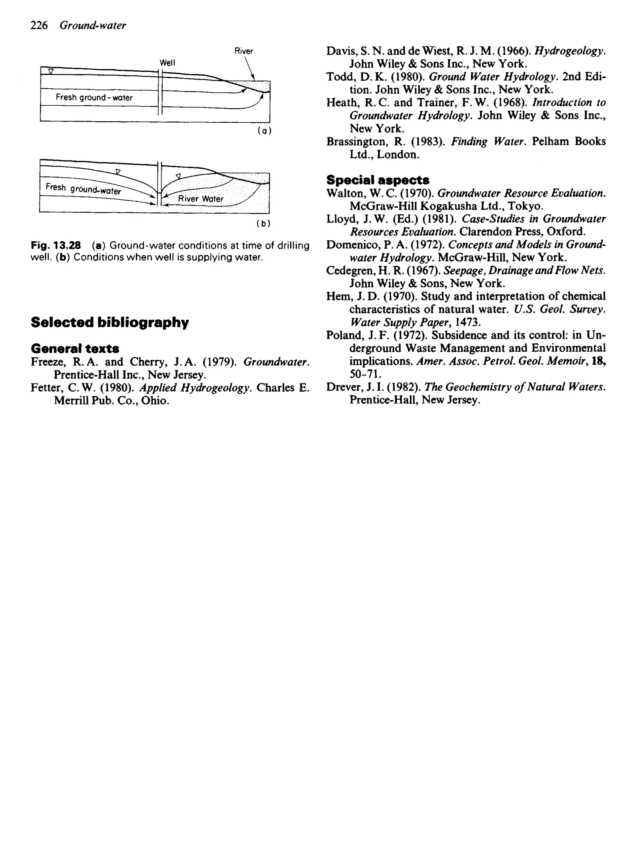
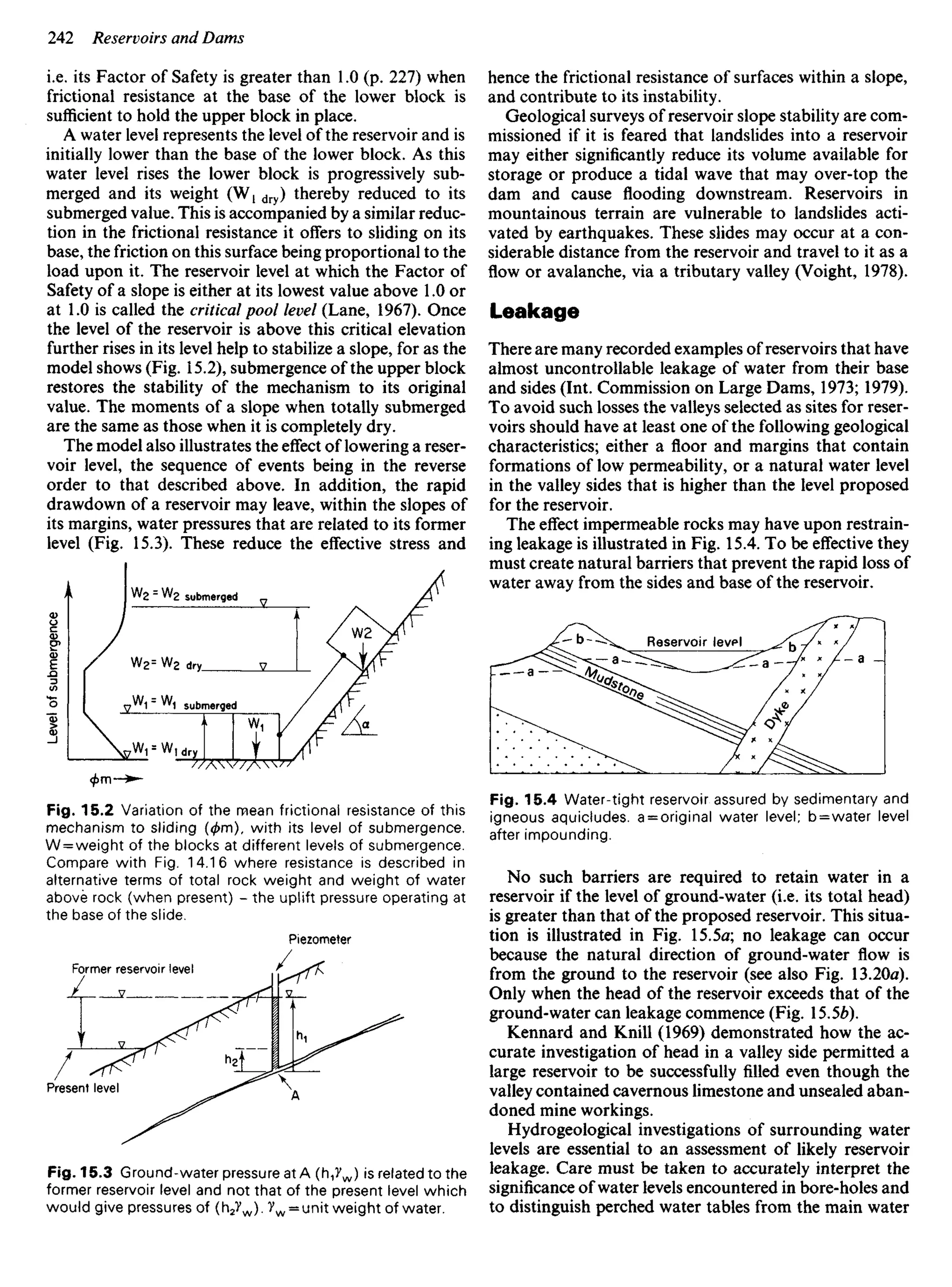
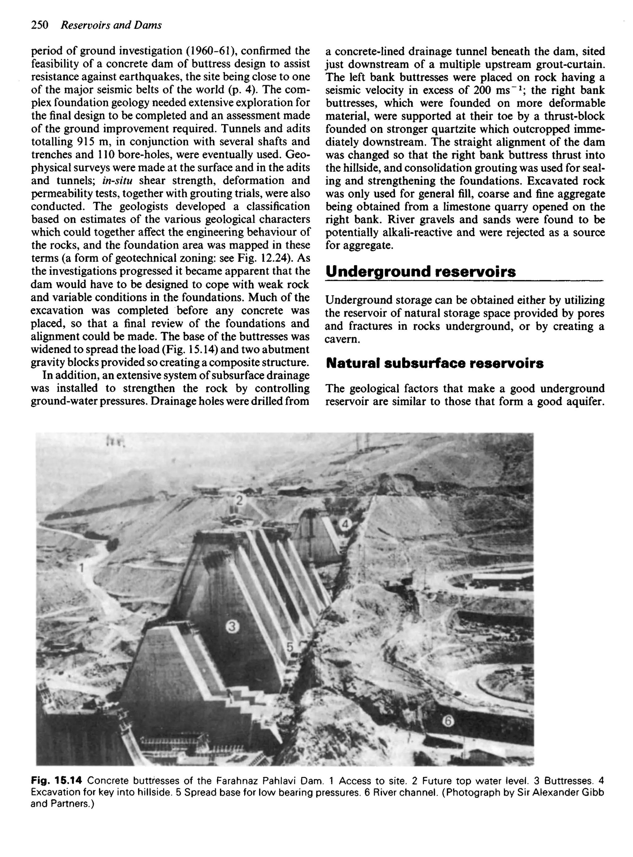
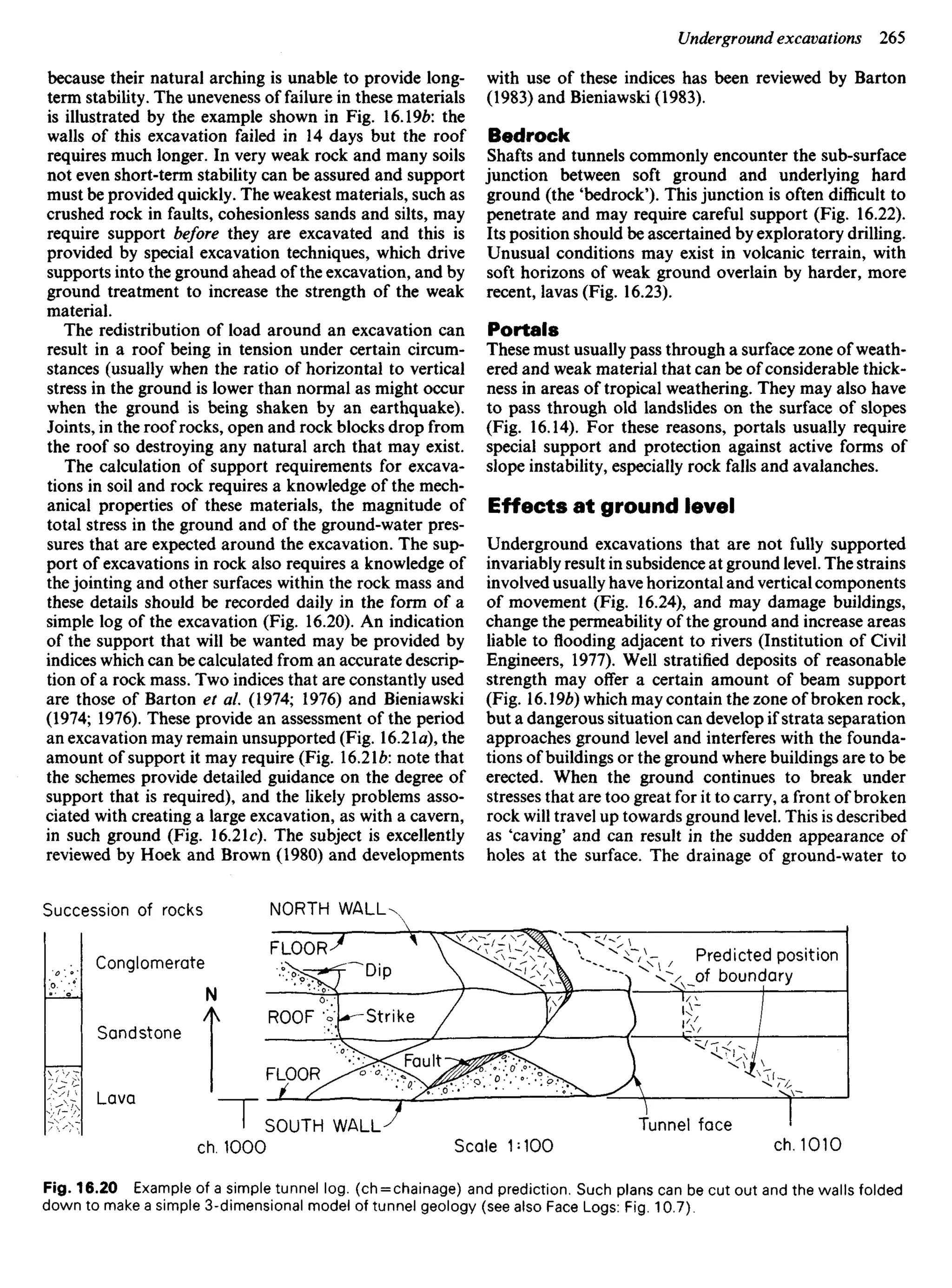
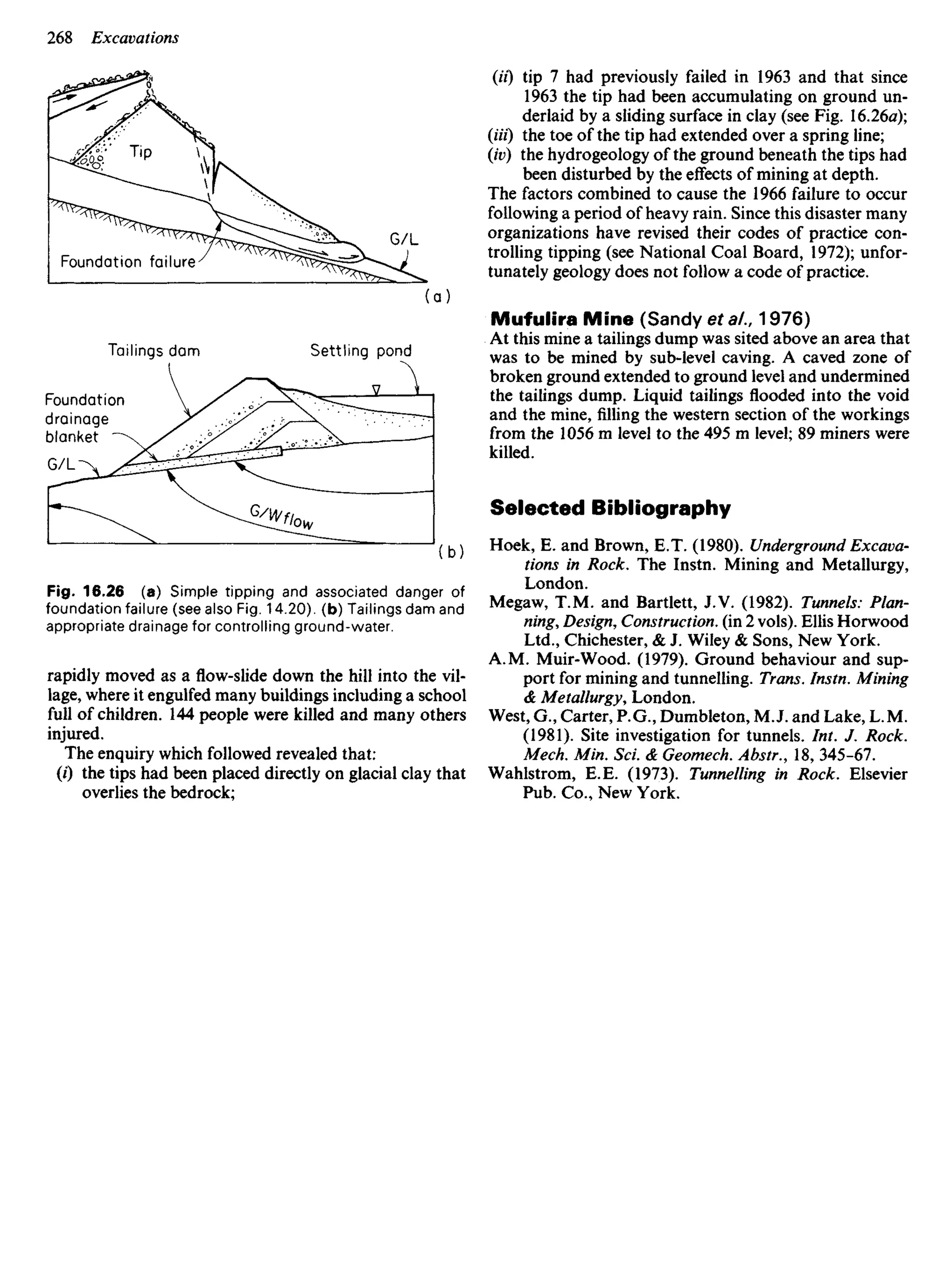
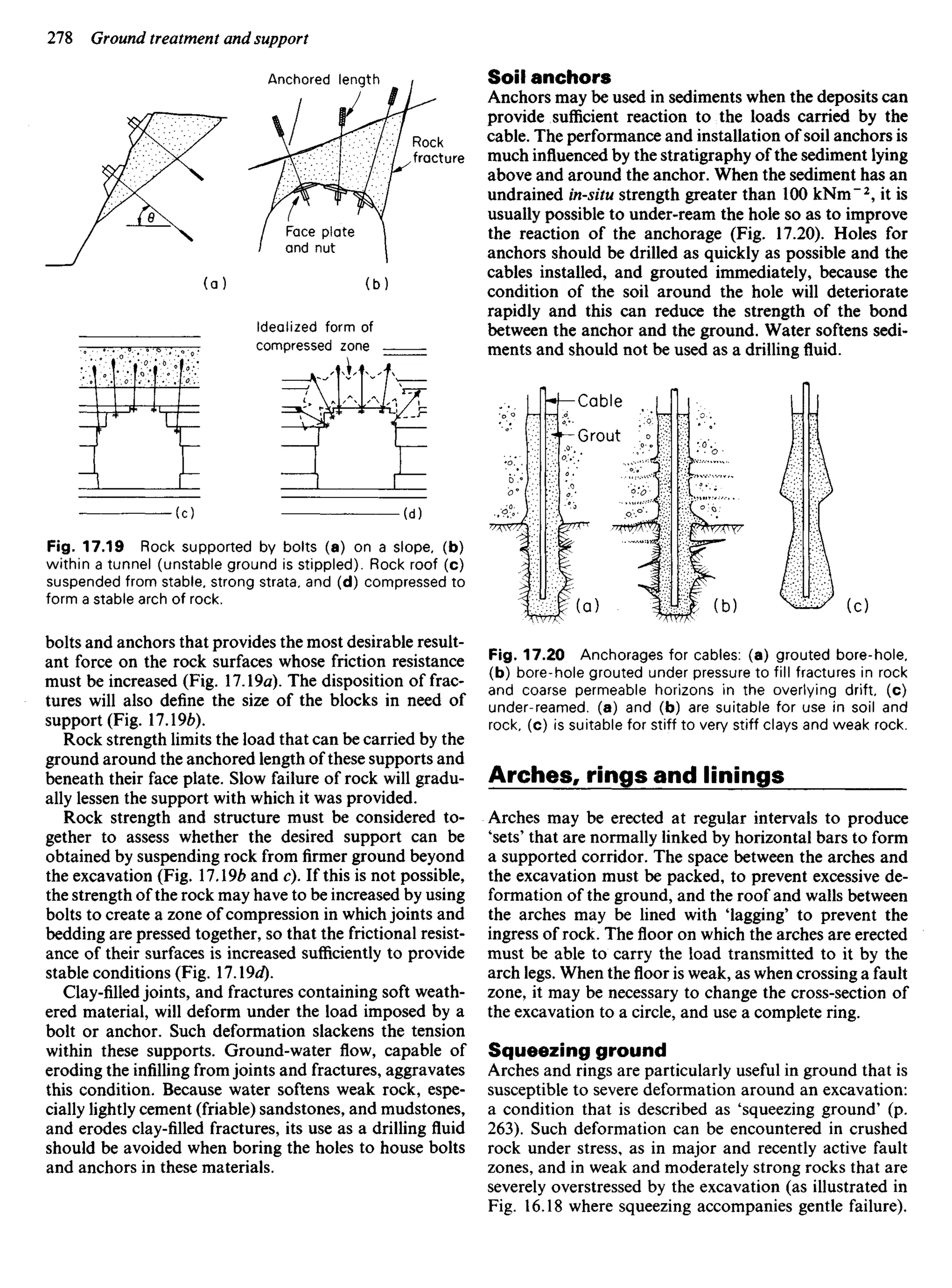
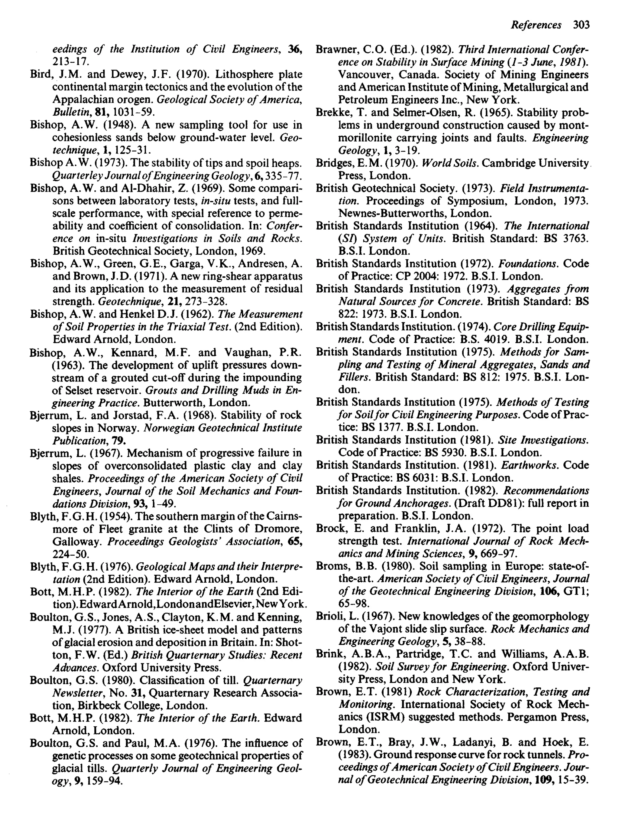
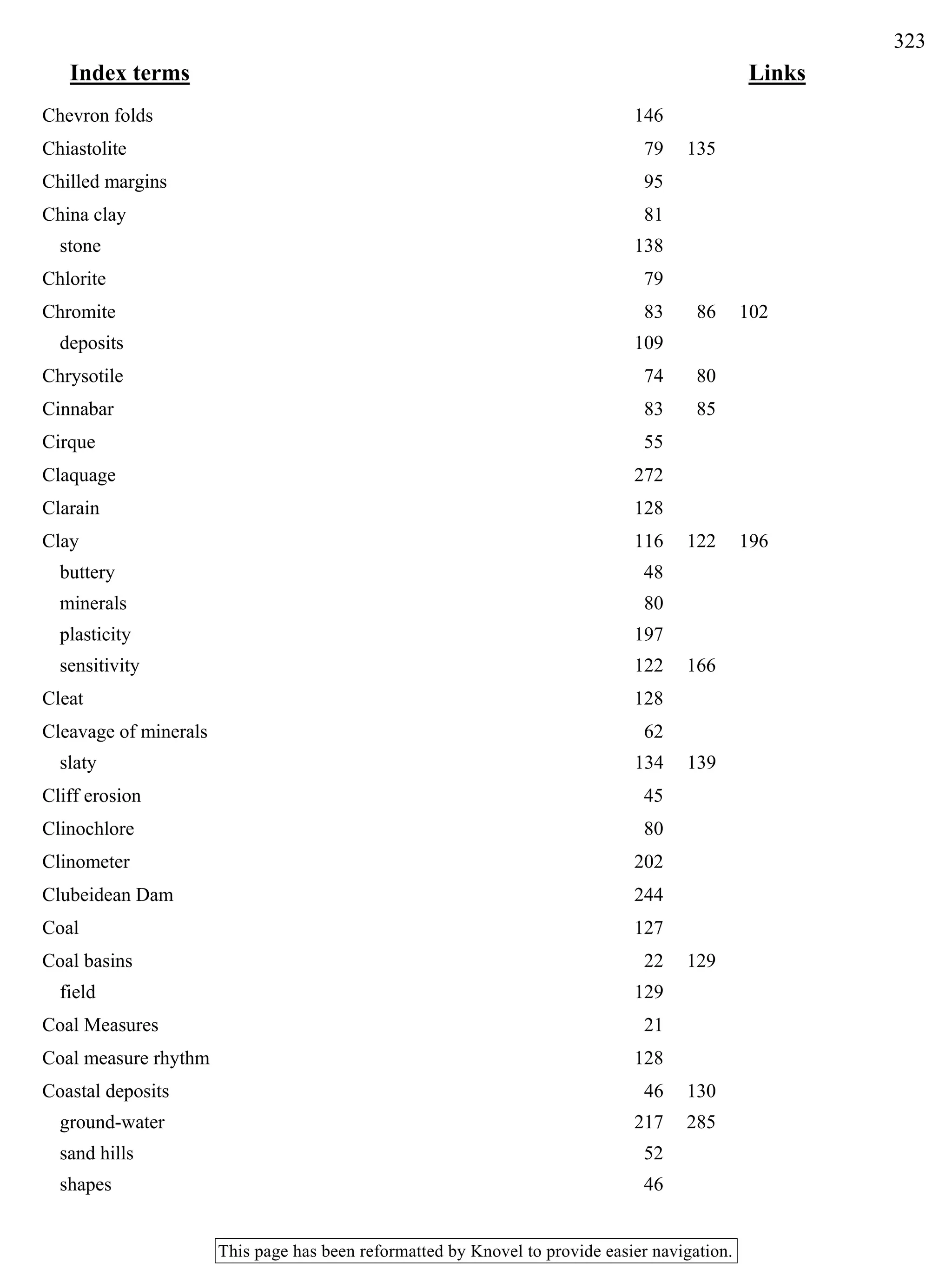
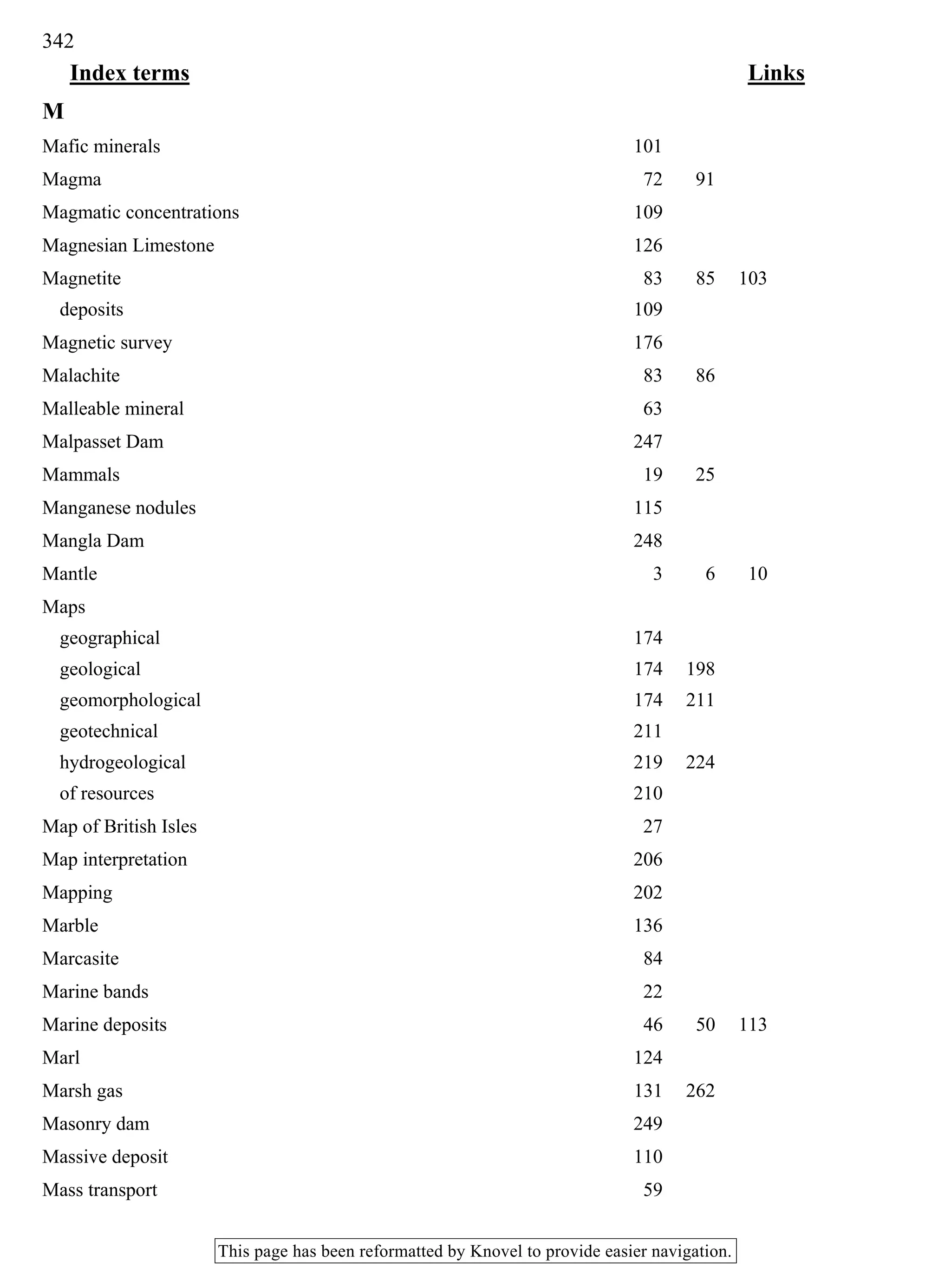
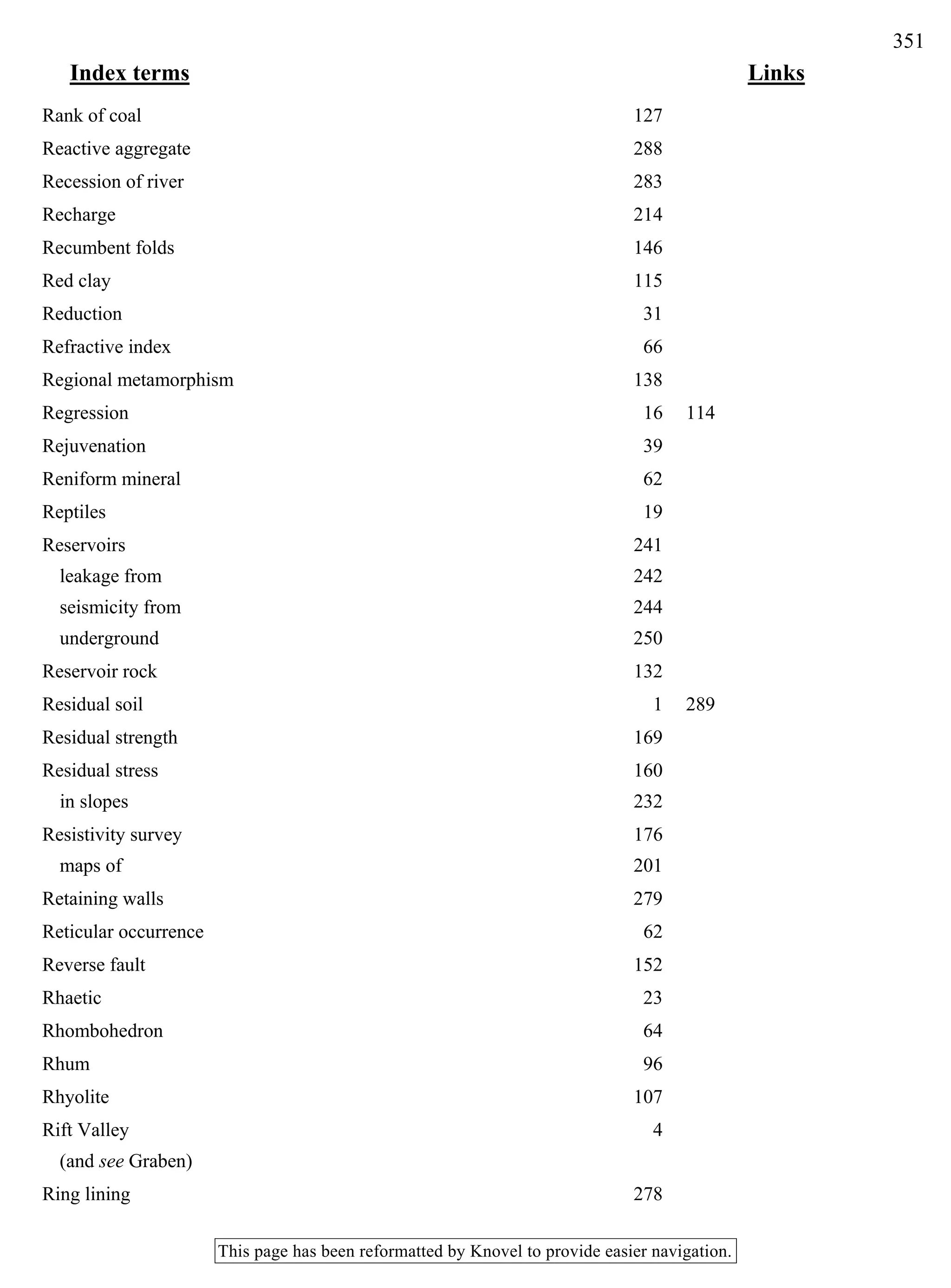
Figure 11.1 illustrates a 20 m deep bore-hole sunk to
investigate the ground beneath a foundation 10 m x 10 m
square. If samples are taken at 2 m intervals, as in the
figure, the volume sampled will be about 1/250 000th of
the ground subject to loading. This example demonstrates
the care required when selecting samples for testing.
Weak strata and zones of weakness in soil and rock
should always be tested. Specimens to be tested in a
laboratory normally have dimensions which prevent
them from containing major surfaces of weakness, such
as joints and fissures, and laboratory tests usually over-
estimate in-situ shear strength. Unavoidable deformation
of the specimen that occurs when it is being recovered
from the ground and prepared for testing, results in most
laboratory tests under-estimating in-situ moduli: (see
Marsland, 1975; and Lessons from Failure, p. 170).
Collection of samples
Changes in moisture content, either by wetting or
drying, can be avoided by sealing the sample with an
impermeable material such as paraffin wax or polythene
(see Stimpson et ai, 1970). This should be done as soon
as possible after the specimen has been collected; samples
should not be collected from areas where the natural
moisture content of the ground has been changed by
wetting or drying.
Loss of material is a hazard in sands, gravels, and
similar deposits which have little or no cohesion and
should be avoided. Comparatively undisturbed samples
of moist sand may be taken from natural exposures,
excavations, and borings, above the water table, by gently
forcing a sampling tube into the ground. Samples are less
easily obtained below the water table, and if they are to
be taken from a bore-hole, the water level in the hole
should be kept higher than that in the adjacent ground.
The flow of water outward from the bore-hole will then
tend to prevent the loss of finer particles which would
otherwise be flushed from its sides by inflow of water
from the surrounding ground. Having obtained a sample,
loss of material from it should be avoided during its
transport to the laboratory. These problems are less
severe when dealing with rocks than with weak materials
and drilling fines, which should be handled with special
care.
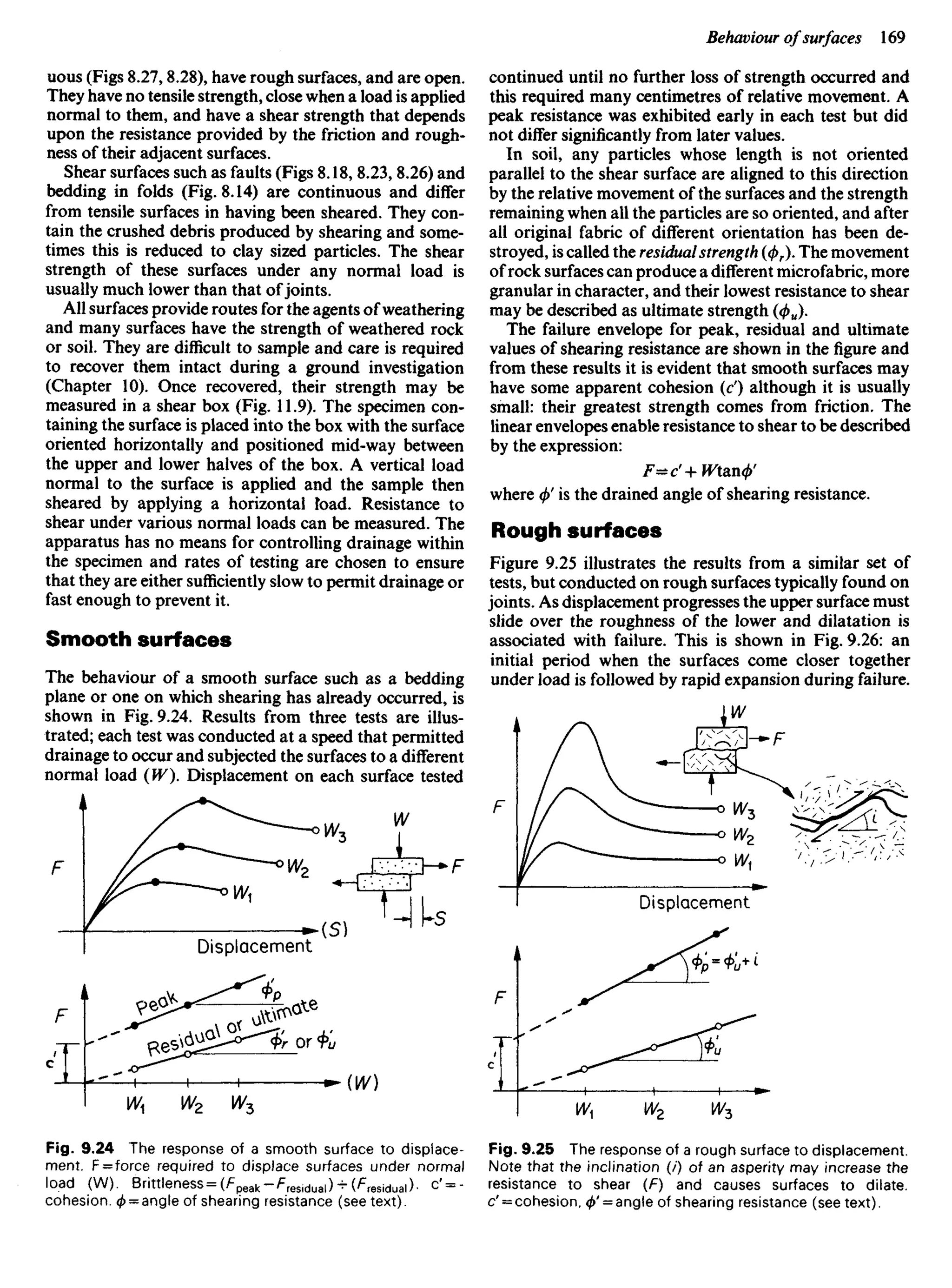
Local over-stressing often occurs with the trimming
and transport of soft materials such as soils. Disturbance
from trimming is affected by the sampling and cutting
tools that are used, and cutting edges should be sharp so
as to cut smoothly and cleanly. They should also be thin
so that they cause little displacement when passing
through the soil. This is important in the design of tubes
that are pushed into the ground to collect a sample; an
area ratio of the form
Da2
- Db2
I
[-5ST-] xI00%
should be observed, where Da is the outside diameter of
the cutting edge, and Db its inside diameter. The above
represents the area of ground displaced by the sampler in
proportion to the area of sample. Severe disturbance is
likely to occur on the margins of a sample if the ratio is
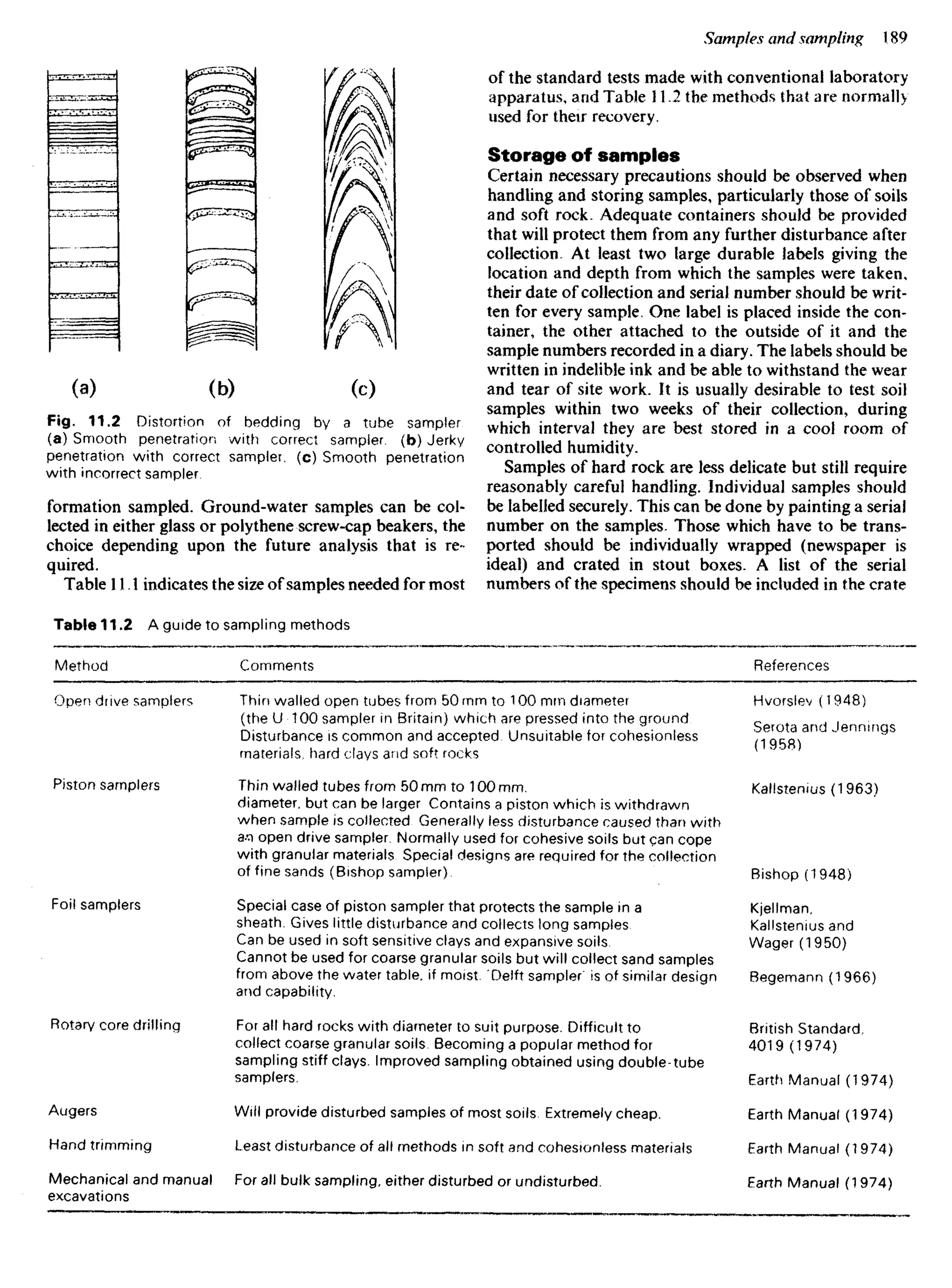
greater than 25%, as illustrated in Fig. 11.2.
Disturbance can also occur during the extrusion of
samples either from sample tubes or core barrels, and
care should be taken that the friction between the sample
and sampler wall is kept as low as possible, and that
excessive pressure is avoided during extrusion. Harder
materials such as rocks can be sampled by coring, as
described in Chapter 9. Hand specimens of rocks should
be at least (8 cm)3
to (10 cm.)3
and representative of the
Future foundation Ground !eve!
Borehole with
100mm dia x
200 mm samples
every 2 m
Stressed ground
Fig. 11,1 Some limitations with sampling. The total volume
of samples is approximately 1/250000th of the stressed
ground. See also Fig. 10.1.](https://image.slidesharecdn.com/ageologyforengineersseventhedition-240123054612-a0c16209/75/A_Geology_for_Engineers_Seventh_Edition-pdf-172-2048.jpg)


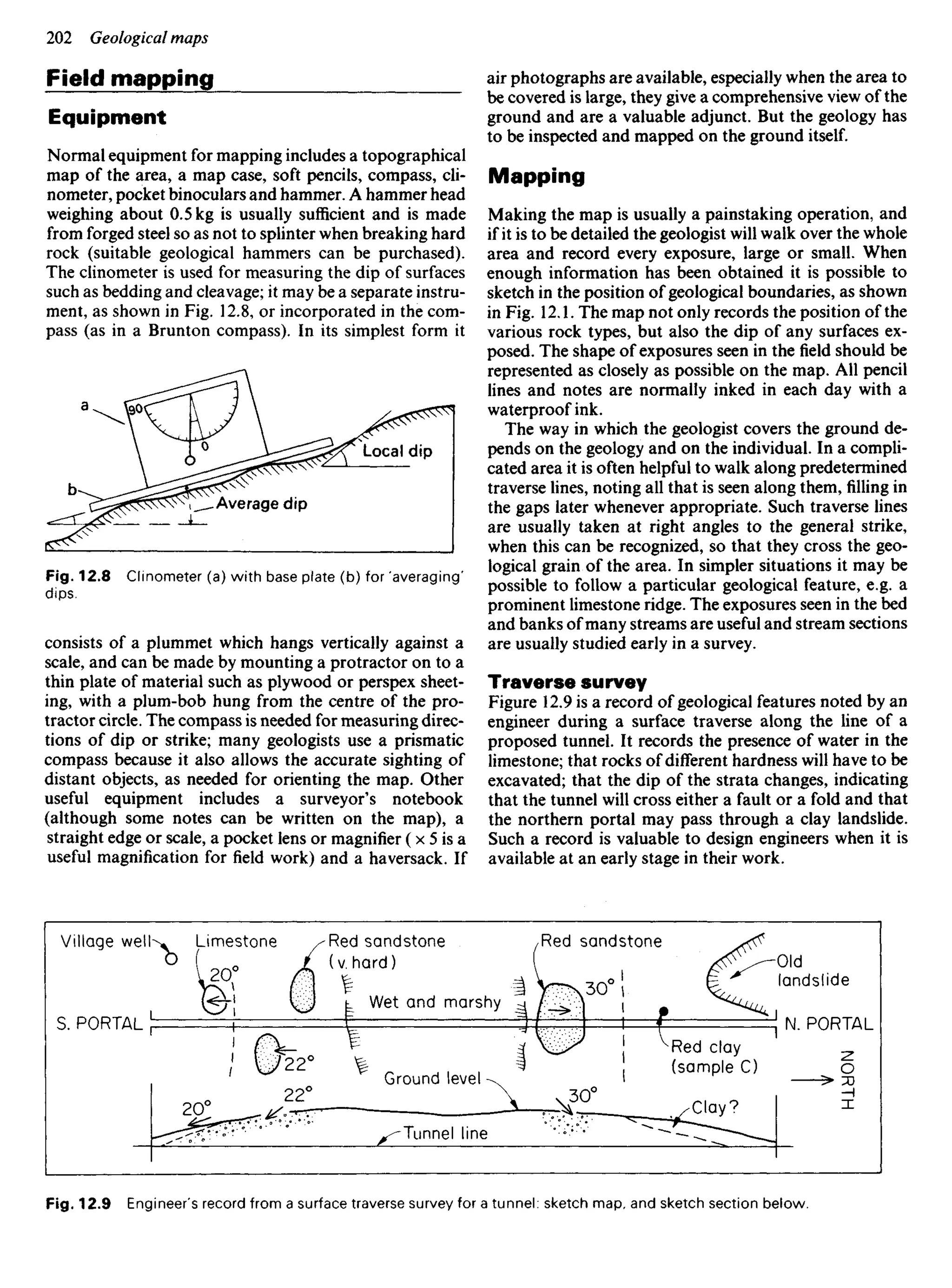
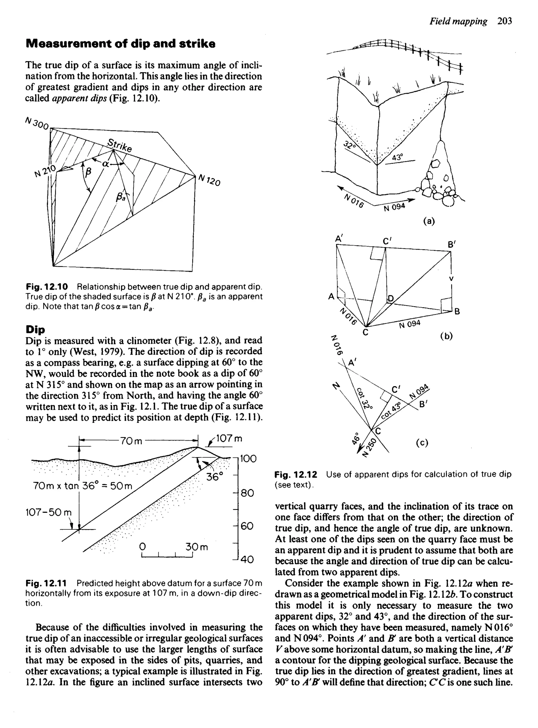
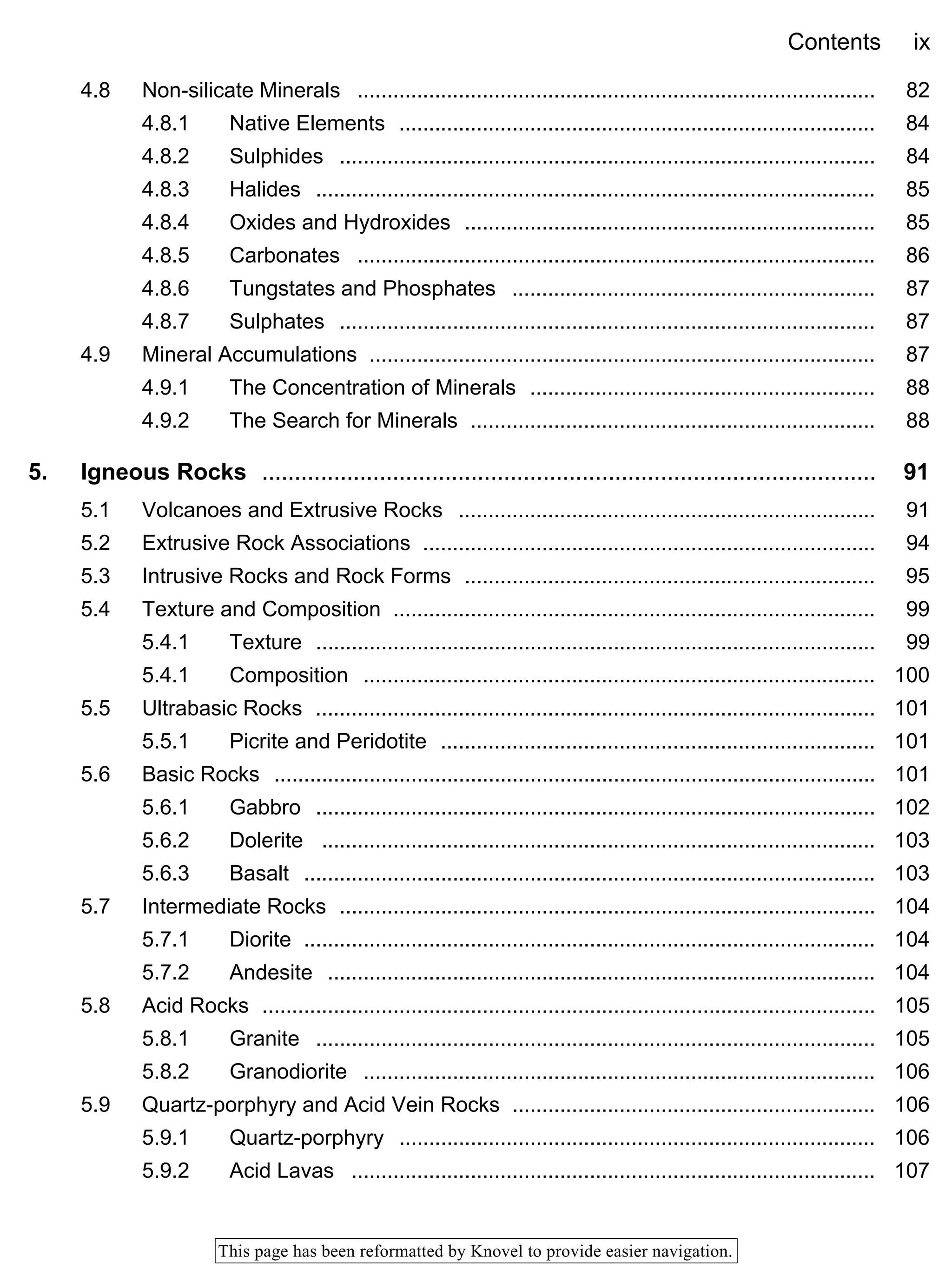
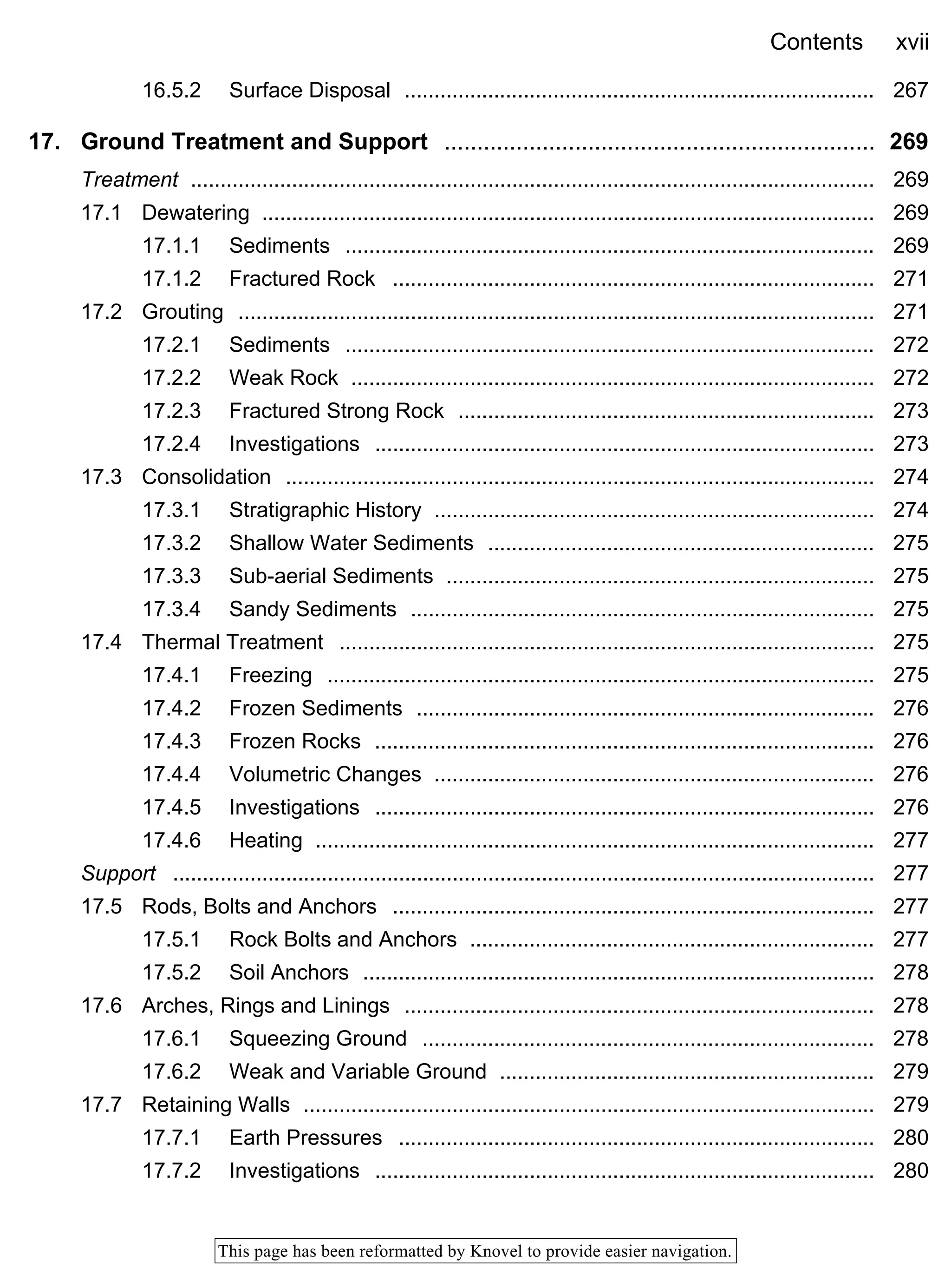
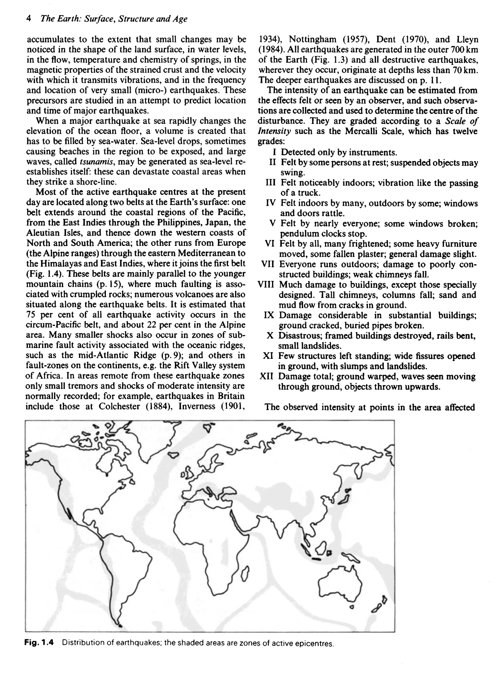
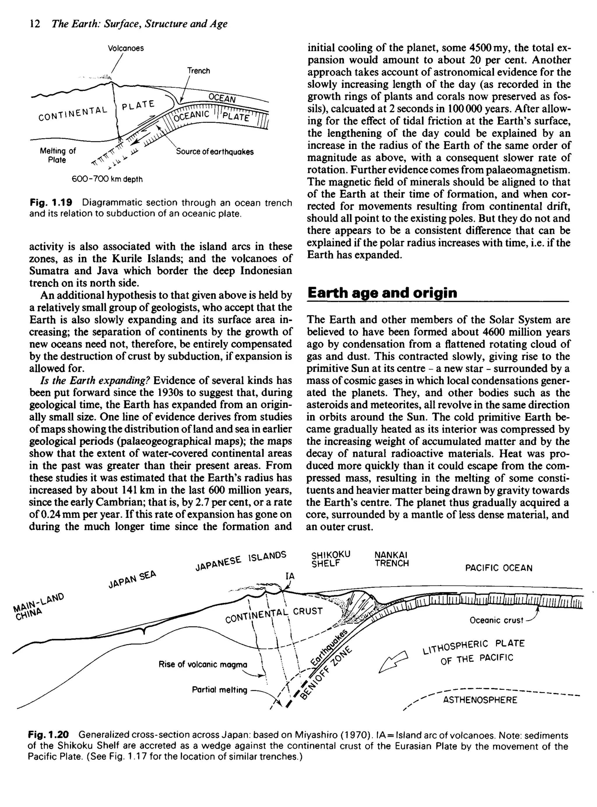
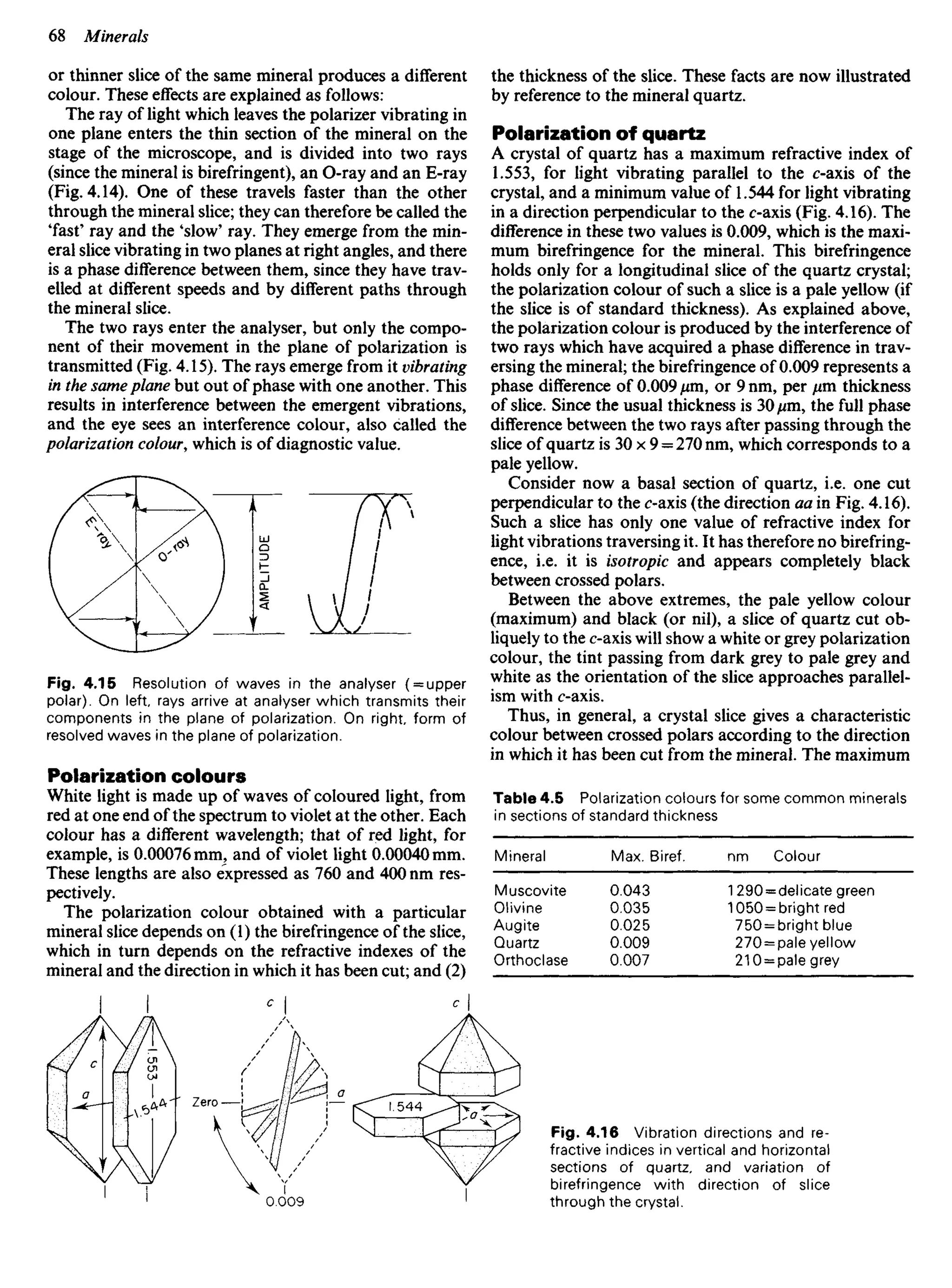
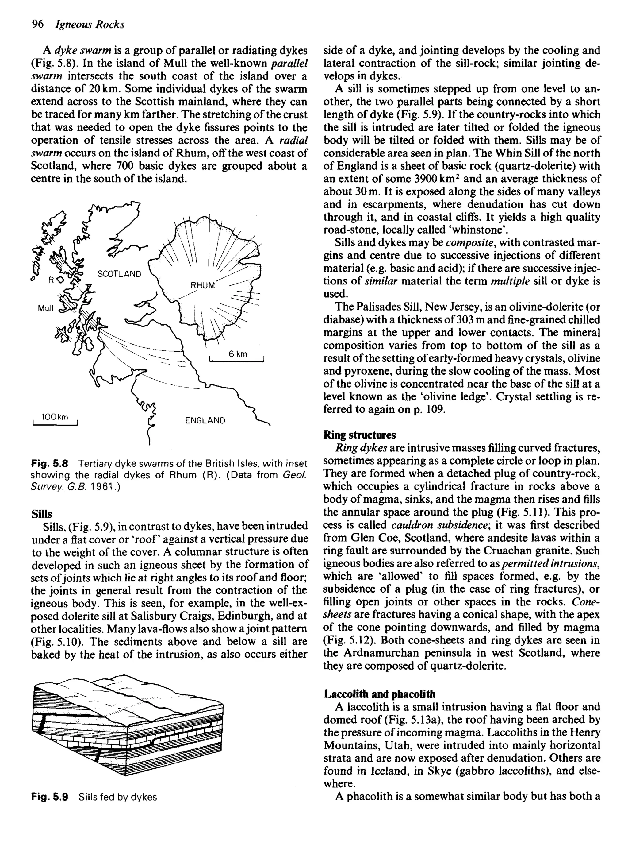
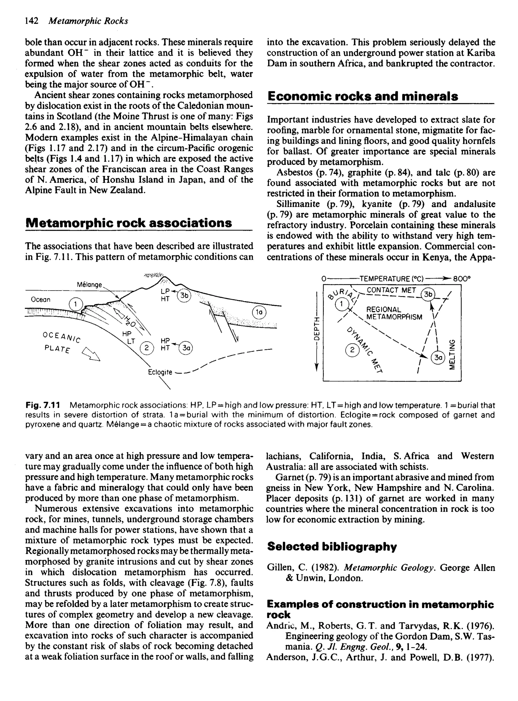
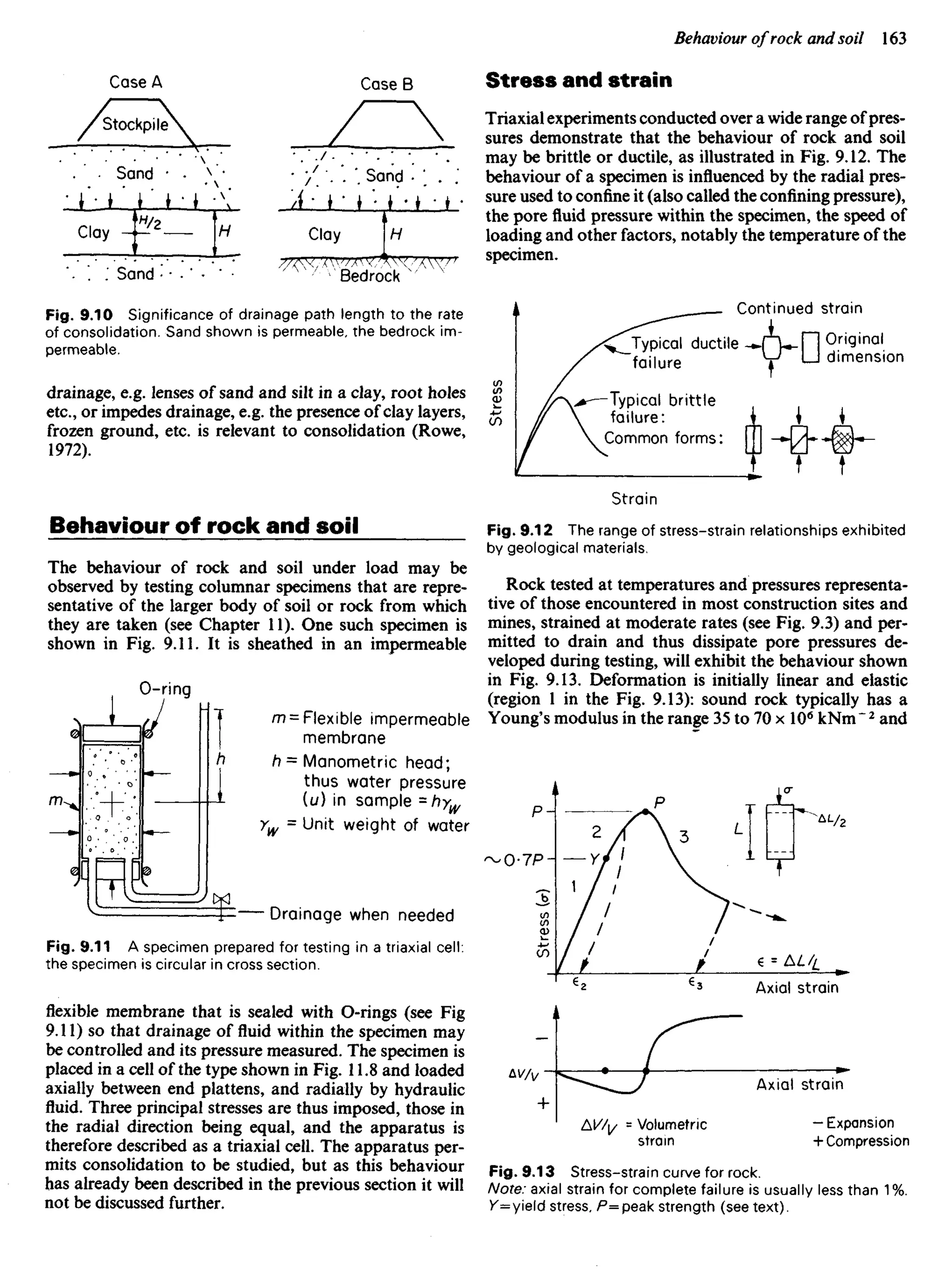
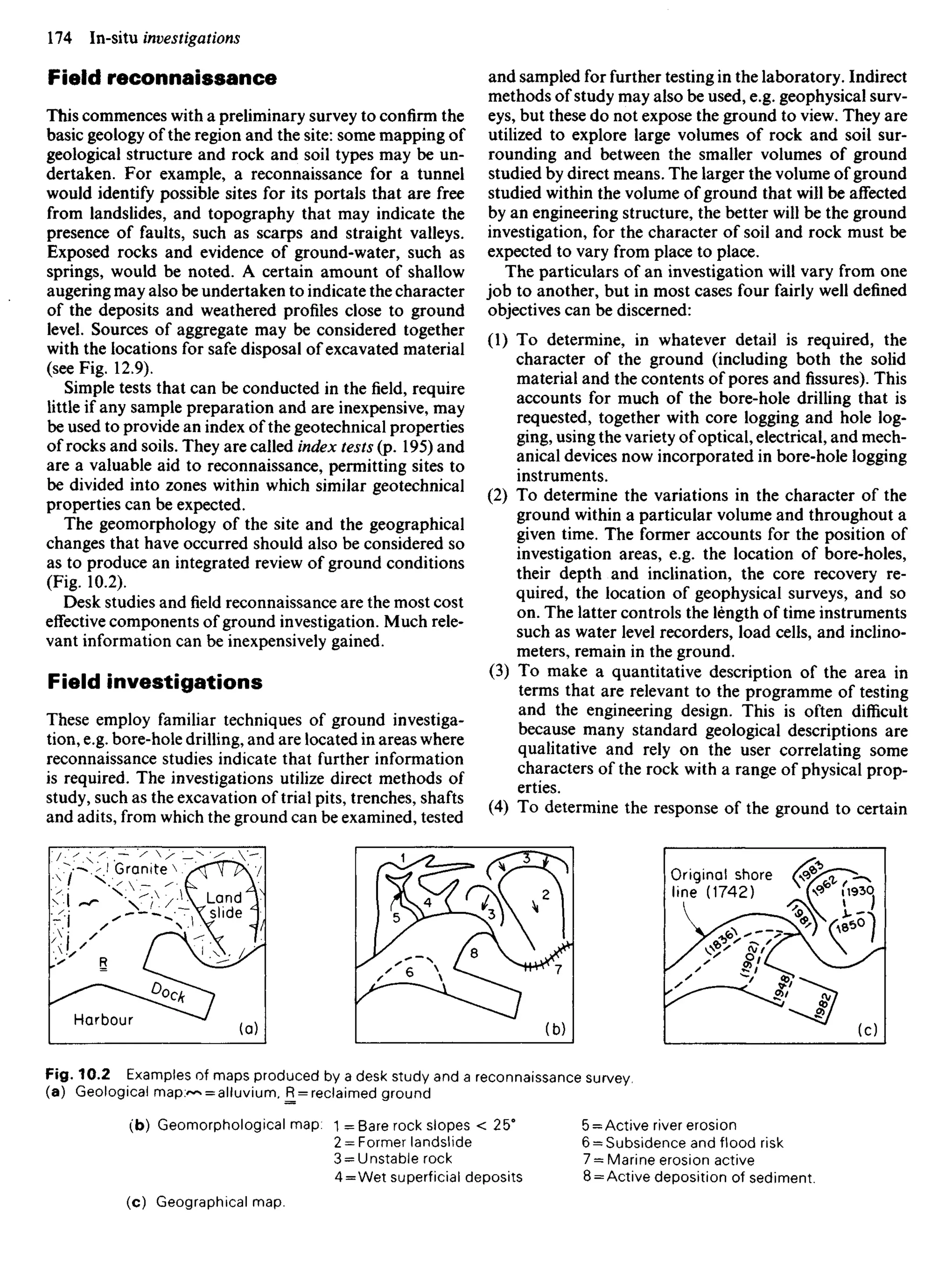
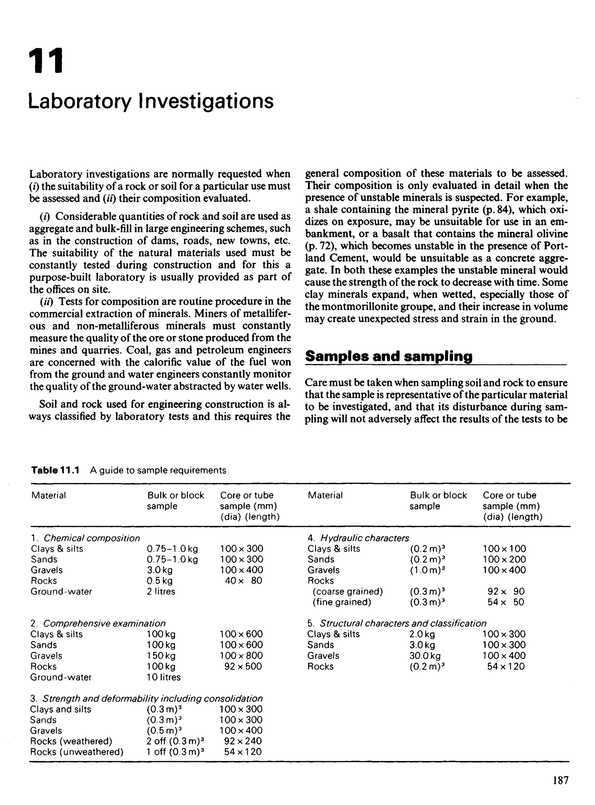
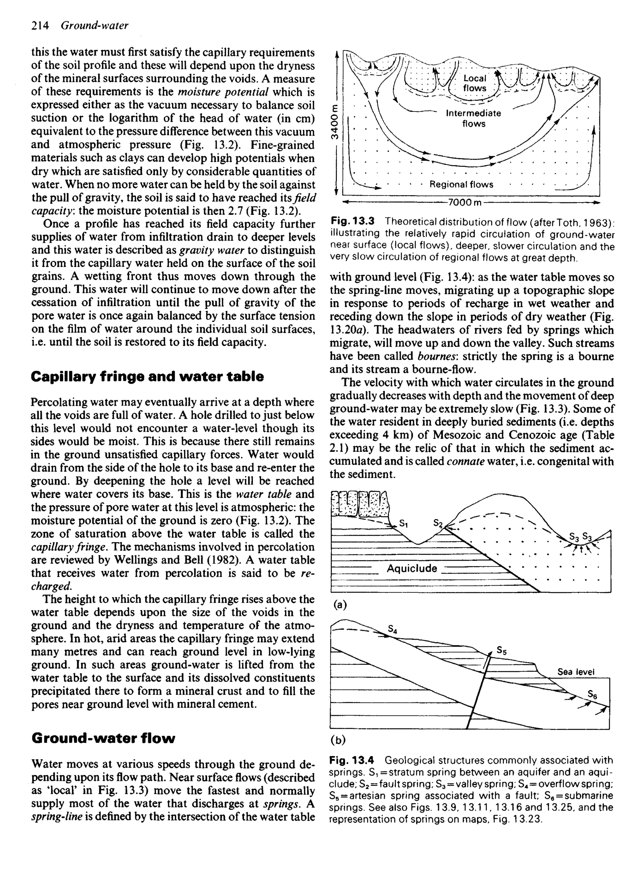
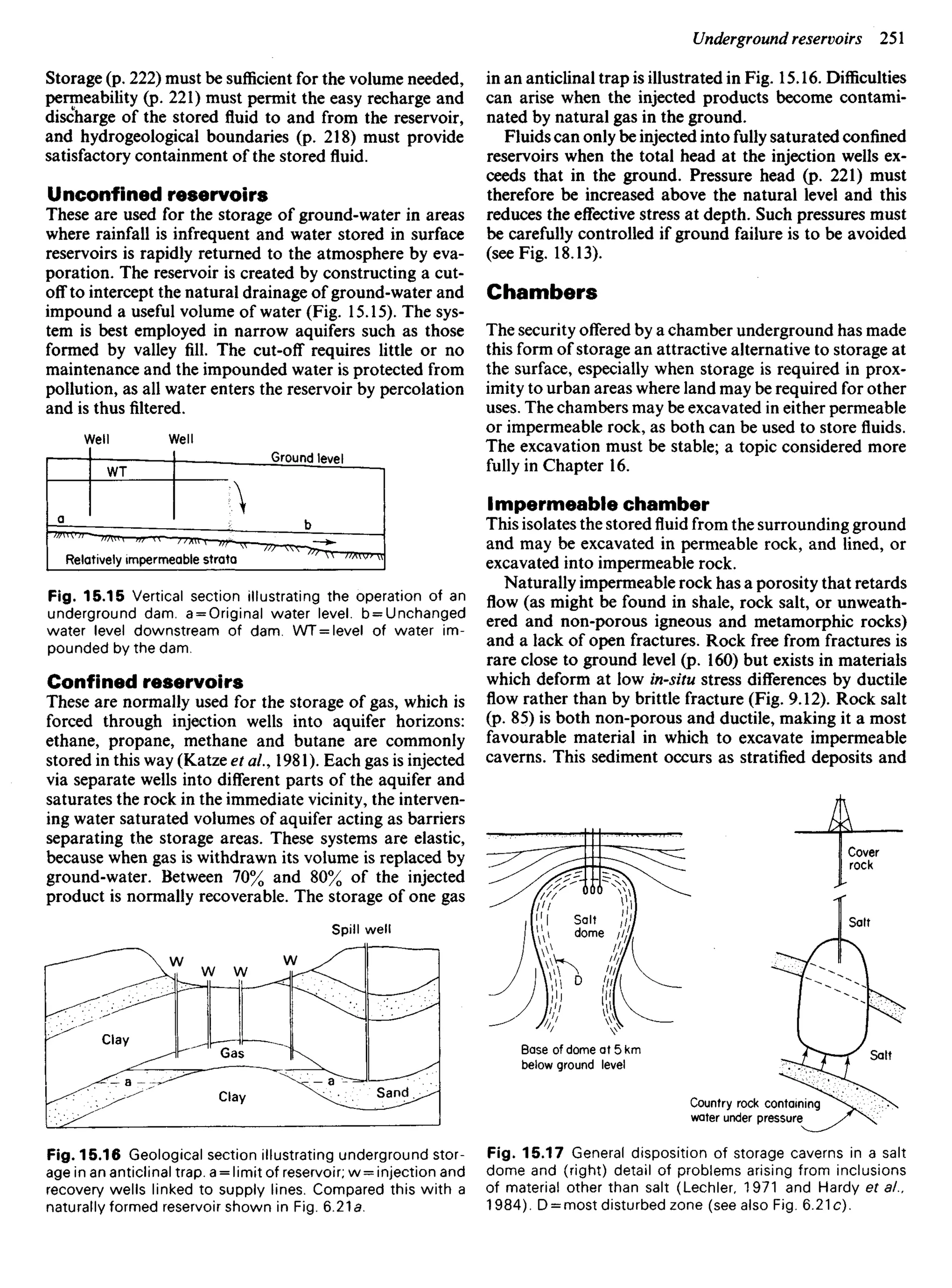
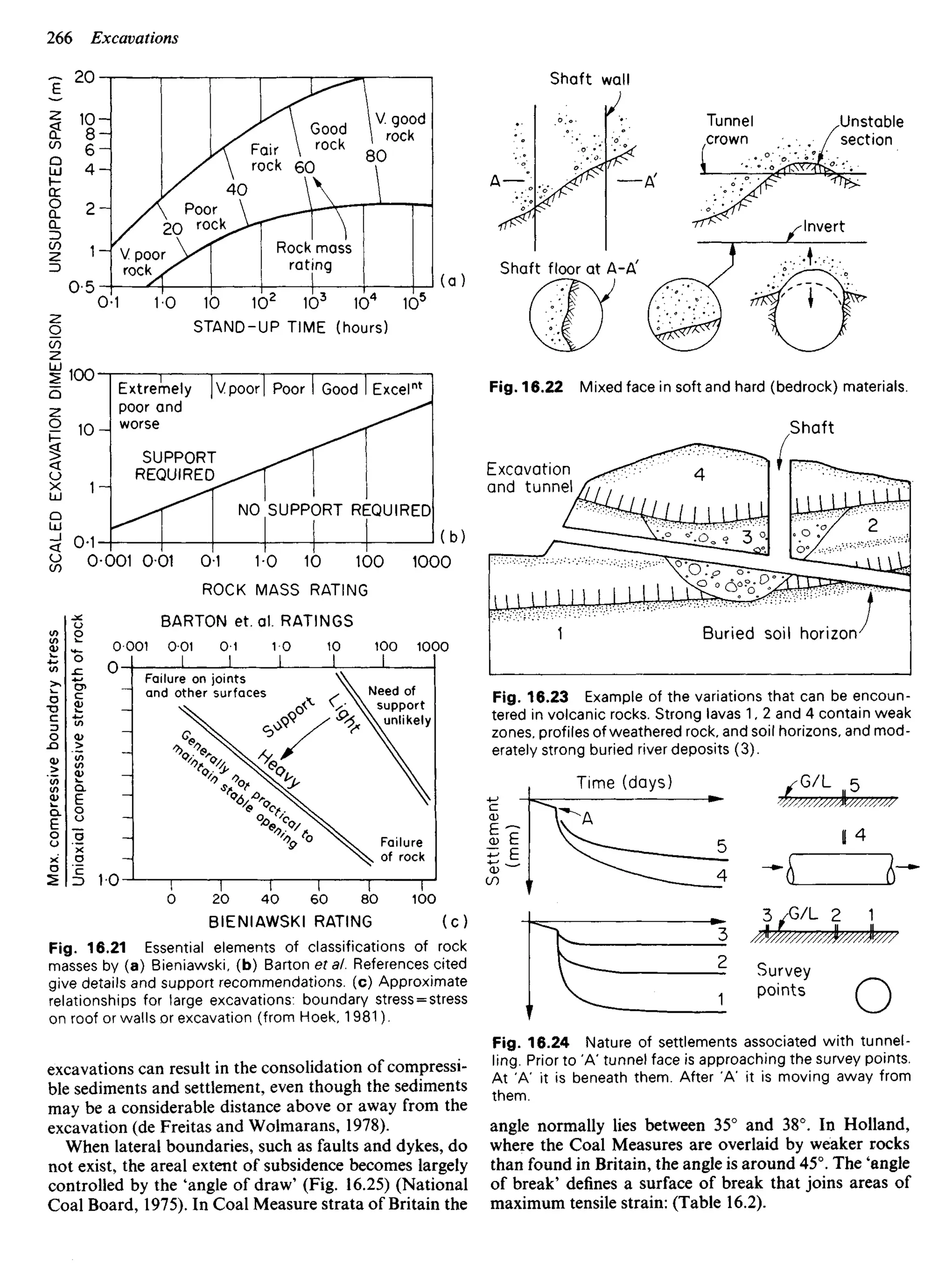
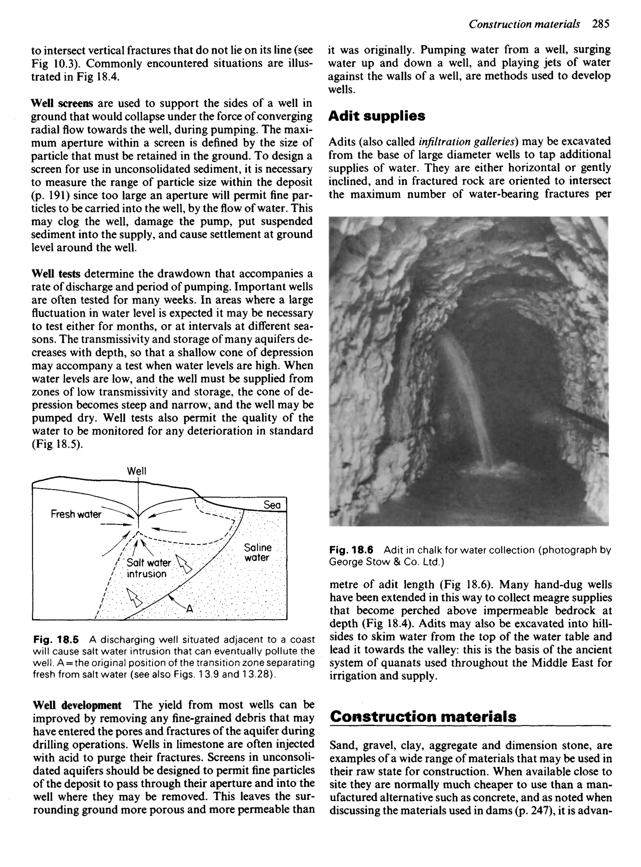
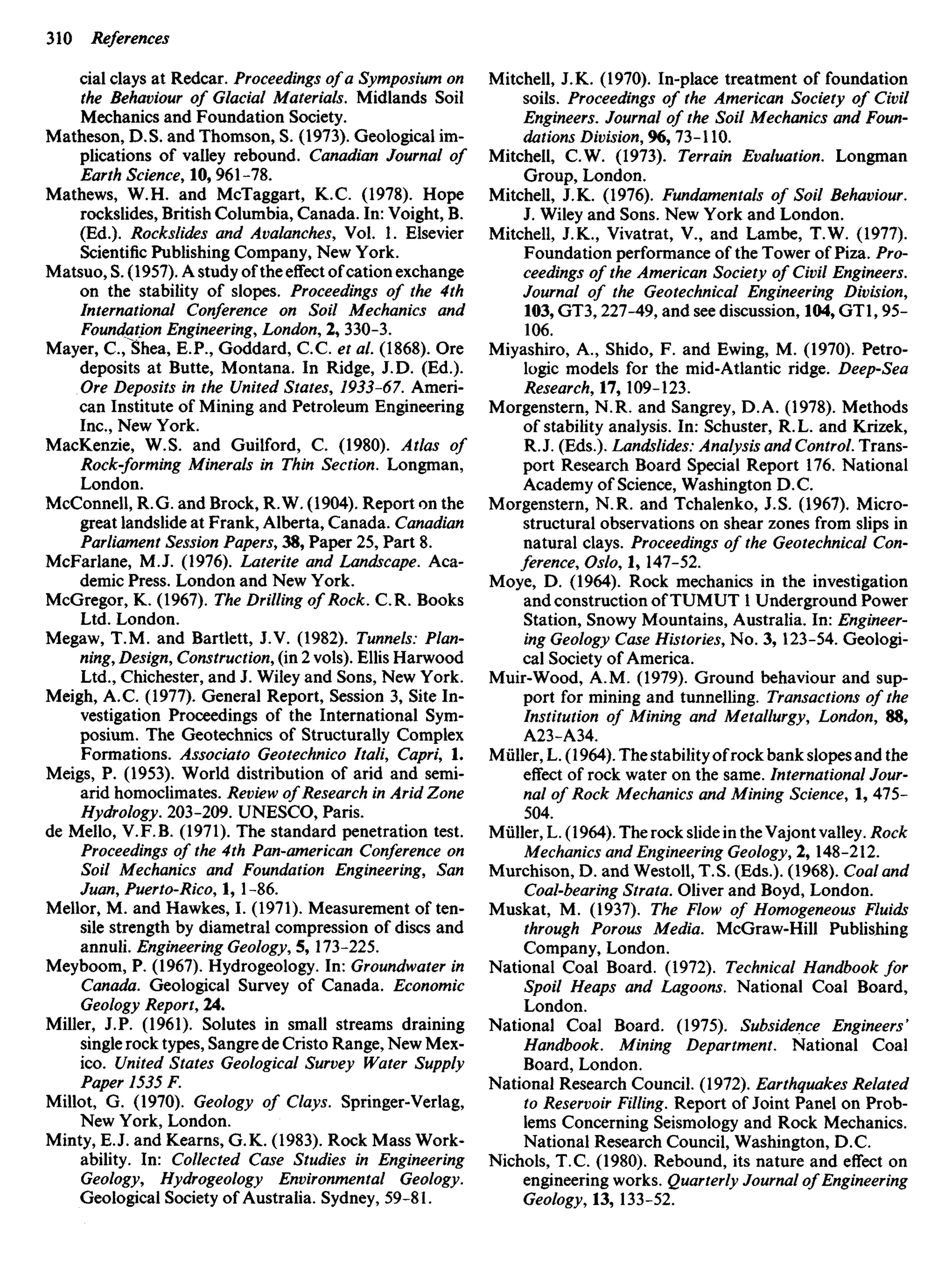
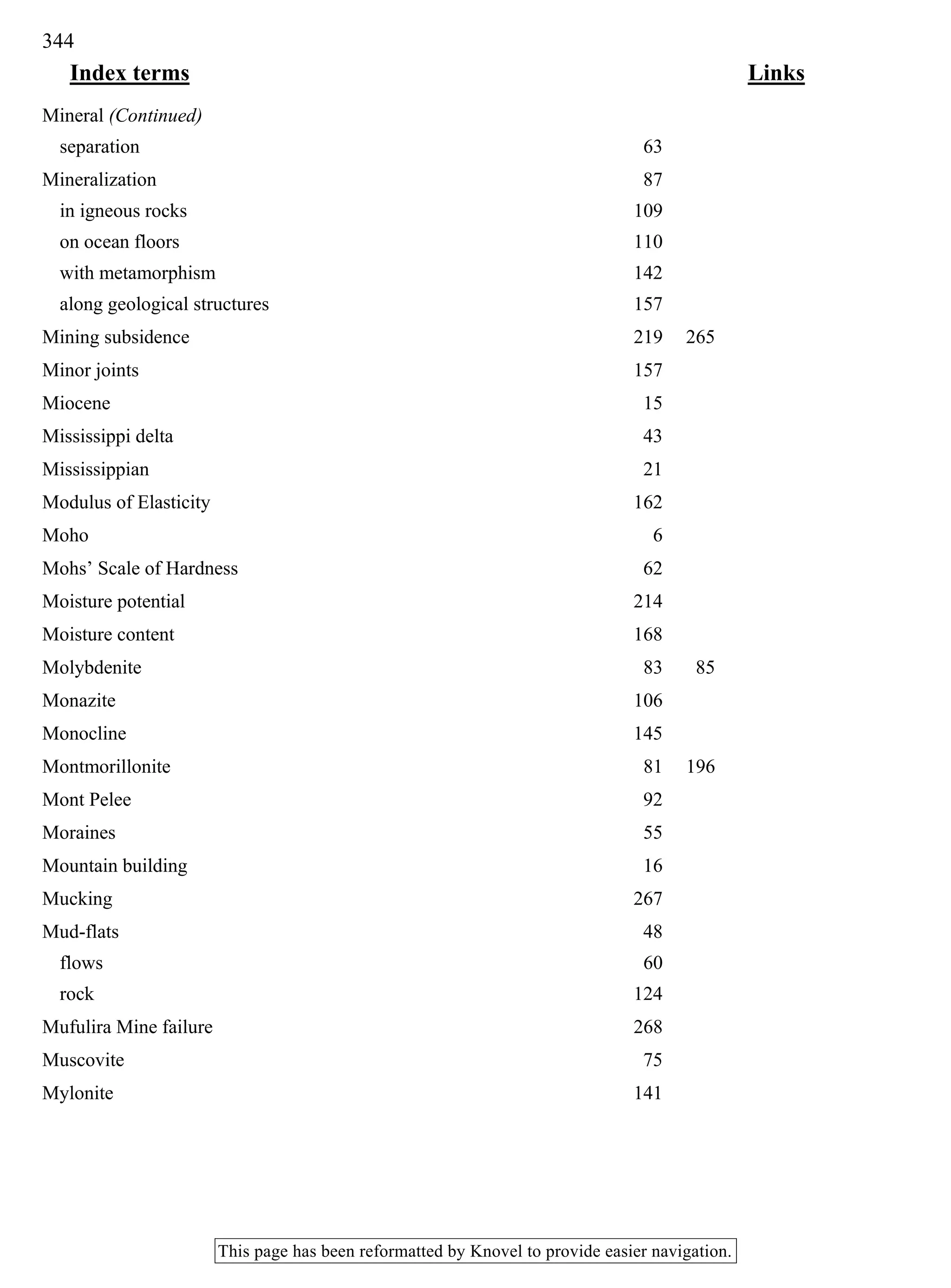
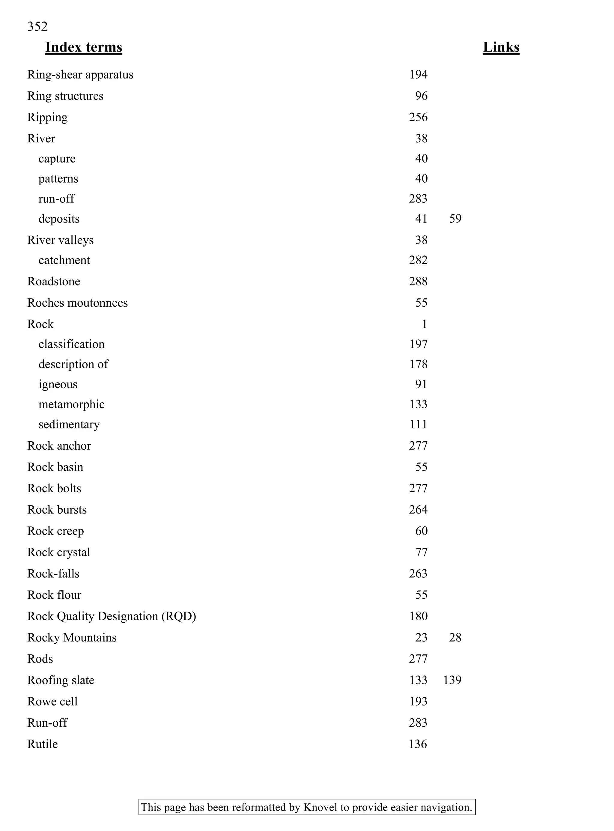
![The true dip, or inclination of CC to the horizontal, is
conveniently found by making a two-dimensional plan,
Fig. 12.12c. This diagram can be drawn directly from
field data using the following steps:
1 Draw a line to represent the direction of magnetic
North.
2 Select a point on this line to represent C.
3 From C draw two lines CA' and CE so that they are
correctly oriented to North. It is then necessary to
locate the points A and E on these lines.
[One of the commonest mistakes made with this construc-
tion is to draw the lines A'C and B'C on the wrong side of
the N-S line. The direction of faces A and B in Fig. 12.12a
could equally well have been recorded in the field as
N 196° and N 274° respectively. These directions, plotted
directly in plan, would have put the triangle AEC (to be
constructed) on the west side of the N-S line. The angle
of dip calculated would be the same as before, but the
direction of dip, if measured in the C-C direction, would
be in error by 180°. The construction triangle should
point in the same direction as the field exposure.]
4 From Fig. 12.126 it can be seen that AC=AAcOt 32°,
and BC=BE cot 43°. Because AA = BE= V, the ac-
tual length of V is immaterial to the construction and
can be conveniently taken as unity. The point A is
located a distance equal to cot 32° from C along the
line CA, and the point E a distance equal to cot 43°
along the line Ci?', to some suitable scale.
5 A line drawn at 90° to AE, i.e. CC, will lie in the
direction of true dip, and this direction can be
measured directly from the plan, i.e. N 250° in this
example.
The angle of true dip is C CD in Fig. 12.126. The length
DC = DC x cot CCD, because DC = V= 1, the equation
reduces to DC=cot CCD. Fig. 12.12c. Hence the angle
of true dip is that angle whose cotangent is equal to the
length CC, i.e. 46° in this example.
This graphical method is usually referred to as the
cotangent construction, and it can be used to interpret
the inclined surfaces exposed in trial pits, tenches, adits,
and similar excavations. Other methods are described by
Phillips (1971).
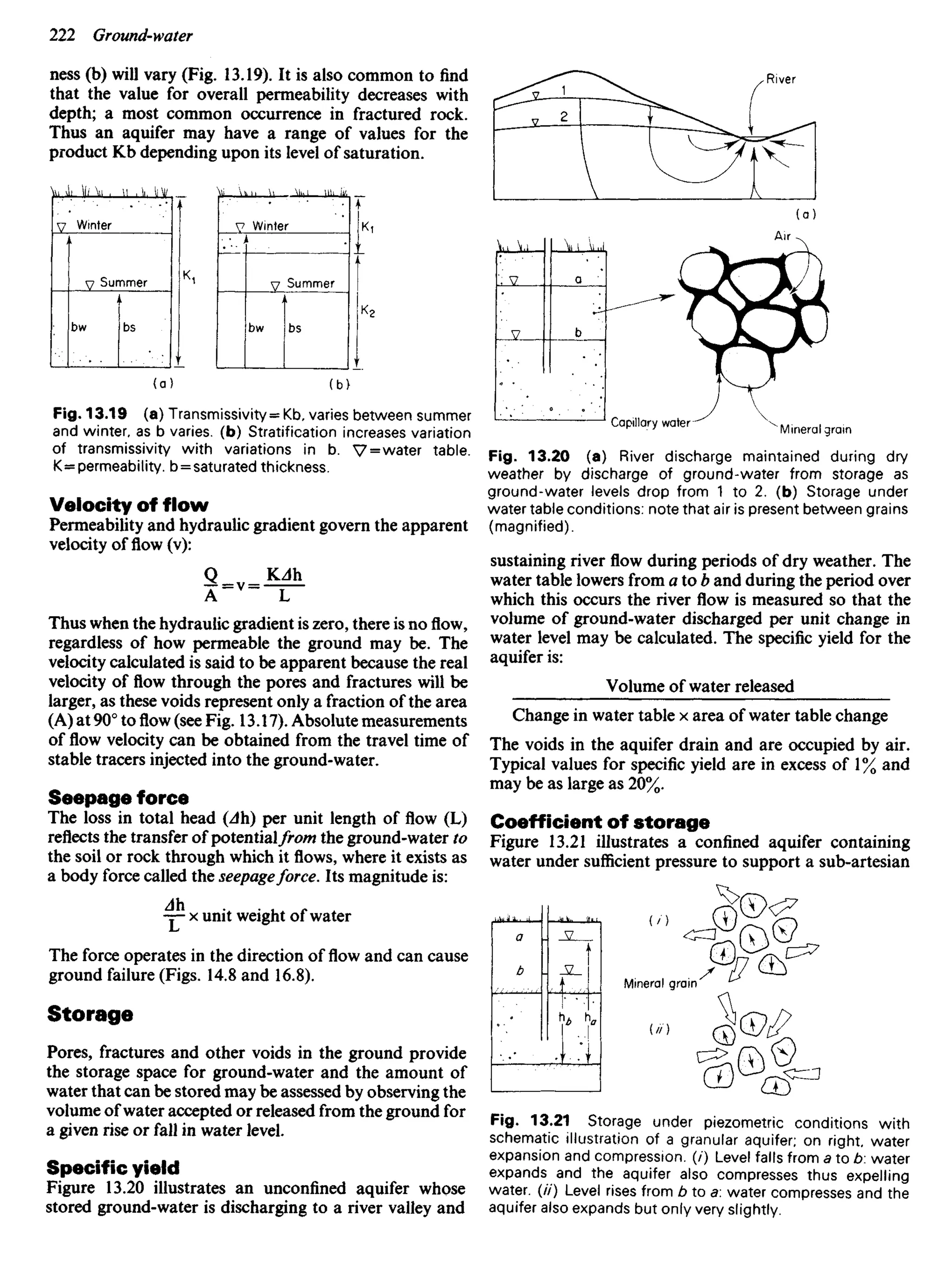
Strike
The strike of a surface is the direction of a horizontal line
drawn at 90° to the direction of true dip. The direction
N 120° (or N 300°) is the strike of the surface shown in
Fig. 12.10 as is the direction of the line AE in Fig. 12.126.
Because of its horizontality a line drawn in the direction
of strike is equivalent to an elevation contour for the
surface. Figure 12.13 illustrates how the strike directions
of a planar surface can be extended to produce strike lines
which are also contours for the surface and are called
structural contours. However, the majority of geological
surfaces are not planar and the unlimited extension of
strike lines away from the points at which dip and strike
are measured can result in incorrect predictions.
Fig. 12.13 Coastal exposure illustrating that strike lines at
chosen elevations can be extended to produce structural con-
tours for a surface.
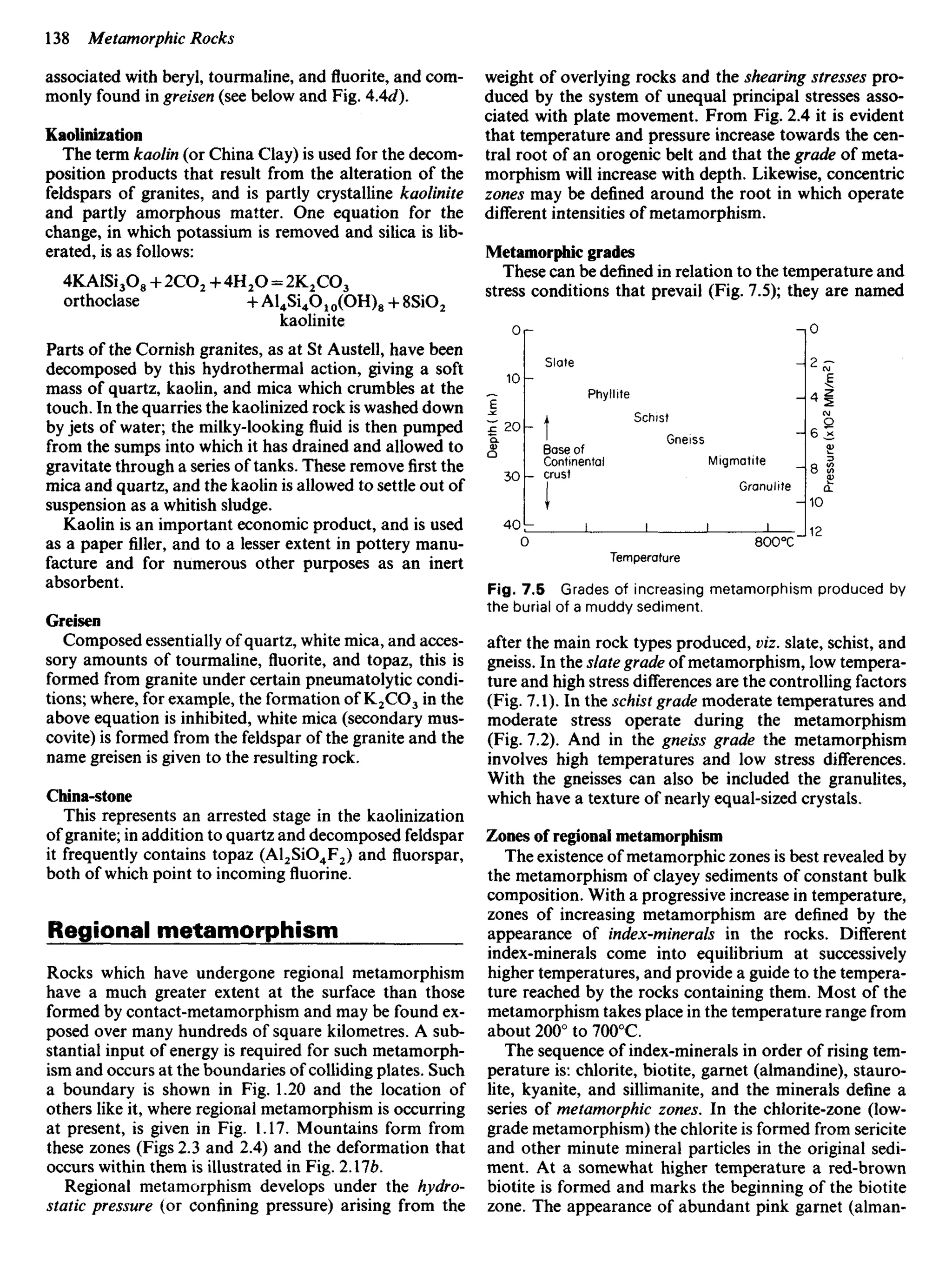
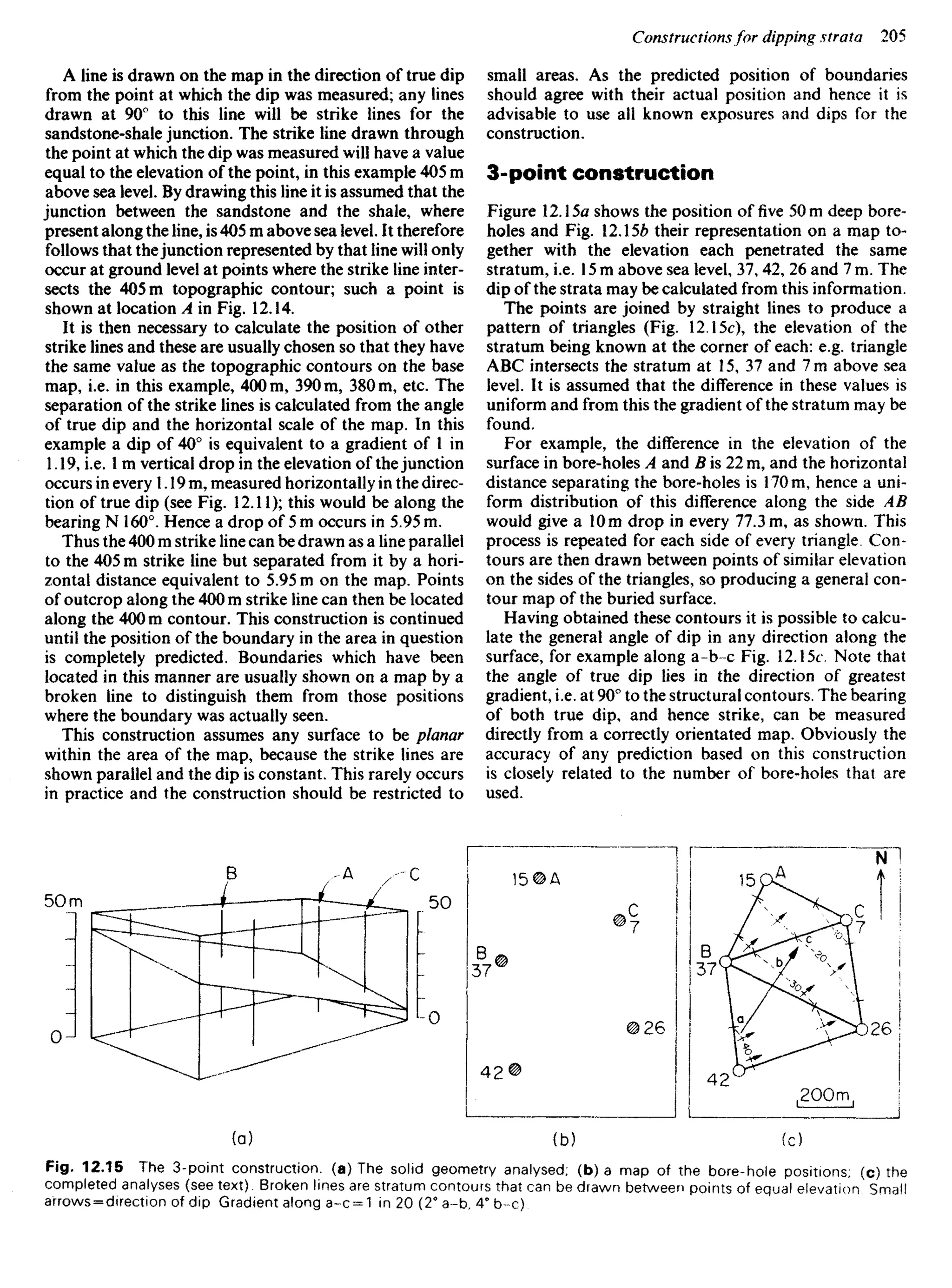
Constructions for dipping strata
The two constructions described here may be used to
predict the likely position of a concealed boundary.
Construction from outcrop
Figure 12.14 illustrates two small valleys between which
a hillside exposure reveals thejunction of sandstone (dot-
ted) with underlying shales. The dip of thisjunction at the
exposure is 40° at N 160°. In order to predict the approxi-
mate position of the junction in the area around the
exposure the following construction is used.
Fig. 12.14 Location of concealed boundary as defined
using stratum contours (see text).](https://image.slidesharecdn.com/ageologyforengineersseventhedition-240123054612-a0c16209/75/A_Geology_for_Engineers_Seventh_Edition-pdf-188-2048.jpg)


![18
Development and Redevelopment
The development of a community may be influenced by
many geological phenomena, for example, earthquakes
(Chapter 1), weathering and erosion (Chapter 3), volcan-
oes (Chapter 5), landslides and avalanches of rock and
soil (Chapter 14). To these obstacles may also be added
the problems of engineering with the materials and land-
scape created by geological processes, for example, the
difficulty of creating reservoirs (Chapter 15), and of ex-
cavating routes for communications (Chapter 14 and 16).
These, and other examples, are mentioned in previous
Chapters, as indicated.
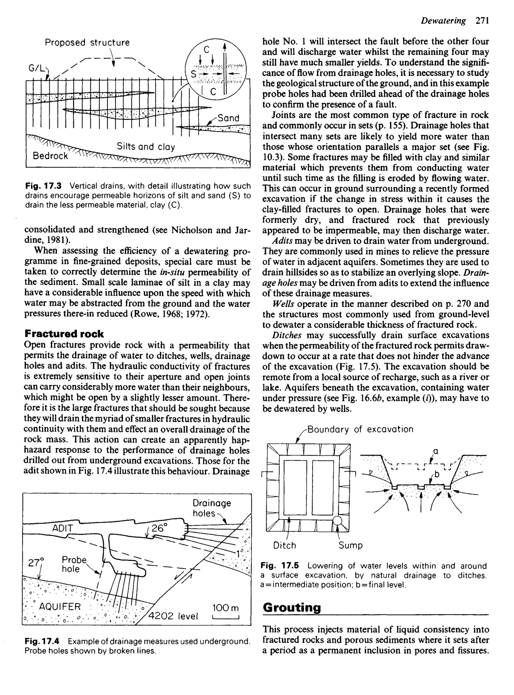
In this Chapter we wish to describe those geological
factors that affect (/) the provision of an adequate supply
of water from underground sources; (//) the suitability of
minerals, sediments and rocks as materials for the con-
struction of engineering structures; (Hi) the design of
foundations that will safely transfer to the ground the
load of the structure they must carry, and (iv) the safe and
controlled disposal of waste, on land.
Water supplies
Most ground-water supplies tap localflowsof circulating
meteoric water (p. 213 and Fig. 13.3) that exist within the
catchment over which rain has fallen.
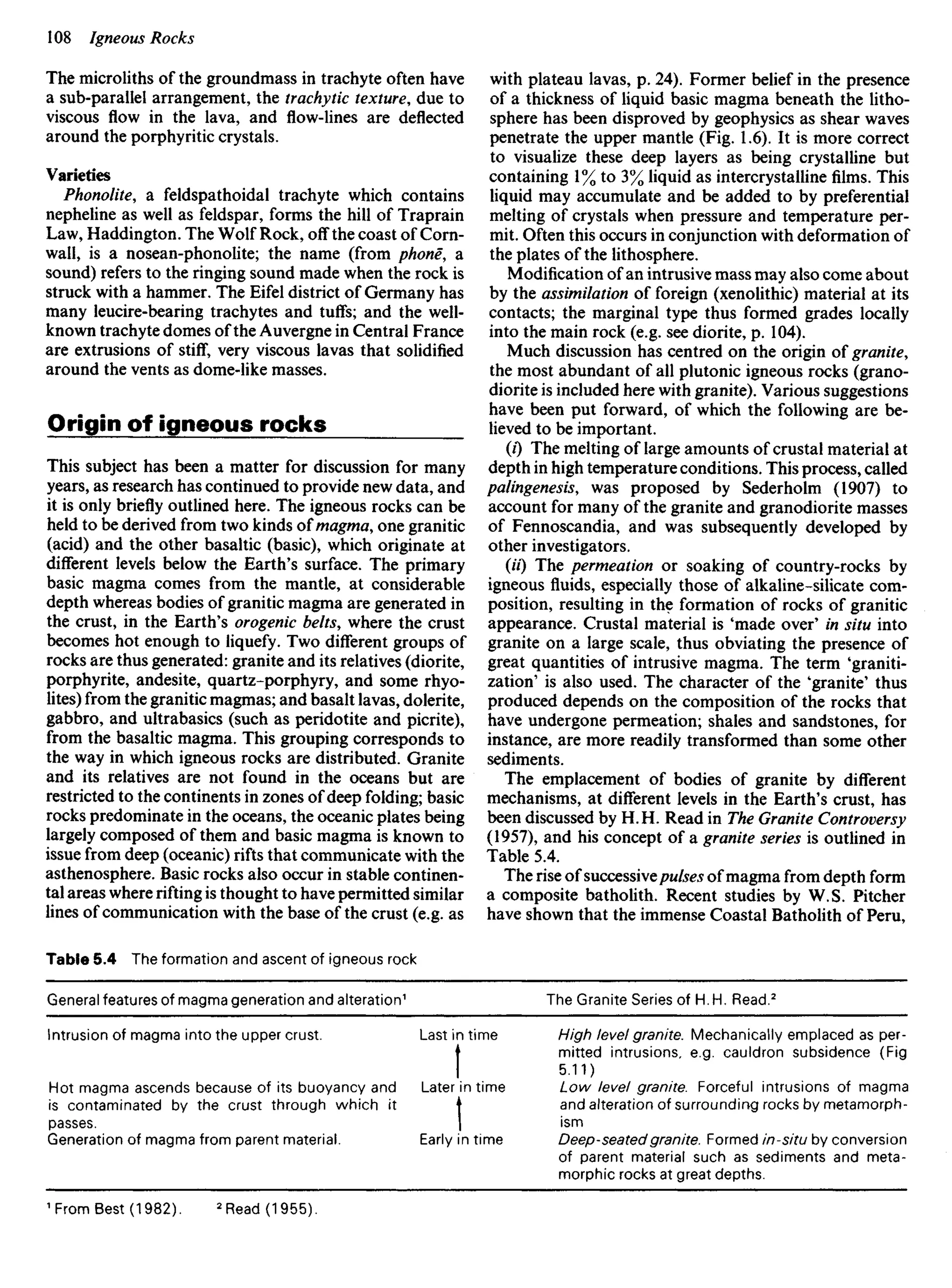
Catchments
Two types of catchment must be recognized, namely sur-
face and underground.
Surface catchments are bounded by the highest ground
separating neighbouring drainage systems. This high
ground is called the surface-divide or watershed. Rain
falling on an impermeable catchment will drain over its
surface to the river within the catchment.
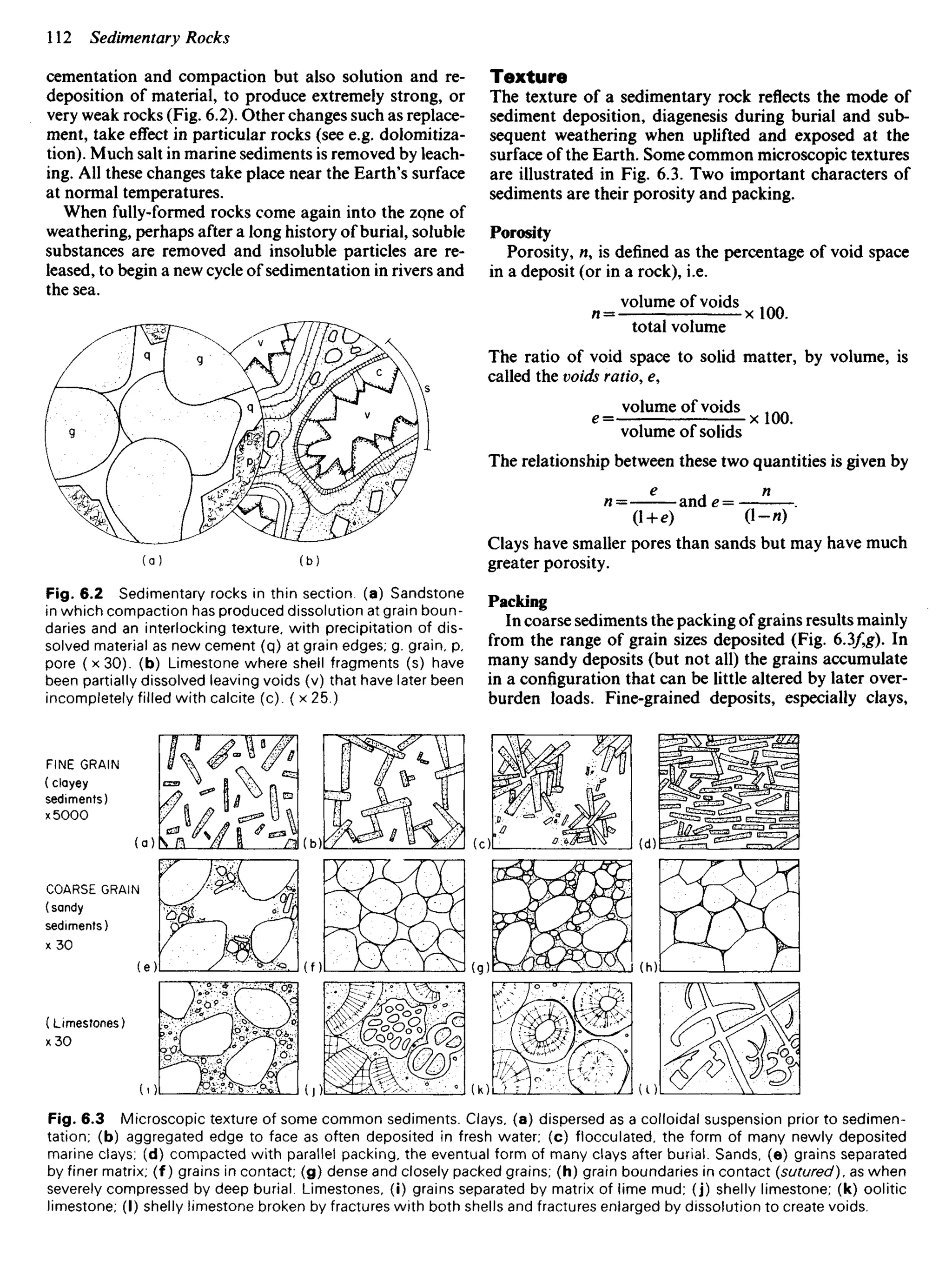
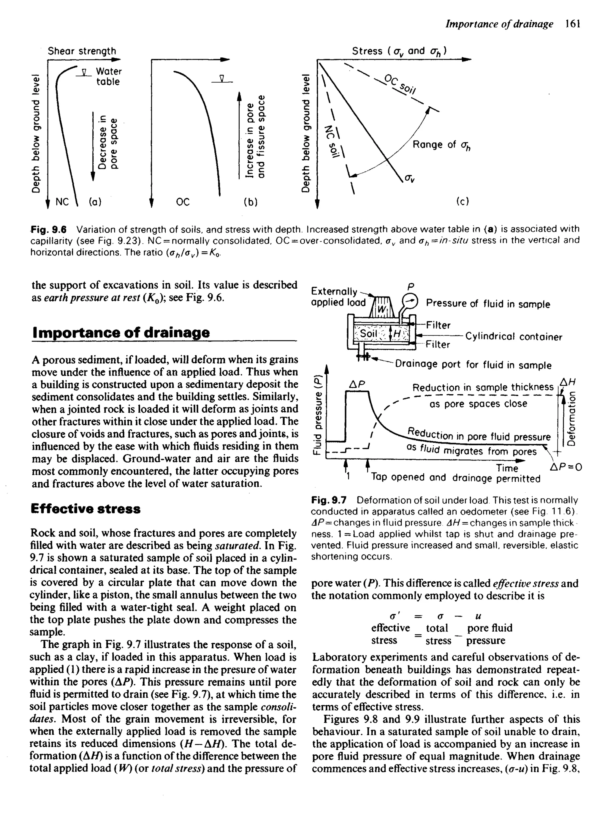
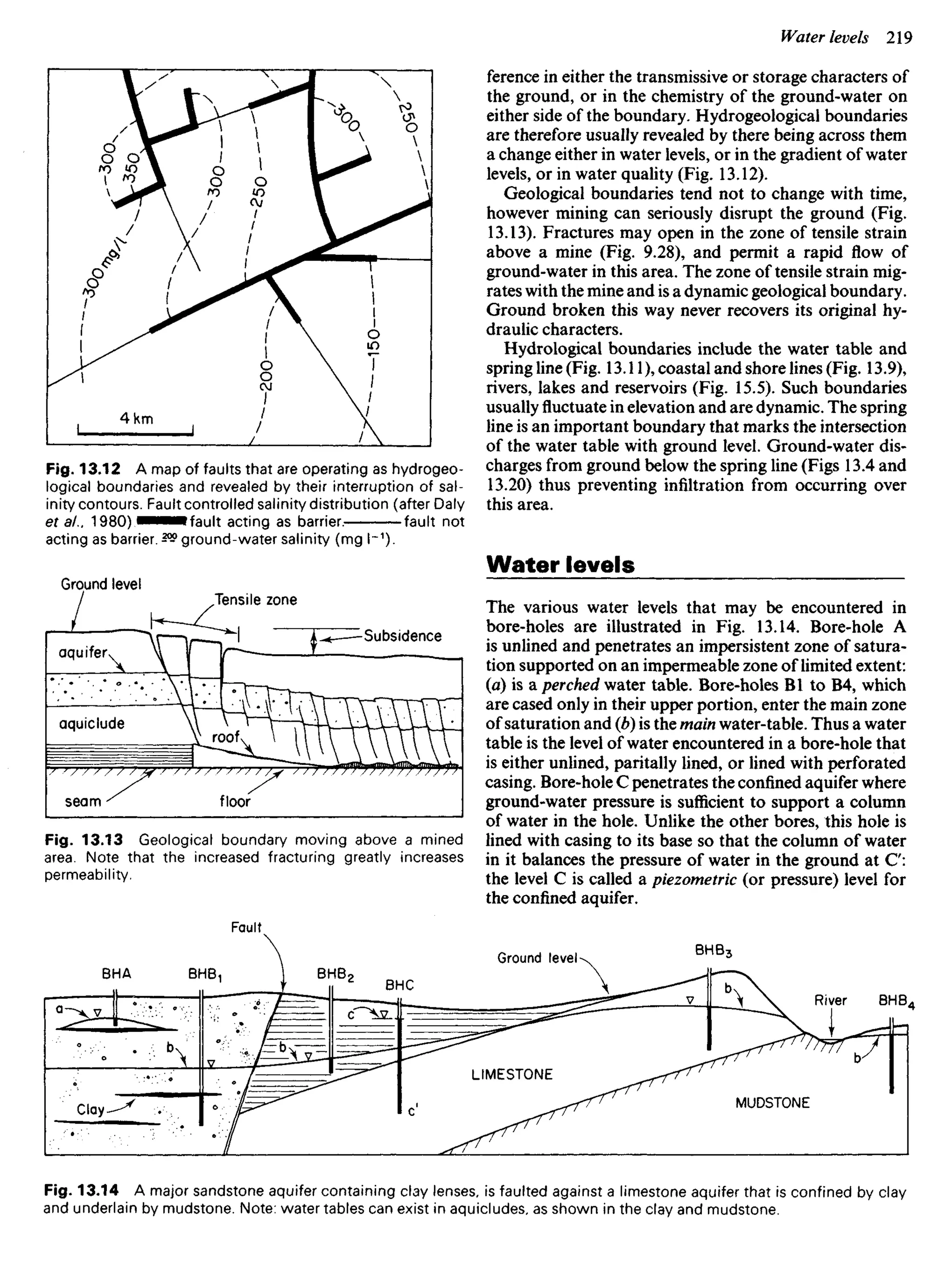
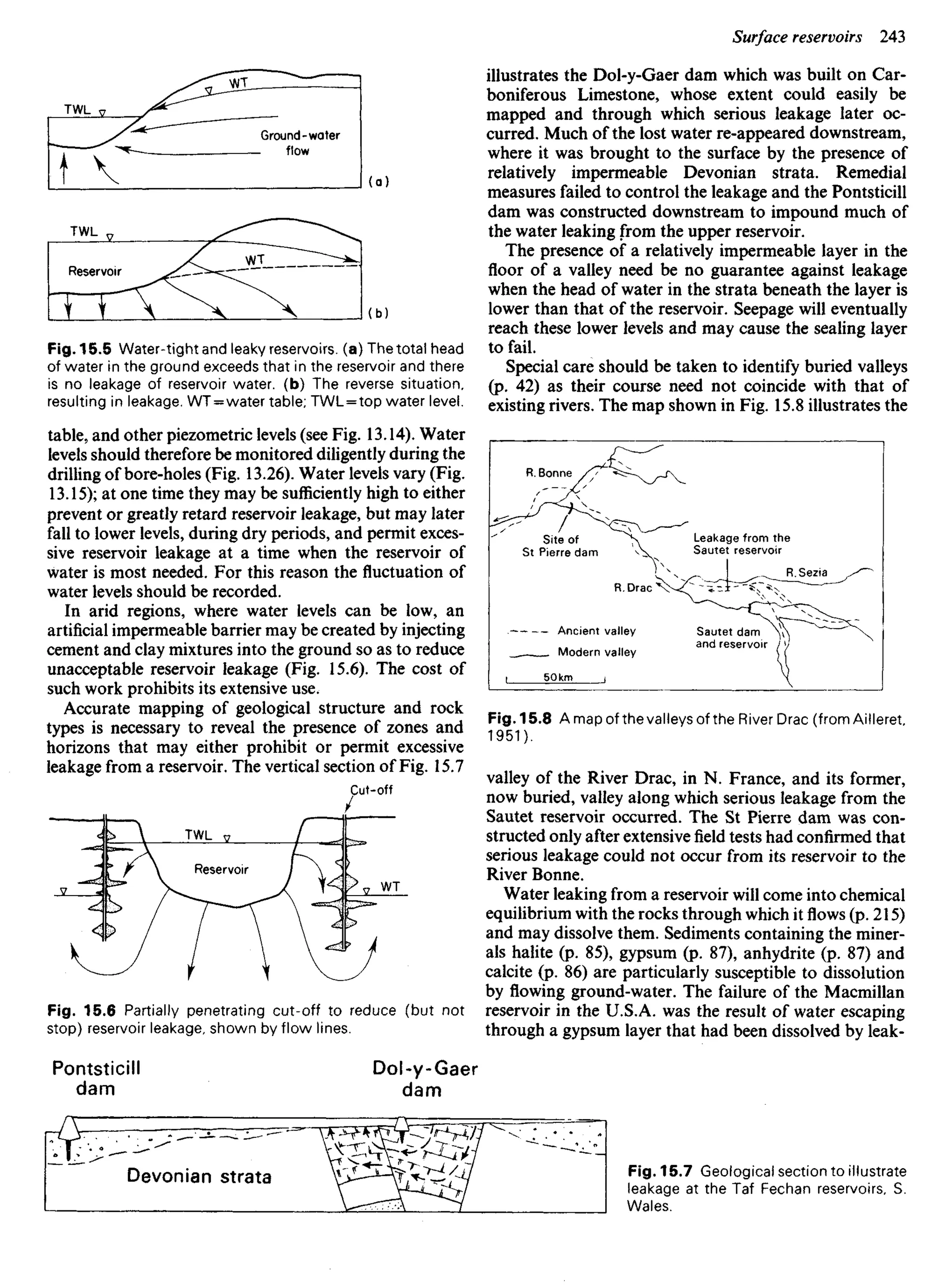
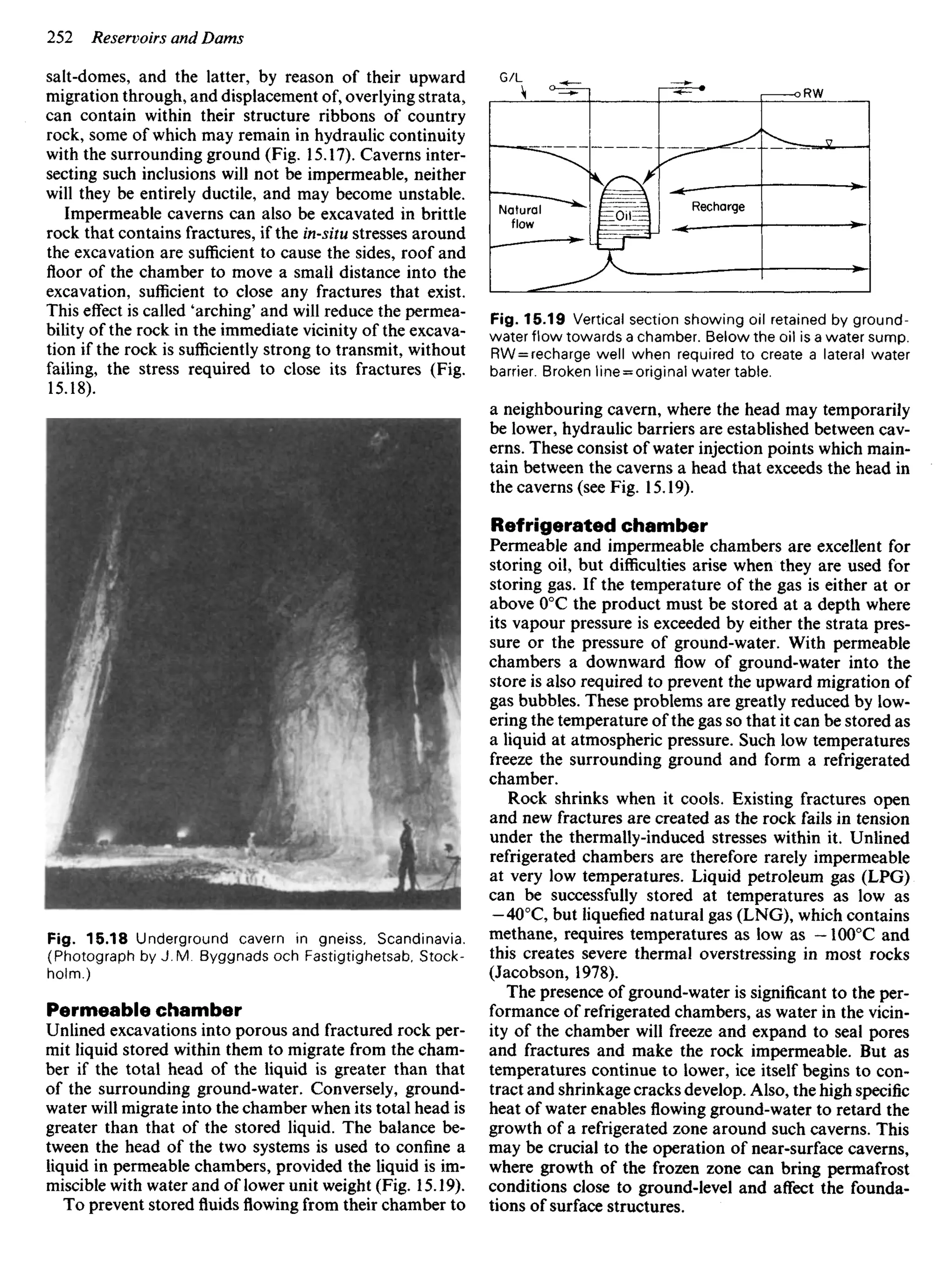
Underground catchments are defined by water levels, not
ground levels, and are bounded by a line that joins the
highest water levels beneath a surface catchment. This
line is called the ground-water divide. Often, the boundary
of the underground catchment lies almost vertically be-
neath that of the surface catchment, and rain percolating
to the water table will be carried by ground-water flow
towards the river draining the surface catchment (see Figs
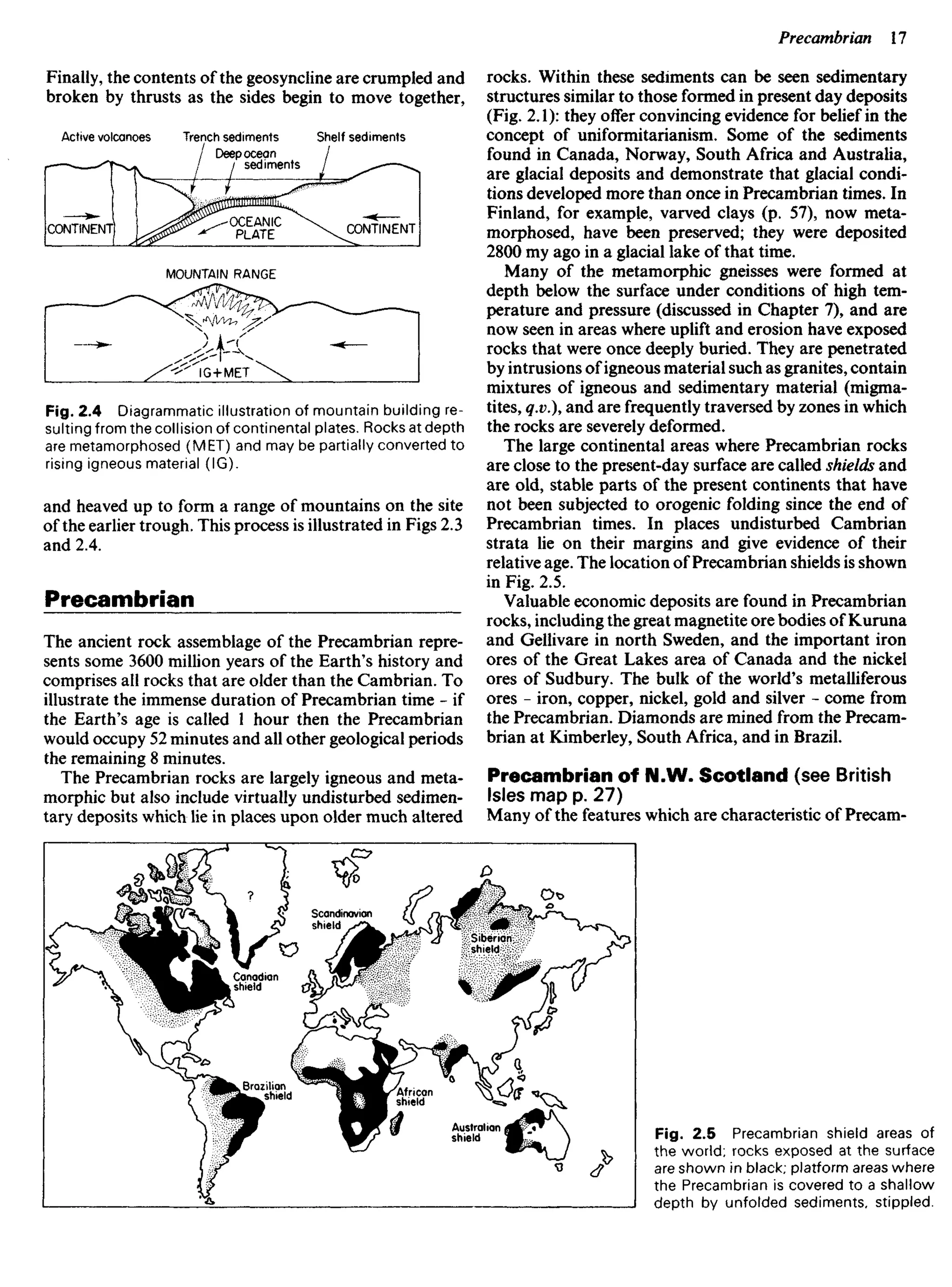
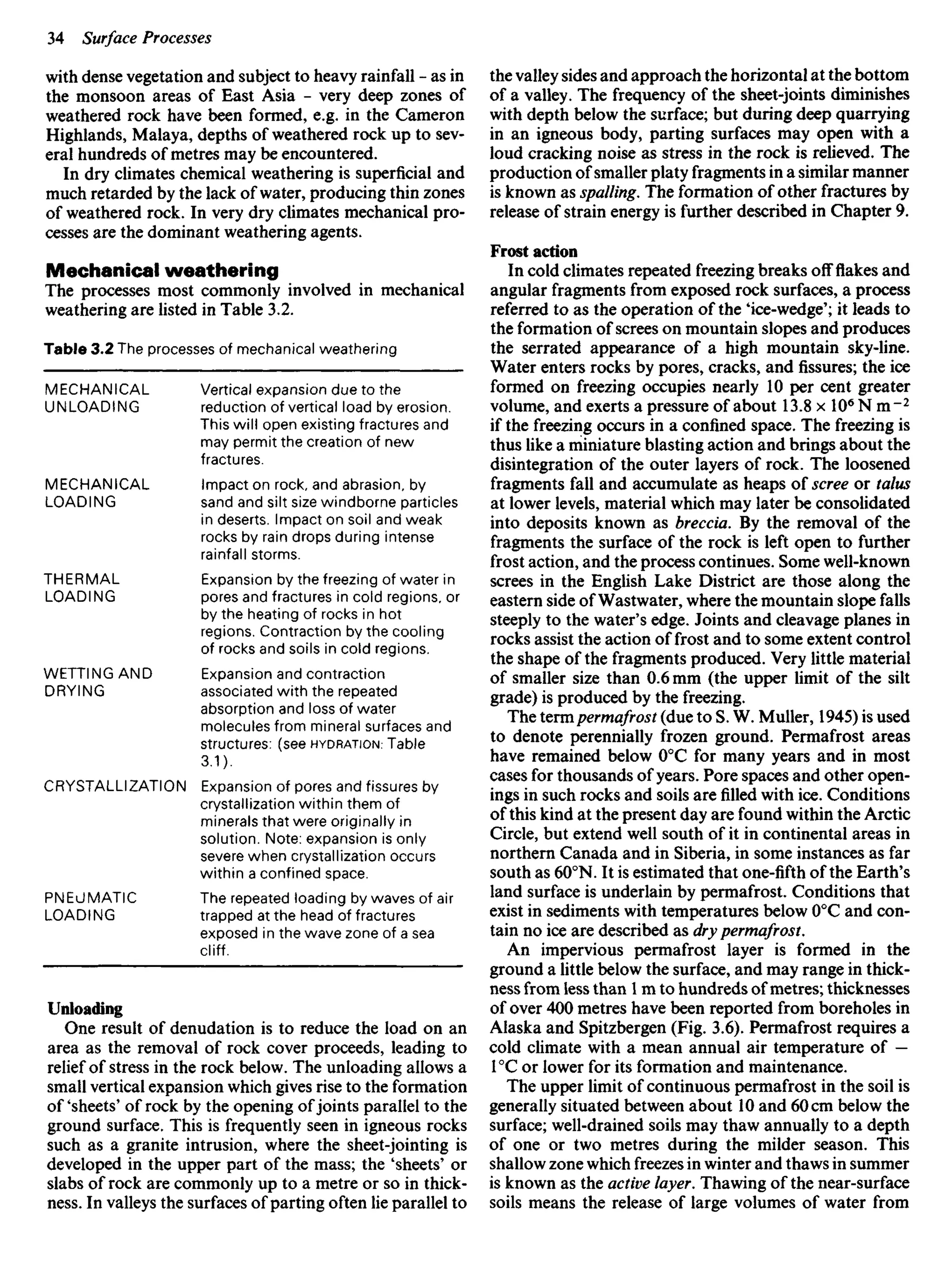
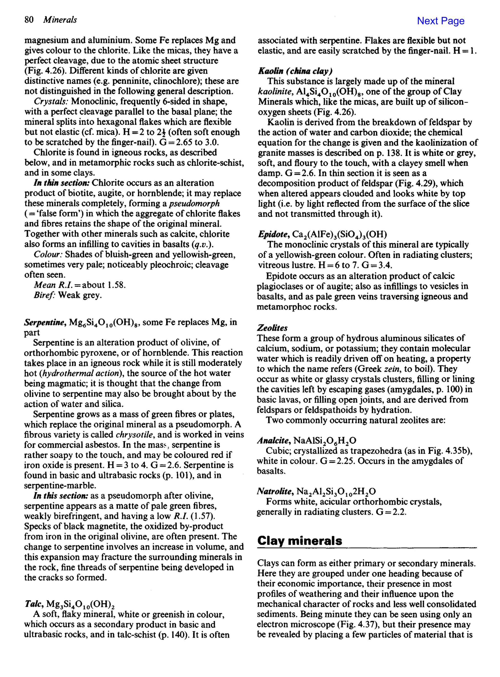
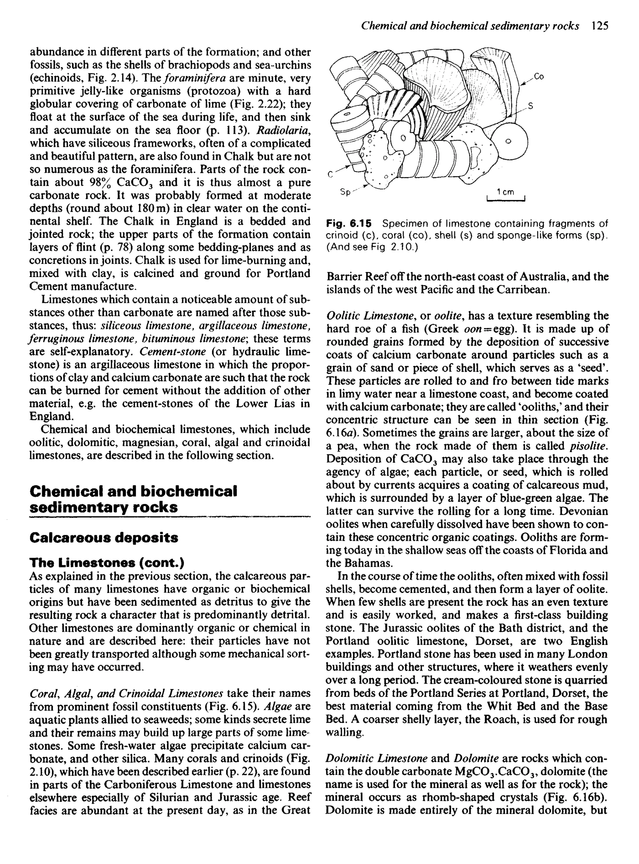
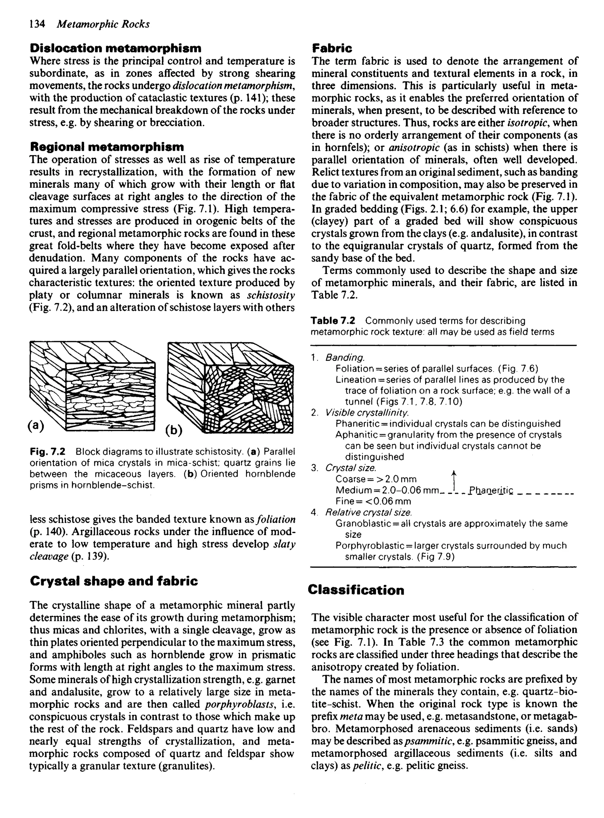
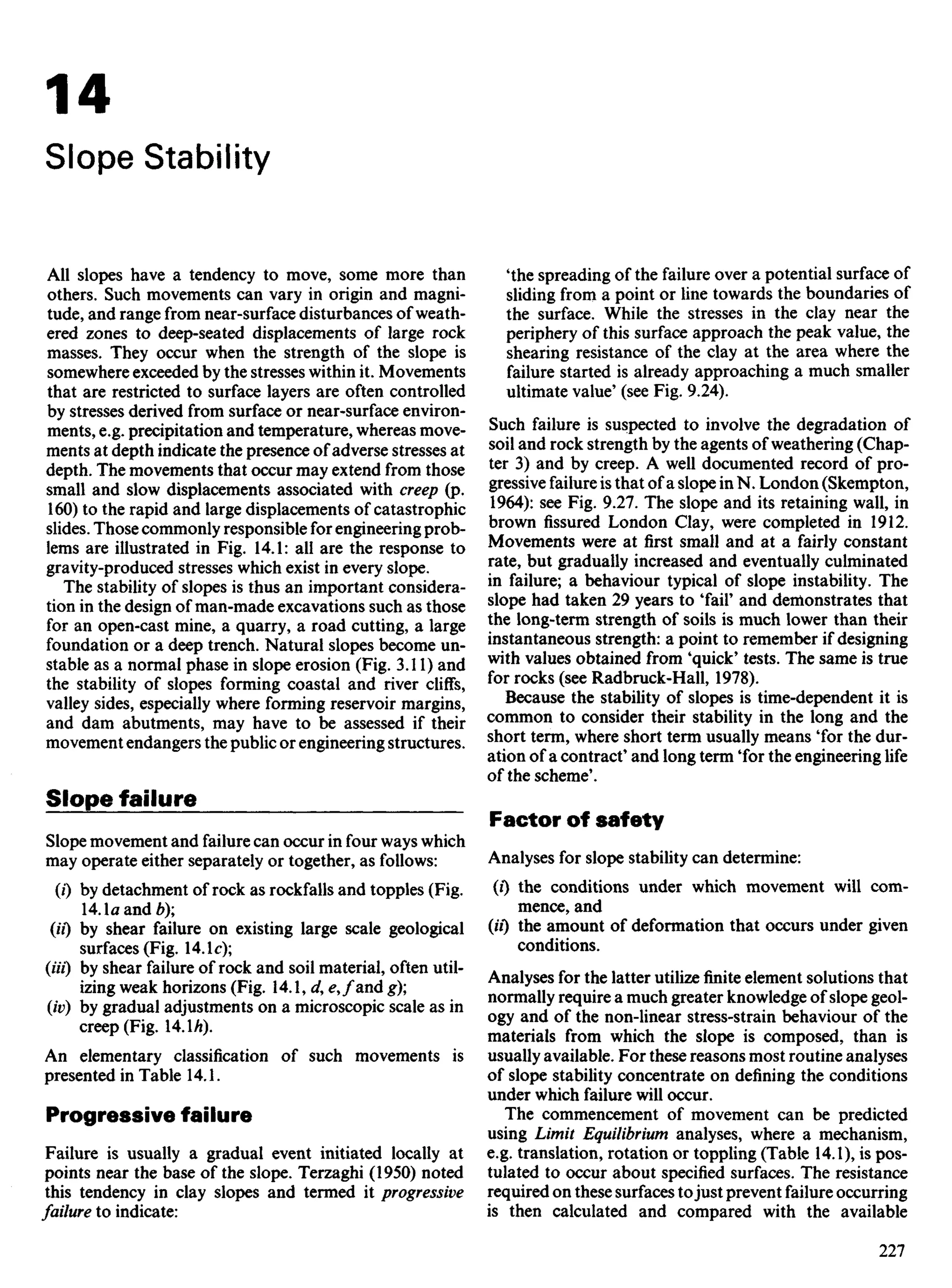
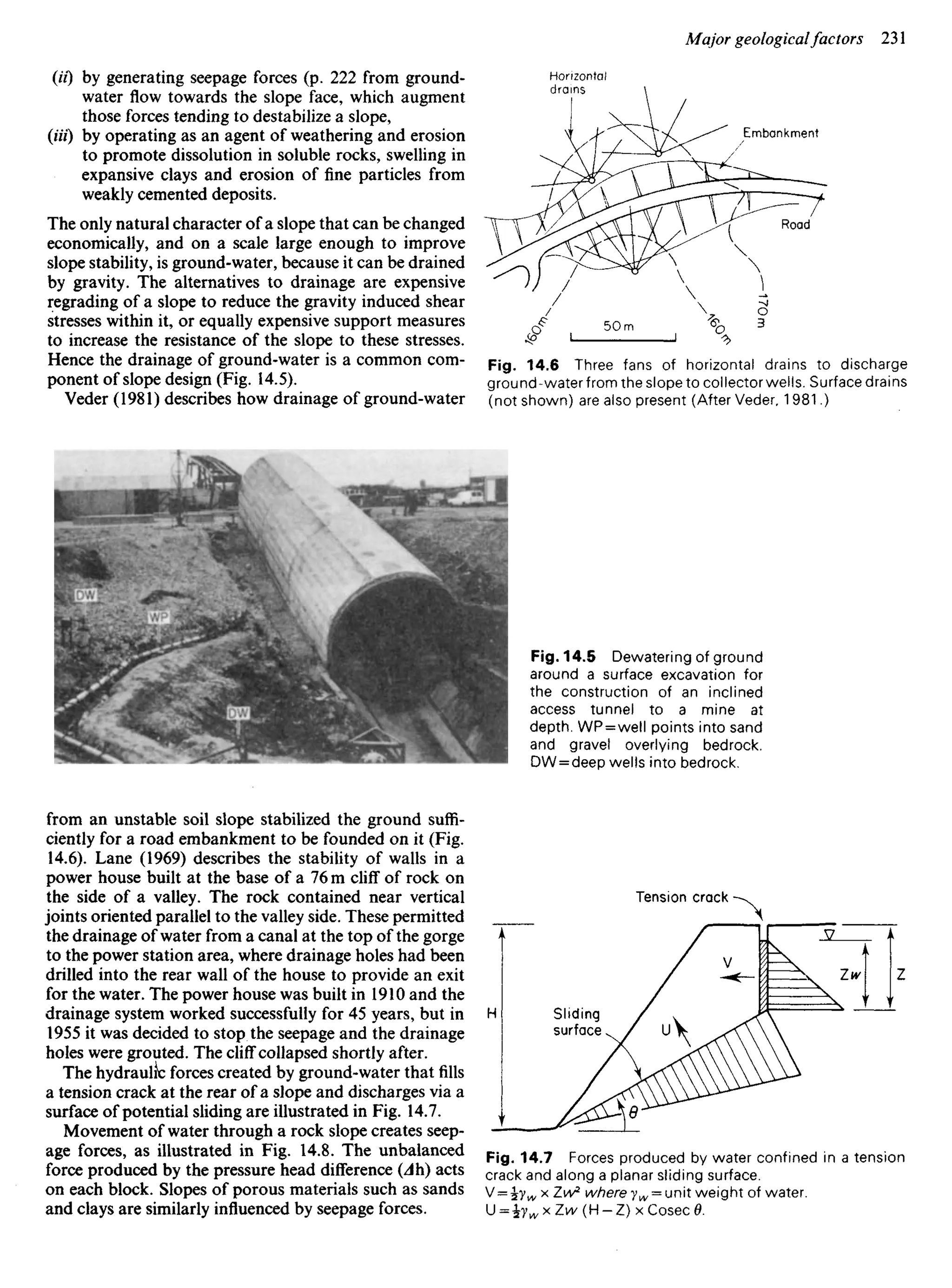
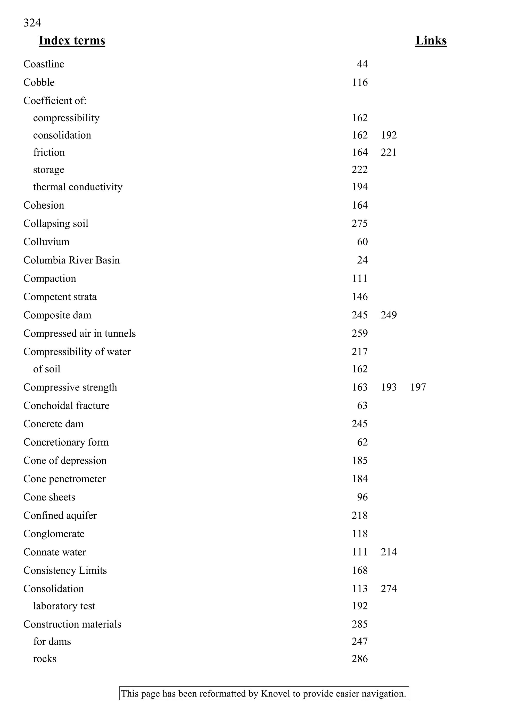
13.20« and 13.23). When the position of the divides does
not coincide, rainwater which percolates to the water table
will be carried, by ground-water flow, beneath the divide
of the surface catchment in which it fell: this is called
underflow (Fig. 18.1).
Water table
River
River
Fig. 18.1 On the left a map of a catchment: solid
line = topographic divide; broken line = ground-water divide;
arrows indicate underflow. Two vertical cross-sections illus-
trate the geological structures that result in this underflow;
arrows indicate movement of ground-water. GS = gauging
station for measuring river flow.
Water budgets
If more water is taken from the ground than enters it
from recharge (p. 214), water levels will fall and, in theory,
the ground will eventually be drained. The water budget
Table 18.1 Examples of water budgets
Mass balance for a budget
INFLOW =OUTFLOW +CHANGE IN
STORAGE
For a catchment (simple budget)
Precipitation = Evaporation + ^
Transpiration+ +Infiltration
River run-off J
For a catchment (more complex budget)
'evaporation+ ^
transpiration +
River run-off+ r Infiltration+ ^
Precipitation+ ^ pumped net change in
+ ve underflow+^= Jg r o u n d w a t e r + U J lake levels+ }
imports of water J ] _v e under- I artificial
flow+ exports I recharge J
of
, water
For an aquifer
Recharge =Ground-water+ Changes in
discharge water level x
coef, of storage](https://image.slidesharecdn.com/ageologyforengineersseventhedition-240123054612-a0c16209/75/A_Geology_for_Engineers_Seventh_Edition-pdf-266-2048.jpg)


![ANPARA THERMAL POWER STATION[1] sangam.pdf](https://cdn.slidesharecdn.com/ss_thumbnails/anparathermalpowerstation1sangam-251121115219-9261cde4-thumbnail.jpg?width=640&height=640&fit=bounds)


