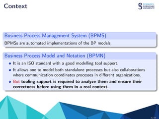
A Direct Formal Semantics for BPMN Time-Related
Constructs
Sara Houhou , Souheib Baarir, Pascal Poizat & Philippe Quéinnec
Sorbonne Université, CNRS, LIP6, F-75005, Paris, France
Biskra Université, LINFI, Biskra, Algeria
Montpellier Université, CNRS, LIRMM, F-34000, Montpelier, France
Universite Paris Lumiéres, Université Paris Nanterre, F-92000, Nanterre, France
IRIT - Universite de Toulouse, F-31000 Toulouse, France
April 26, 2021
Introduction (Context, Issue, Purpose)
Context
Business Process (BP)
A BP is a set of activities organized to achieve a goal.
Business Process Management
BPM is a method to continuously improve business processes in order to achieve
better results (design, enactment, diagnosis ).
Business Process Model
BP models are a key elements of BPM. They explicitly represent the BPs in terms
of their activities and the execution constraints between them.
2/26
Context
Business Process Management System (BPMS)
BPMSs are automated implementations of the BP models.
Business Process Model and Notation (BPMN)
It is an ISO standard with a good modelling tool support.
It allows one to model both standalone processes but also collaborations
where communication coordinates processes in different organizations.
But tooling support is required to analyze them and ensure their
correctness before using them in a real context.
3/26
Example
Running Example (Paper Review Process).
4/26
Example
Running Example (Paper Review Process).
Is this model Correct?
4/26
BPMN Specification : Issue
BPMN (now v2.02) is a comprehensive but complex notation
Its execution semantics is imprecise and ambiguous
I use of natural language & Dispersed through the standard
I no explicit formal semantics for BPMN time-related features in it
Tool make assumptions on the semantics.
Need for a precise operational semantics (with different perspectives : control
flow, Communication, and Time, Data)
5/26
Verification of BPMN in the Literature
There is (a large amount of) approaches using formal methods to give a formal
semantics to BPMN and supporting the time perspective but:
They rely on transformations to specific languages (Petri nets, Timed
Automata)
Some address elements such as OR join gateways, Sub-Processes (SP), Time
Events (TE), or collaboration but none is able to reason on collaboration
including all of them
Some propose to extend BPMN to support time patterns
None supports the different type of time information (date, cycle, duration)
associated to TE through use of ISO-8601 standard.
6/26
Supported BPMN subset
Events (E)
Start Events (SE)
NSE MSE
Intermediate Events (IE)
CMIE TMIE
End Events (EE)
NEE MEE
TEE
Gateways (G)
AND
XOR
OR
EB
Nodes
Pool
Lane
(P)
Activities (A)
Sub Process, expanded (SP)
Tasks (T)
AT RT ST
Boundary Events (BE)
MBE MBE (non interrupt.) Pool
Lane
(P)
RT
ST
Sequence Flows (SF)
Edges
NSF CSF DSF MF
TSE
TICE
TBE TBE (non interrupt.)
7/26
Synthetic View of Time-Related BPMN
BPMN Standard
TSE TICE
TBE TBE
TimerEventDefinition ISO-8601 Interrupt non-Interrupt
timeDate date and time yyyy-mm-ddThh:mm:ssZ ◦ ◦ ◦ ◦
timeCycle
unbounded
R/ yyyy-mm-ddThh:mm:ssZ / yyyy-mm-ddThh:mm:ssZ ◦ ◦ – ◦
R/ yyyy-mm-ddThh:mm:ssZ / PnYnMnDTnHnMnS ◦ ◦ – ◦
R/ PnYnMnDTnHnMnS/yyyy-mm-ddThh:mm:ssZ ◦ ◦ – ◦
R/PnYnMnDTnHnMnS ◦ ◦ – ◦
bounded
Rn/ yyyy-mm-ddThh:mm:ssZ/yyyy-mm-ddThh:mm:ssZ ◦ ◦ – ◦
Rn/ yyyy-mm-ddThh:mm:ssZ/PnYnMnDTnHnMnS ◦ ◦ – ◦
Rn/ PnYnMnDTnHnMnS/yyyy-mm-ddThh:mm:ssZ ◦ ◦ – ◦
Rn/ PnYnMnDTnHnMnS ◦ ◦ – ◦
timeDuration duration PnYnMnDTnHnMnS – ◦ ◦ ◦
Time-related features in BPMN and their relation to ISO-8601.
8/26
Issue
Research Question
How can we formalize the execution semantics of BPMN time constructs
(including relation to ISO-8601)?
9/26
Contribution
Our Process
10/26
Outline
BPMN Time-Contracts Formalization
Encoding the Semantics in Alloy
Verification Means
11/26
BPMN Time-Contracts Formalisation
Formalization of BPMN
First-Order logic (FOL)
I Expressive logic, to give a clear and non ambiguous semantics to BPMN.
I Not relying on the expressiveness of a targeted formal language, but directly of
the modeling language.
12/26
Formalization of BPMN
First-Order logic (FOL)
Model represented as a (labelled) graph
I Control flow elements → Nodes
I Sequence, Conditional, and Message Flows → Edges
I Kinds of elements in a BPMN model → Type labels in the graph
12/26
Formalization of BPMN
First-Order logic (FOL)
Model represented as a (labelled) graph
I Control flow elements → Nodes
I Sequence, Conditional, and Message Flows → Edges
I Kinds of elements in a BPMN model → Type labels in the graph
Semantics based on a token game follows the semi-formal semantics of the
standard.
I Set of rules describing how tokens move around nodes and edges to form a
complete execution
F St: enabling the node to start its execution
F Ct: enabling the node to complete its execution
I A global clock for the whole collaboration diagram & a local clock for each
timer node which has not date definition.
Properties are expressed using the Linear Temporal Logic (LTL)
12/26
Fixing the initial state
Tokens on all None Start Events
Global clock initialized to a specific date and time (w.r.t. an absolute date
and time)
Tokens on all Start Timer Events having a time value lower than the global
clock
All timer nodes local clocks initialized at 0
Initialize the Redundancy variable of each recurrent timer node to its
recurrence number
13/26
Fixing the initial state
gc = 2021−01−16 T 23 : 59
lc(BENI) = 0
lc(TCE2) = 0
rec(BENI) = 2
14/26
Distinguishing Timer Nodes
We define a set of timer types Timer = TSE ∪ TICE ∪ TBE Where:
Timer start events ( TSE) have a timeDate definition
Timer catching events (TICE) may have a timeDuration or a timeDate
definition. TICE = {TICEp, TICEd }
Timer Boundary Events (TBE) may be interrupting or not.
TBE = TBE
∪ TBE⊕
, with
I Interrupting TBEs nodes may have a timeDate or a timeDuration definition.
TBE
= {TBE
d , TBE
p }
I The non-Interrupting TBEs may have a timeDate, a timeDuration, or a
timeCycle definition. TBE⊕
= {TBE⊕
d , TBE⊕
p }∪ TBE⊕
c
15/26
Distinguishing Timer Nodes
The timeCycle definition may be defined based a number of recurrences for
the timer event triggers separated by
I a period and where the first trigger is done relatively to a fixed start date;
I a period and where the last trigger is done before the fixed end date;
I or only a period.
TBE⊕
c = {TBE⊕
c(start), TBE⊕
c(end), TBE⊕
c(p)}
With the same principle we have defined the set of types for all the other
supported nodes.
BPMN Standard
TSE TICE
TBE TBE
TimerEventDefinition ISO-8601 Interrupt non-Interrupt
timeDate date and time yyyy-mm-ddThh:mm:ssZ • • • •
timeCycle
unbounded
R/ yyyy-mm-ddThh:mm:ssZ / yyyy-mm-ddThh:mm:ssZ ◦ ◦ – ◦
R/ yyyy-mm-ddThh:mm:ssZ / PnYnMnDTnHnMnS ◦ ◦ – •
R/ PnYnMnDTnHnMnS/yyyy-mm-ddThh:mm:ssZ ◦ ◦ – •
R/PnYnMnDTnHnMnS ◦ ◦ – •
bounded
Rn/ yyyy-mm-ddThh:mm:ssZ/yyyy-mm-ddThh:mm:ssZ ◦ ◦ – ◦
Rn/ yyyy-mm-ddThh:mm:ssZ/PnYnMnDTnHnMnS ◦ ◦ – •
Rn/ PnYnMnDTnHnMnS/yyyy-mm-ddThh:mm:ssZ ◦ ◦ – •
Rn/ PnYnMnDTnHnMnS ◦ ◦ – •
timeDuration duration PnYnMnDTnHnMnS – • • •
Support: BPMN and us (•), BPMN only (◦).
15/26
Time Management
In order to manipulate the temporal information of each node, we define :
Ctime = {Tdate, Tduration, Tcycle}:
I timeDate, that specifies a fixed date and time
I timeCycle, that specifies repeating intervals
I timeDuration that specifies the amount of time a timer should run before firing
timeVal = Date ∪ Duration ∪ Cycle, with
I Date ⊆ N represents a date (and time) expressed in seconds;
I Duration ⊆ N represents a time duration in seconds;
I Cycle = (N ∪ {ι}) × [Duration ∪ (Date × Duration) ∪ (Duration × Date)],
represents a composite timing type.
I A set of execution rule for each node as a step
I A transition relation that specifies either a node may make a step (start or
complete)
16/26
Time Management
The transition relation will be executed according to the following steps:
If there are timer nodes that are active and are enabled to be complete,
they have the priority so:
I They will run one by one, each node runs according to its execution rule;
I During their execution neither the global clock nor their local clocks can be
incremented
If no timer node is ready to complete, and there is a non timer node may
start or complete then:
I This node may start or complete
I The time of all inactive timer nodes is freezed
I The local time of all active timer nodes advances
I The global clock advances
If no node may be execute and their is a timer nodes still active and they are
not ready to complete, time advances.
16/26
Example of execution rules
17/26
Example of execution rules (Zone1)
Completing behavior of Timer Start Event with Date Configuration. Before (left) and
after (right) application of the Ct rule.
18/26
Example of execution rules (Zone2)
Completing behavior of an Interrupting boundary Event with Date Configuration. Before
(left) and after (right) application of the Ct rule.
19/26
Example of execution rules (Zone3)
Starting behaviour of a Receive Task.
20/26
Example of execution rules (Zone3)
Starting behavior of a recurrent non-interrupting Timer Boundary Event configured to
two recurrences, 15 days between them, may be execute before a date and time
(2021-04-29 T 00:00:00). (First reccurence)
20/26
Example of execution rules (Zone3)
Completing behaviour of a Receive Task.
20/26
Example of execution rules (Zone3)
Starting behavior of a recurrent non-interrupting Timer Boundary Event configured to
two recurrences, 15 days between them, may be execute before a date and time
(2021-04-29 T 00:00:00). (Second recurrence)
20/26
Example of execution rules (Zone5)
Completing behavior of an Event-Based Gateway: no message received and waiting time
reaches the deadline.
21/26
Example of execution rules (Zone5)
Completing behavior of a Timer Catch Event : duration configured to 120 days.
21/26
Encoding the Semantics in Alloy
Implementation
22/26
Verification Means
Correctness Properties
Two kinds of verification are available:
checks on the structure itself (i.e., assertions ensure that the model is
well-formed, e.g., a message flow connects two distinct processes)
checks on the executions, predicates on States are used to express properties
on executions. We have defined :
I Simple Termination, a predicate that states that every process reaches a state
where an End Event owns a token
I Correct Termination, a predicate that states that the whole system reaches a
state where all processes have terminated with an End Event and no token are
left on other nodes or edges
I MaxTime, a predicate that states that the whole system reaches a final state
before a given maximal time
I MinTime, a predicate that states that the wholes system takes at least a given
minimal time to reach a final state
23/26
Conclusion  Perspectives
Conclusion
First-order logic (FOL) formalization of the BPMN execution semantics
Handles control flow, sub-processes, communication, and time in a unified
way
Implementation in the Alloy language
No verification expertise required
Free and open source tool support
fbpmn: https://github.com/pascalpoizat/fbpmn
24/26
Perspectives
Evaluate the proposal on more examples
Dealing with greater BPMN subsets
(Data, multi-instance, correlation)
Add more properties to verify
Implement the proposal into the SMT-lib input language to adress the
verification issues
25/26
26/26

A Direct Formal Semantics for BPMN Time-Related Constructs Presentation

  • 1.
    A Direct FormalSemantics for BPMN Time-Related Constructs Sara Houhou , Souheib Baarir, Pascal Poizat & Philippe Quéinnec Sorbonne Université, CNRS, LIP6, F-75005, Paris, France Biskra Université, LINFI, Biskra, Algeria Montpellier Université, CNRS, LIRMM, F-34000, Montpelier, France Universite Paris Lumiéres, Université Paris Nanterre, F-92000, Nanterre, France IRIT - Universite de Toulouse, F-31000 Toulouse, France April 26, 2021
  • 2.
  • 3.
    Context Business Process (BP) ABP is a set of activities organized to achieve a goal. Business Process Management BPM is a method to continuously improve business processes in order to achieve better results (design, enactment, diagnosis ). Business Process Model BP models are a key elements of BPM. They explicitly represent the BPs in terms of their activities and the execution constraints between them. 2/26
  • 4.
    Context Business Process ManagementSystem (BPMS) BPMSs are automated implementations of the BP models. Business Process Model and Notation (BPMN) It is an ISO standard with a good modelling tool support. It allows one to model both standalone processes but also collaborations where communication coordinates processes in different organizations. But tooling support is required to analyze them and ensure their correctness before using them in a real context. 3/26
  • 5.
    Example Running Example (PaperReview Process). 4/26
  • 6.
    Example Running Example (PaperReview Process). Is this model Correct? 4/26
  • 7.
    BPMN Specification :Issue BPMN (now v2.02) is a comprehensive but complex notation Its execution semantics is imprecise and ambiguous I use of natural language & Dispersed through the standard I no explicit formal semantics for BPMN time-related features in it Tool make assumptions on the semantics. Need for a precise operational semantics (with different perspectives : control flow, Communication, and Time, Data) 5/26
  • 8.
    Verification of BPMNin the Literature There is (a large amount of) approaches using formal methods to give a formal semantics to BPMN and supporting the time perspective but: They rely on transformations to specific languages (Petri nets, Timed Automata) Some address elements such as OR join gateways, Sub-Processes (SP), Time Events (TE), or collaboration but none is able to reason on collaboration including all of them Some propose to extend BPMN to support time patterns None supports the different type of time information (date, cycle, duration) associated to TE through use of ISO-8601 standard. 6/26
  • 9.
    Supported BPMN subset Events(E) Start Events (SE) NSE MSE Intermediate Events (IE) CMIE TMIE End Events (EE) NEE MEE TEE Gateways (G) AND XOR OR EB Nodes Pool Lane (P) Activities (A) Sub Process, expanded (SP) Tasks (T) AT RT ST Boundary Events (BE) MBE MBE (non interrupt.) Pool Lane (P) RT ST Sequence Flows (SF) Edges NSF CSF DSF MF TSE TICE TBE TBE (non interrupt.) 7/26
  • 10.
    Synthetic View ofTime-Related BPMN BPMN Standard TSE TICE TBE TBE TimerEventDefinition ISO-8601 Interrupt non-Interrupt timeDate date and time yyyy-mm-ddThh:mm:ssZ ◦ ◦ ◦ ◦ timeCycle unbounded R/ yyyy-mm-ddThh:mm:ssZ / yyyy-mm-ddThh:mm:ssZ ◦ ◦ – ◦ R/ yyyy-mm-ddThh:mm:ssZ / PnYnMnDTnHnMnS ◦ ◦ – ◦ R/ PnYnMnDTnHnMnS/yyyy-mm-ddThh:mm:ssZ ◦ ◦ – ◦ R/PnYnMnDTnHnMnS ◦ ◦ – ◦ bounded Rn/ yyyy-mm-ddThh:mm:ssZ/yyyy-mm-ddThh:mm:ssZ ◦ ◦ – ◦ Rn/ yyyy-mm-ddThh:mm:ssZ/PnYnMnDTnHnMnS ◦ ◦ – ◦ Rn/ PnYnMnDTnHnMnS/yyyy-mm-ddThh:mm:ssZ ◦ ◦ – ◦ Rn/ PnYnMnDTnHnMnS ◦ ◦ – ◦ timeDuration duration PnYnMnDTnHnMnS – ◦ ◦ ◦ Time-related features in BPMN and their relation to ISO-8601. 8/26
  • 11.
    Issue Research Question How canwe formalize the execution semantics of BPMN time constructs (including relation to ISO-8601)? 9/26
  • 12.
  • 13.
  • 14.
    Outline BPMN Time-Contracts Formalization Encodingthe Semantics in Alloy Verification Means 11/26
  • 15.
  • 16.
    Formalization of BPMN First-Orderlogic (FOL) I Expressive logic, to give a clear and non ambiguous semantics to BPMN. I Not relying on the expressiveness of a targeted formal language, but directly of the modeling language. 12/26
  • 17.
    Formalization of BPMN First-Orderlogic (FOL) Model represented as a (labelled) graph I Control flow elements → Nodes I Sequence, Conditional, and Message Flows → Edges I Kinds of elements in a BPMN model → Type labels in the graph 12/26
  • 18.
    Formalization of BPMN First-Orderlogic (FOL) Model represented as a (labelled) graph I Control flow elements → Nodes I Sequence, Conditional, and Message Flows → Edges I Kinds of elements in a BPMN model → Type labels in the graph Semantics based on a token game follows the semi-formal semantics of the standard. I Set of rules describing how tokens move around nodes and edges to form a complete execution F St: enabling the node to start its execution F Ct: enabling the node to complete its execution I A global clock for the whole collaboration diagram & a local clock for each timer node which has not date definition. 12/26
  • 19.
    Formalization of BPMN First-Orderlogic (FOL) Model represented as a (labelled) graph I Control flow elements → Nodes I Sequence, Conditional, and Message Flows → Edges I Kinds of elements in a BPMN model → Type labels in the graph Semantics based on a token game follows the semi-formal semantics of the standard. I Set of rules describing how tokens move around nodes and edges to form a complete execution F St: enabling the node to start its execution F Ct: enabling the node to complete its execution I A global clock for the whole collaboration diagram & a local clock for each timer node which has not date definition. Properties are expressed using the Linear Temporal Logic (LTL) 12/26
  • 20.
    Fixing the initialstate Tokens on all None Start Events Global clock initialized to a specific date and time (w.r.t. an absolute date and time) Tokens on all Start Timer Events having a time value lower than the global clock All timer nodes local clocks initialized at 0 Initialize the Redundancy variable of each recurrent timer node to its recurrence number 13/26
  • 21.
    Fixing the initialstate gc = 2021−01−16 T 23 : 59 lc(BENI) = 0 lc(TCE2) = 0 rec(BENI) = 2 14/26
  • 22.
    Distinguishing Timer Nodes Wedefine a set of timer types Timer = TSE ∪ TICE ∪ TBE Where: Timer start events ( TSE) have a timeDate definition Timer catching events (TICE) may have a timeDuration or a timeDate definition. TICE = {TICEp, TICEd } Timer Boundary Events (TBE) may be interrupting or not. TBE = TBE ∪ TBE⊕ , with I Interrupting TBEs nodes may have a timeDate or a timeDuration definition. TBE = {TBE d , TBE p } I The non-Interrupting TBEs may have a timeDate, a timeDuration, or a timeCycle definition. TBE⊕ = {TBE⊕ d , TBE⊕ p }∪ TBE⊕ c 15/26
  • 23.
    Distinguishing Timer Nodes ThetimeCycle definition may be defined based a number of recurrences for the timer event triggers separated by I a period and where the first trigger is done relatively to a fixed start date; I a period and where the last trigger is done before the fixed end date; I or only a period. TBE⊕ c = {TBE⊕ c(start), TBE⊕ c(end), TBE⊕ c(p)} With the same principle we have defined the set of types for all the other supported nodes. BPMN Standard TSE TICE TBE TBE TimerEventDefinition ISO-8601 Interrupt non-Interrupt timeDate date and time yyyy-mm-ddThh:mm:ssZ • • • • timeCycle unbounded R/ yyyy-mm-ddThh:mm:ssZ / yyyy-mm-ddThh:mm:ssZ ◦ ◦ – ◦ R/ yyyy-mm-ddThh:mm:ssZ / PnYnMnDTnHnMnS ◦ ◦ – • R/ PnYnMnDTnHnMnS/yyyy-mm-ddThh:mm:ssZ ◦ ◦ – • R/PnYnMnDTnHnMnS ◦ ◦ – • bounded Rn/ yyyy-mm-ddThh:mm:ssZ/yyyy-mm-ddThh:mm:ssZ ◦ ◦ – ◦ Rn/ yyyy-mm-ddThh:mm:ssZ/PnYnMnDTnHnMnS ◦ ◦ – • Rn/ PnYnMnDTnHnMnS/yyyy-mm-ddThh:mm:ssZ ◦ ◦ – • Rn/ PnYnMnDTnHnMnS ◦ ◦ – • timeDuration duration PnYnMnDTnHnMnS – • • • Support: BPMN and us (•), BPMN only (◦). 15/26
  • 24.
    Time Management In orderto manipulate the temporal information of each node, we define : Ctime = {Tdate, Tduration, Tcycle}: I timeDate, that specifies a fixed date and time I timeCycle, that specifies repeating intervals I timeDuration that specifies the amount of time a timer should run before firing timeVal = Date ∪ Duration ∪ Cycle, with I Date ⊆ N represents a date (and time) expressed in seconds; I Duration ⊆ N represents a time duration in seconds; I Cycle = (N ∪ {ι}) × [Duration ∪ (Date × Duration) ∪ (Duration × Date)], represents a composite timing type. I A set of execution rule for each node as a step I A transition relation that specifies either a node may make a step (start or complete) 16/26
  • 25.
    Time Management The transitionrelation will be executed according to the following steps: If there are timer nodes that are active and are enabled to be complete, they have the priority so: I They will run one by one, each node runs according to its execution rule; I During their execution neither the global clock nor their local clocks can be incremented If no timer node is ready to complete, and there is a non timer node may start or complete then: I This node may start or complete I The time of all inactive timer nodes is freezed I The local time of all active timer nodes advances I The global clock advances If no node may be execute and their is a timer nodes still active and they are not ready to complete, time advances. 16/26
  • 26.
  • 27.
    Example of executionrules (Zone1) Completing behavior of Timer Start Event with Date Configuration. Before (left) and after (right) application of the Ct rule. 18/26
  • 28.
    Example of executionrules (Zone2) Completing behavior of an Interrupting boundary Event with Date Configuration. Before (left) and after (right) application of the Ct rule. 19/26
  • 29.
    Example of executionrules (Zone3) Starting behaviour of a Receive Task. 20/26
  • 30.
    Example of executionrules (Zone3) Starting behavior of a recurrent non-interrupting Timer Boundary Event configured to two recurrences, 15 days between them, may be execute before a date and time (2021-04-29 T 00:00:00). (First reccurence) 20/26
  • 31.
    Example of executionrules (Zone3) Completing behaviour of a Receive Task. 20/26
  • 32.
    Example of executionrules (Zone3) Starting behavior of a recurrent non-interrupting Timer Boundary Event configured to two recurrences, 15 days between them, may be execute before a date and time (2021-04-29 T 00:00:00). (Second recurrence) 20/26
  • 33.
    Example of executionrules (Zone5) Completing behavior of an Event-Based Gateway: no message received and waiting time reaches the deadline. 21/26
  • 34.
    Example of executionrules (Zone5) Completing behavior of a Timer Catch Event : duration configured to 120 days. 21/26
  • 35.
  • 36.
  • 37.
  • 38.
    Correctness Properties Two kindsof verification are available: checks on the structure itself (i.e., assertions ensure that the model is well-formed, e.g., a message flow connects two distinct processes) checks on the executions, predicates on States are used to express properties on executions. We have defined : I Simple Termination, a predicate that states that every process reaches a state where an End Event owns a token I Correct Termination, a predicate that states that the whole system reaches a state where all processes have terminated with an End Event and no token are left on other nodes or edges I MaxTime, a predicate that states that the whole system reaches a final state before a given maximal time I MinTime, a predicate that states that the wholes system takes at least a given minimal time to reach a final state 23/26
  • 39.
  • 40.
    Conclusion First-order logic (FOL)formalization of the BPMN execution semantics Handles control flow, sub-processes, communication, and time in a unified way Implementation in the Alloy language No verification expertise required Free and open source tool support fbpmn: https://github.com/pascalpoizat/fbpmn 24/26
  • 41.
    Perspectives Evaluate the proposalon more examples Dealing with greater BPMN subsets (Data, multi-instance, correlation) Add more properties to verify Implement the proposal into the SMT-lib input language to adress the verification issues 25/26
  • 42.