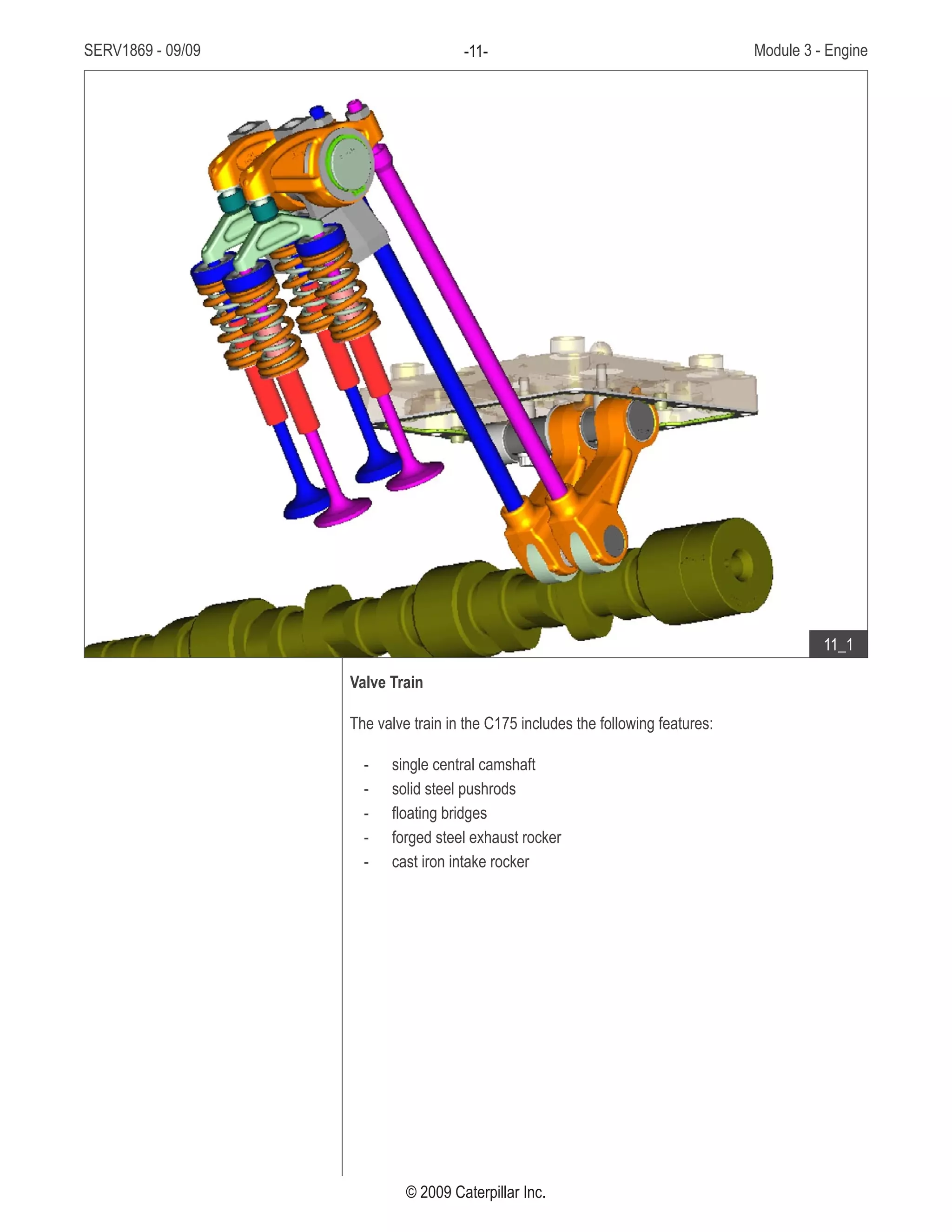
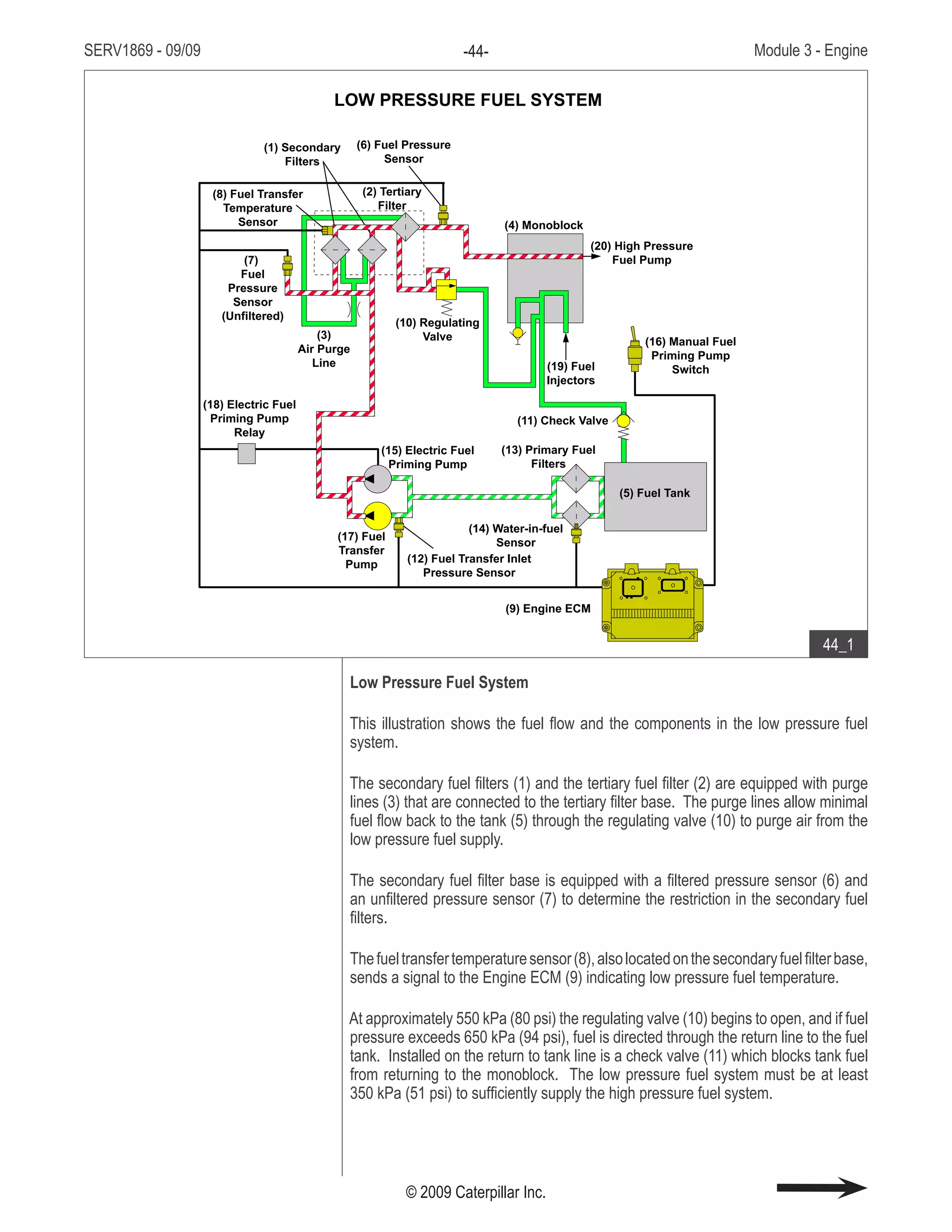
1. The document provides an overview of the key components and features of the C175 engine used in 793F off-highway trucks, including the high pressure common rail fuel system, air-to-air aftercooler, and increased horsepower.
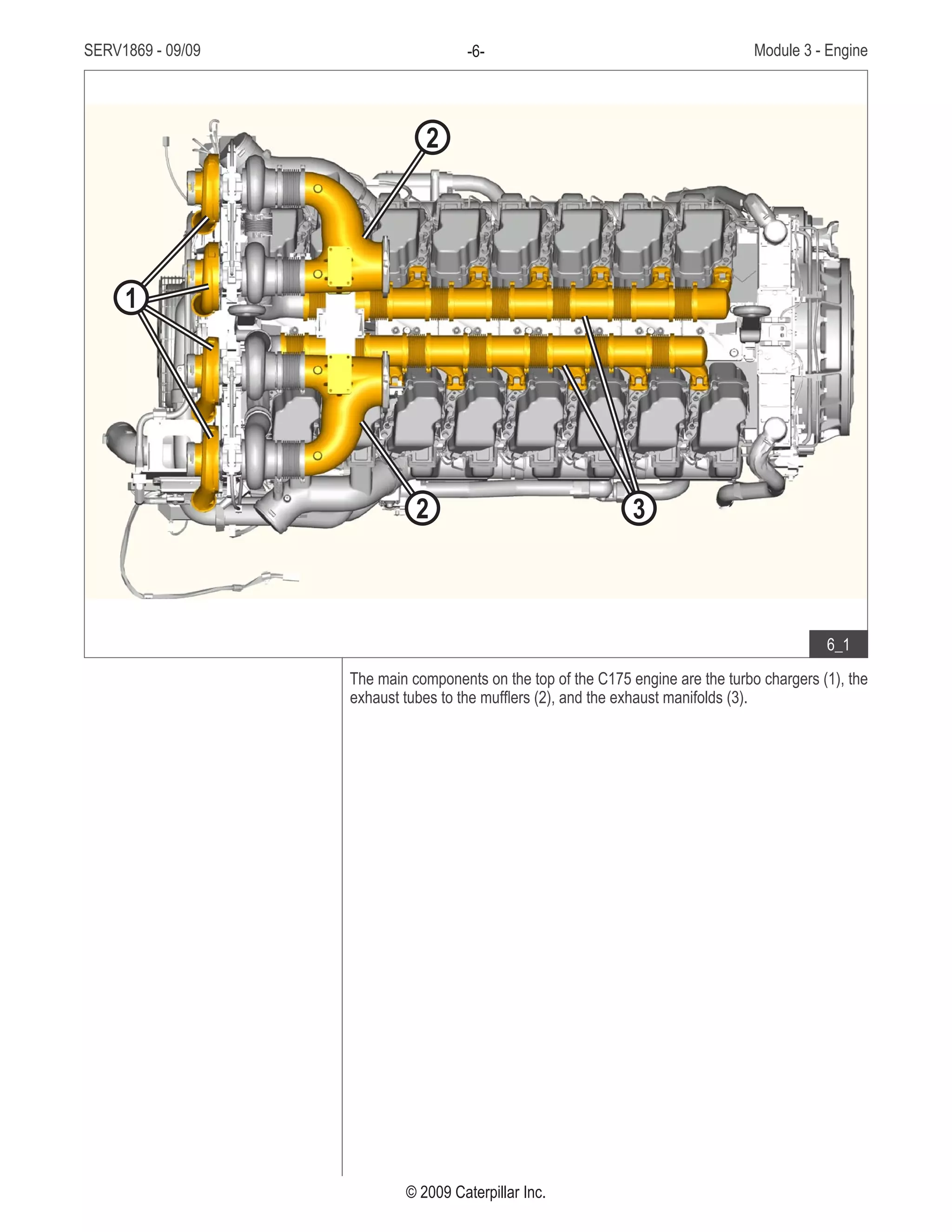
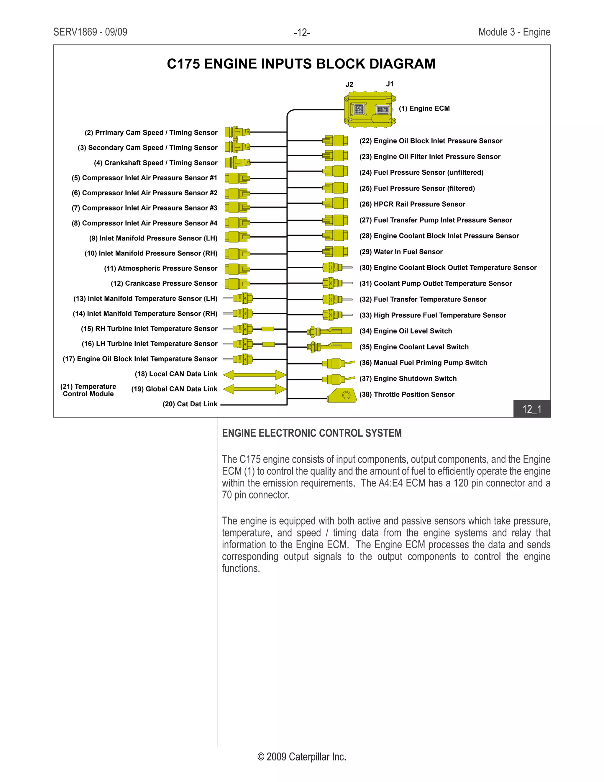
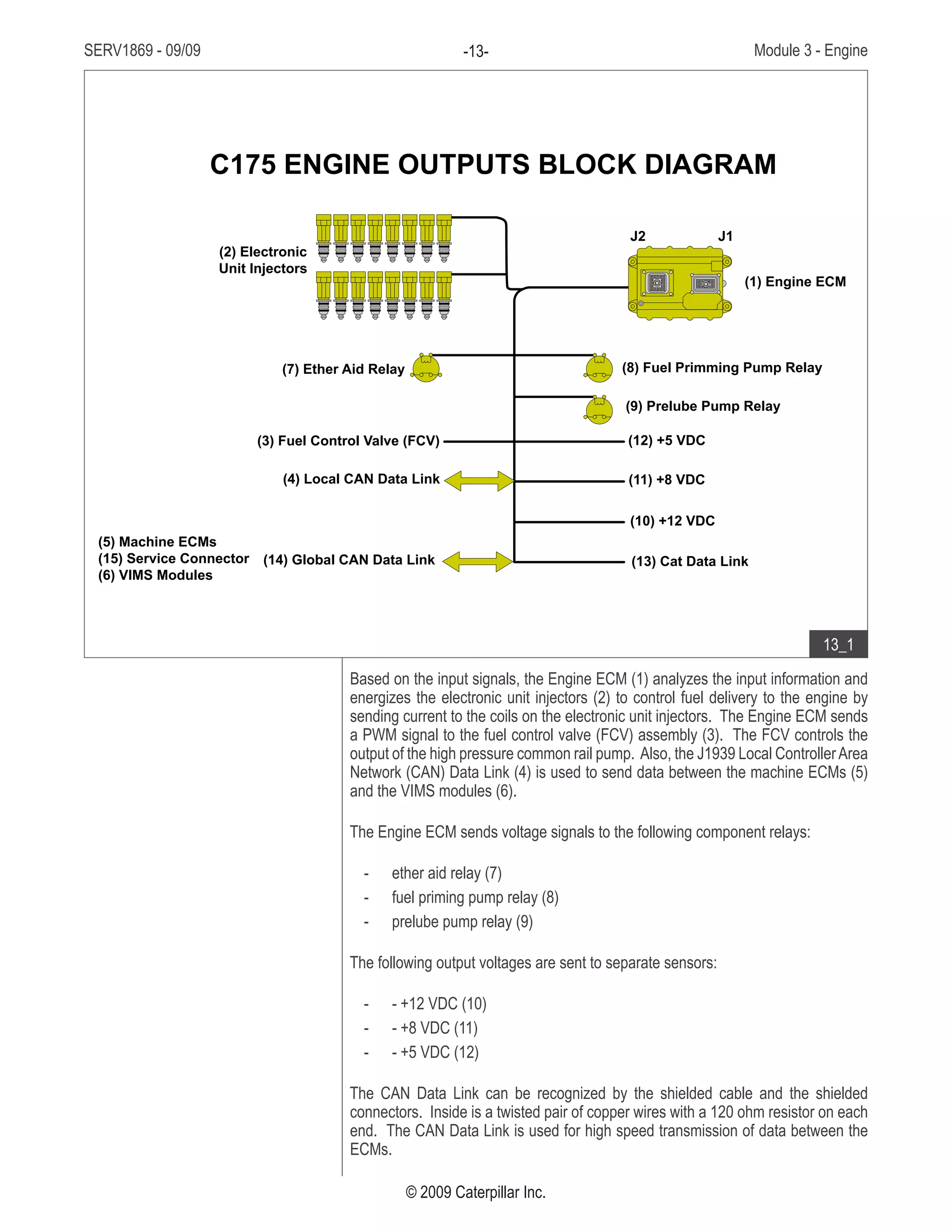
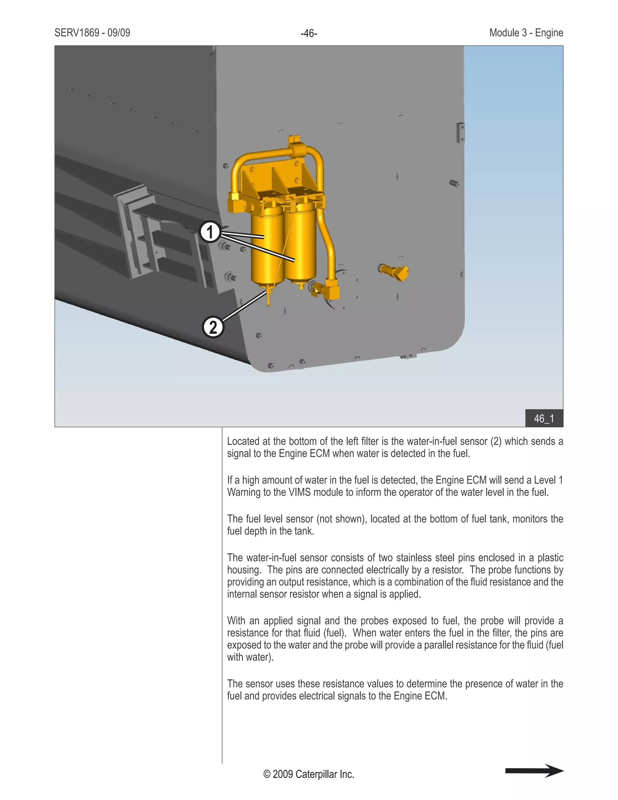
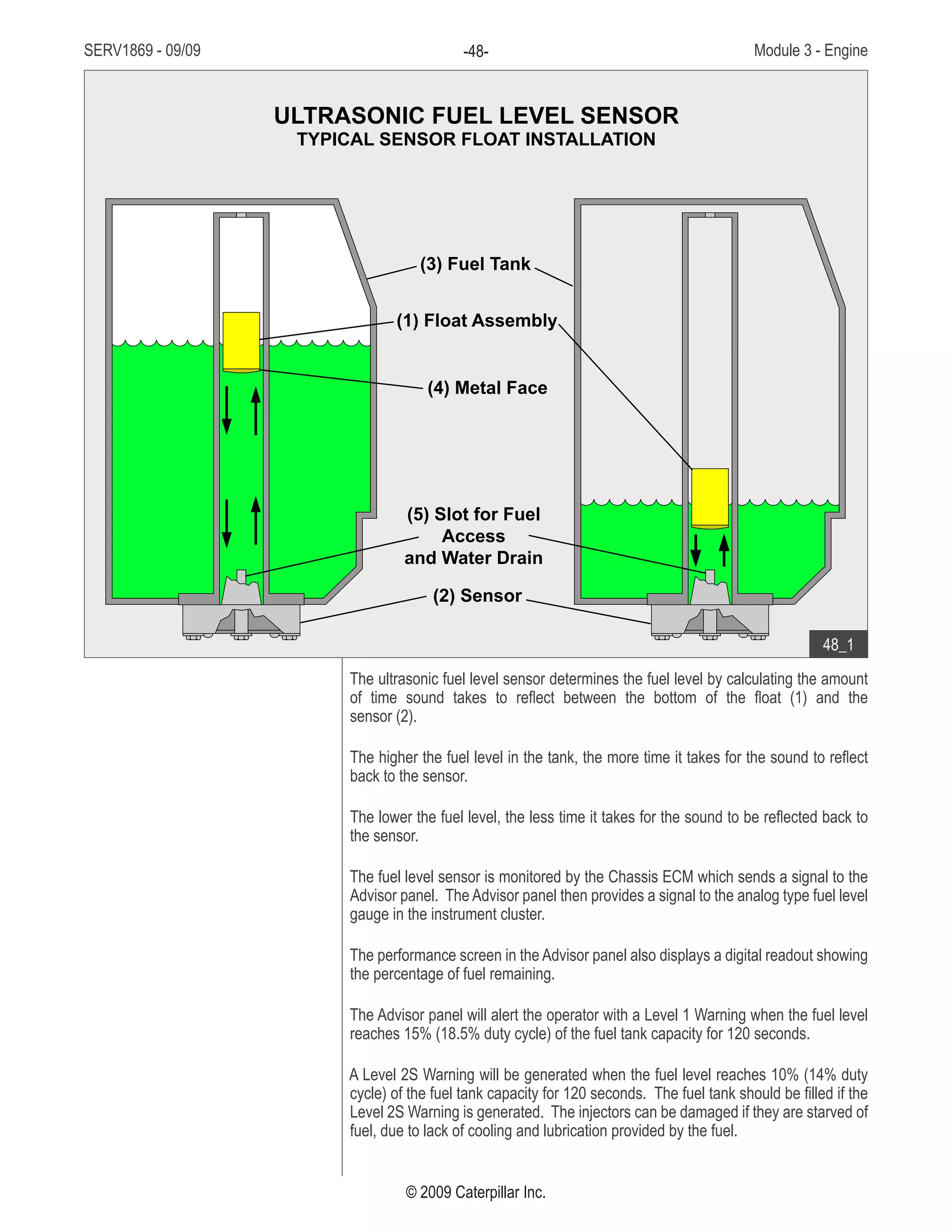
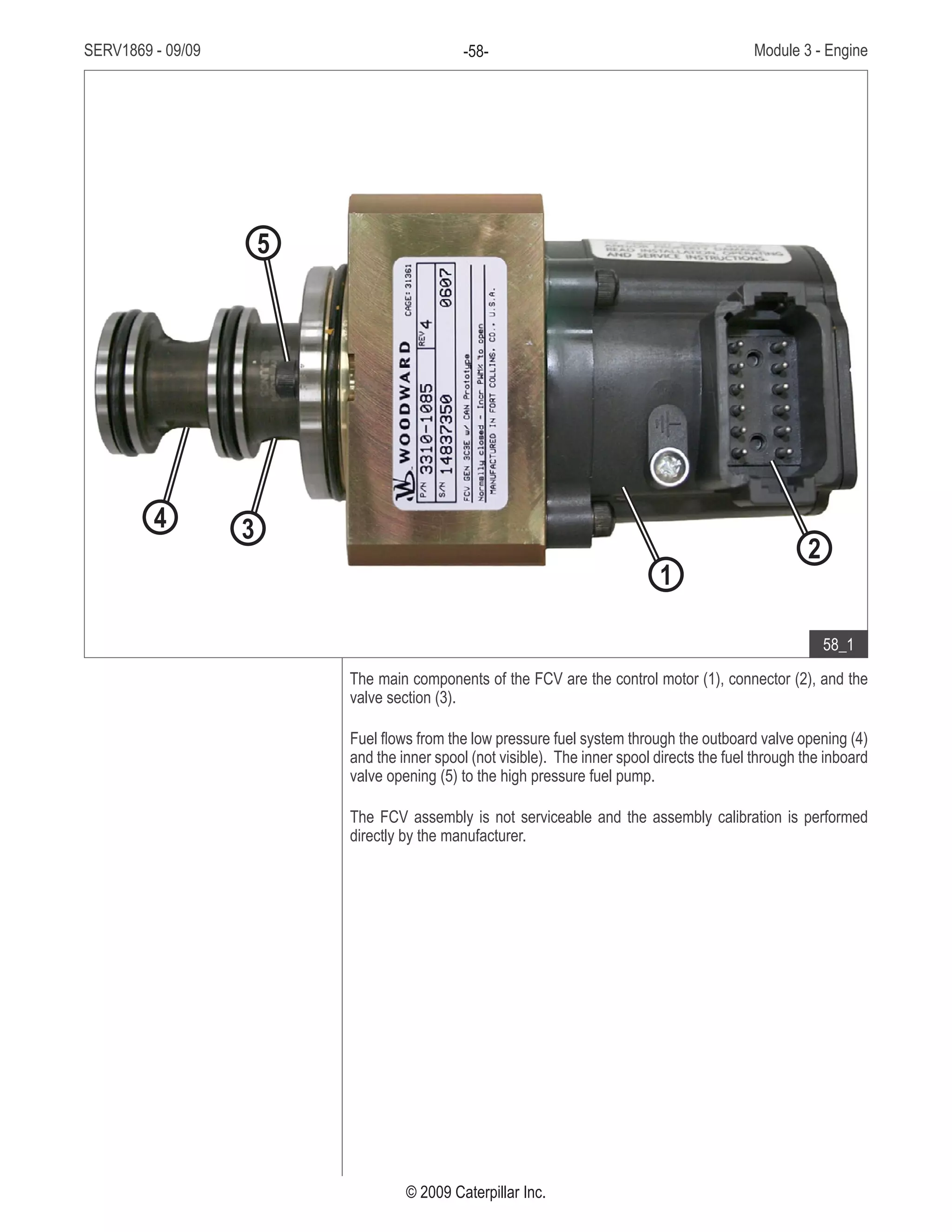
2. It describes the main components on the different sides of the engine such as the high pressure fuel rail and intake manifold on the right side and the coolant pump and oil pump on the left side.
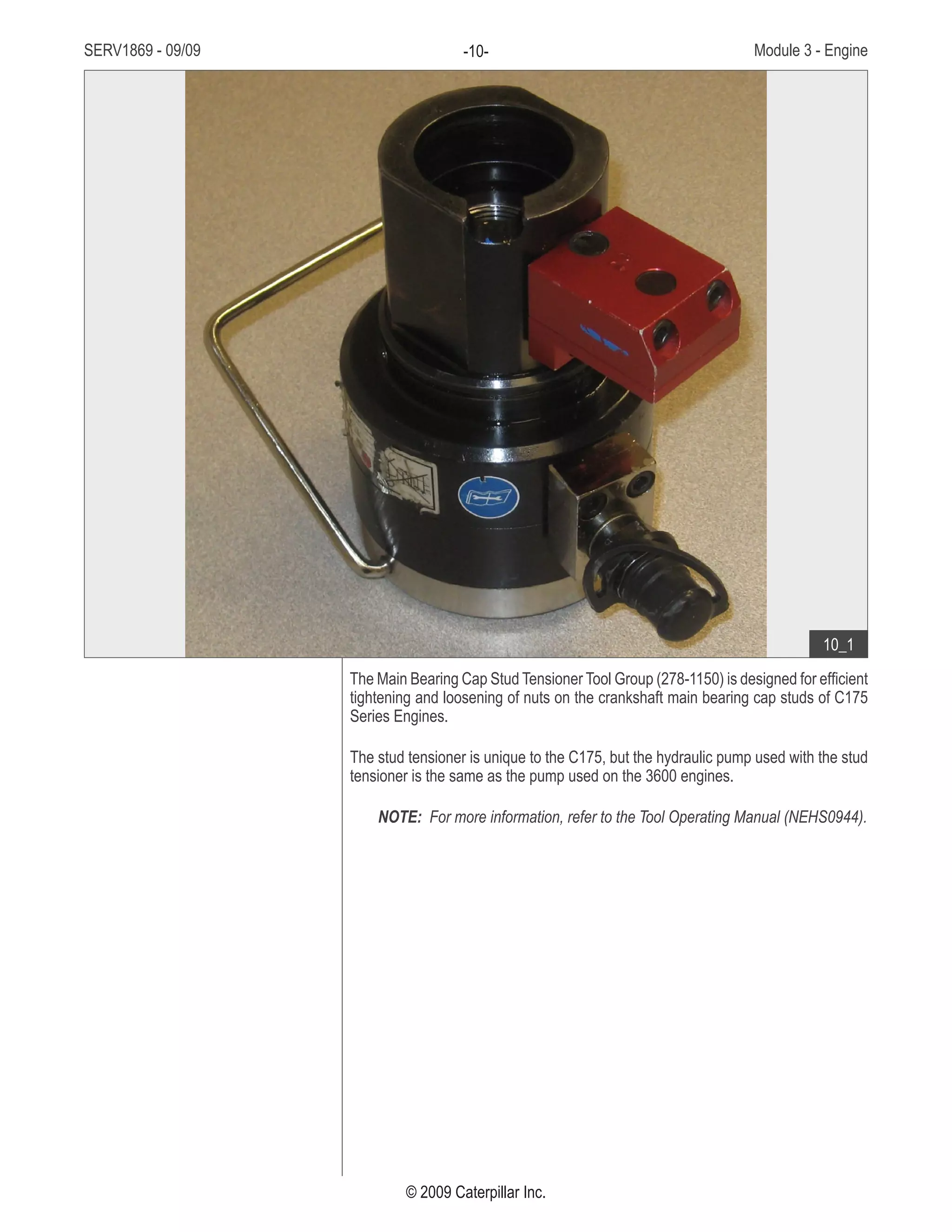
3. Special tools are required to work on certain engine components like the cylinder pack installation tool and connecting rod guides tool.


![Transmision contraeje[1]](https://cdn.slidesharecdn.com/ss_thumbnails/transmisioncontraeje1-201124172008-thumbnail.jpg?width=640&height=640&fit=bounds)


