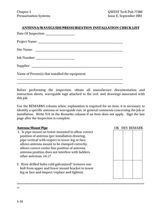
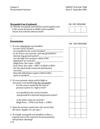
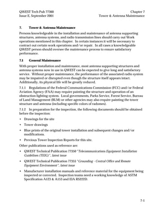
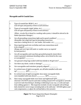
QWEST Communications
International Inc.
Technical Publication
Specification Standards For
Antenna And Waveguide
Installation, Removal And
Tower/Antenna Maintenance
Copyright 1984, 1996, 2000, 2001 77360
QWEST Communications International Inc. Issue E
All Rights Reserved September 2001
QWEST Tech Pub 77360 Notice
Issue E, September 2001
Throughout this publication, the term QWEST signifies QWEST Communications
International Inc.
NOTICE
This Technical Publication is intended to outline performance standards for Service
Suppliers performing installation, maintenance, rearrangement or removal work at
QWEST radio locations. It establishes guidelines for installation and removal of
antennas, transmission lines and for testing and pressurization of same. Guidelines for
conducting work operations at QWEST sites, including provisions for safety,
continuity of service and compliance with Federal Communications Commission
(FCC) and FAA OSHA requirements are also outlined. This Technical Publication
applies to any Service Supplier or Subcontractor performing such work either on
behalf of QWEST or a tenant organization at QWEST radio tower locations. As used in
the publication, the term "Supplier" shall mean "Service Supplier".
QWEST reserves the right to revise this document for any reason, including but not
limited to, conformity with standards promulgated by various governmental or
regulatory agencies; utilization of advances in the state of the technical arts; or to
reflect changes in the design of equipment, techniques, or procedures described or
referred to herein.
Liability to anyone arising out of use or reliance upon any information set forth herein
is expressly disclaimed, and no representation or warranties, expressed or implied, are
made with respect to the accuracy or utility of any information set forth herein.
This document is not to be construed as a suggestion to any manufacturer to modify or
change any of its products, nor does this publication represent any commitment by
QWEST to purchase any specific products. Further, conformance to this publication
does not constitute a guarantee of a given supplier's equipment and/or its associated
documentation.
Ordering information for QWEST Publications can be obtained from the Reference
Section of this document.
If further information is required, please contact:
QWEST Communications International Inc.
Manager – New Services Planning
700 W. Mineral Ave. MN-F15.15
Littleton, CO 80120
(303) 707-7107
(303) 707-9497 Fax #
E-mail: jhsmit2@qwest.com
QWEST Tech Pub 77360 Comments
Issue E, September 2001
COMMENTS on PUB 77360
PLEASE TEAR OUT AND SEND YOUR COMMENTS/SUGGESTIONS TO:
QWEST Corporation
Manager – New Services Planning
700 W. Mineral Ave. MN-F15.15
Littleton, CO 80120
(303) 707-7107
(303) 707-9497 Fax #
E-mail: jhsmit2@qwest.com
Information from you helps us to improve our Publications. Please take a few
moments to answer the following questions and return to the above address.
Was this Publication valuable to you in understanding
The technical parameters of our service? YES ______ NO ______
Was the information accurate and up-to-date? YES ______ NO ______
Was the information easily understood? YES ______ NO ______
Were the contents logically sequenced? YES ______ NO ______
Were the tables and figures understandable and helpful YES ______ NO ______
Were the pages legible? YES ______ NO ______
If you answered NO to any of the questions and/or if you have any other comments or
suggestions, please explain:
__________________________________________________________________
___________________________________________________________________
___________________________________________________________________
(Attach additional sheet, if necessary)
Name __________________________________________ Date _____________________
Company
__________________________________________________________________________
Address __________________________________________________________________
Telephone Number
__________________________________________________________________________
E-Mail ___________________________________________________________________
QWEST Tech Pub 77360 Table of Contents
Issue E, September 2001
TOC-i
CONTENTS
Chapter and Section Page
1. Introduction............................................................................................................. 1-1
1.1 General ......................................................................................................... 1-1
1.2 Reason For Reissue ..................................................................................... 1-1
2. General Provisions.................................................................................................. 2-1
2.1 QWEST Representative.............................................................................. 2-1
2.2 FCC Permit................................................................................................... 2-1
2.3 Surveying ..................................................................................................... 2-1
2.4 Installation and Removal Requirements................................................. 2-1
2.5 Precautions................................................................................................... 2-2
2.6 Radiation Hazard on Working Systems.................................................. 2-2
2.7 Transportation............................................................................................. 2-3
2.8 Materials....................................................................................................... 2-3
2.9 Substitutions Or Variations....................................................................... 2-3
2.10 Documentation............................................................................................ 2-3
2.11 Cleaning ....................................................................................................... 2-4
2.12 Temporary Toilets....................................................................................... 2-4
2.13 Welding ........................................................................................................ 2-4
2.14 Cut, Welded Or Damaged Surfaces......................................................... 2-4
2.15 Surplus Material.......................................................................................... 2-4
2.16 Storage of Material on the Site................................................................. 2-5
2.17 Protection of the Public ............................................................................. 2-5
2.18 Overtime Work ........................................................................................... 2-5
2.19 Safety ............................................................................................................ 2-5
2.20 Pre-construction Conference .................................................................... 2-5
2.21 Use of Sub-contractors............................................................................... 2-5
3. Antennas Installation............................................................................................. 3-1
3.1 General ......................................................................................................... 3-1
3.2 Antenna Installation (Horn, Parabolic, And Yagi/Whip)................... 3-2
3.3 Antenna Heater Circuit............................................................................. 3-4
Table of Contents QWEST Tech Pub 77360
Issue E, September 2001
TOC-ii
CONTENTS (Continued)
Chapter and Section Page
4. Transmission Lines................................................................................................. 4-1
4.1 General ......................................................................................................... 4-2
4.2 Waveguide ................................................................................................... 4-2
4.2.1 Bent Circular Rigid Waveguide.................................................... 4-2
4.2.2 Rigid Circular Waveguide............................................................. 4-2
4.2.3 Rectangular Waveguide................................................................. 4-2
4.2.4 Flexible Rectangular and Circular Waveguide .......................... 4-2
4.2.5 Rigid Rectangular Waveguide ...................................................... 4-2
4.3 Weather Seals.............................................................................................. 4-3
4.4 Transmission Line Installation (General) ............................................... 4-3
4.5 Elliptical Waveguide and Coaxial Cable Installation ........................... 4-5
4.5.1 Elliptical Waveguide Installation................................................. 4-5
4.5.2 Coaxial Cable Installation.............................................................. 4-7
4.6 Miscellaneous Waveguide Components................................................. 4-7
4.7 Waveguide/Antenna Leakage Test......................................................... 4-8
4.8 Electrical Tests............................................................................................. 4-8
4.9 Waveguide/Transmission Line Grounding ........................................... 4-9
5. Pressurization Systems .......................................................................................... 5-1
5.1 General ......................................................................................................... 5-1
5.2 Components................................................................................................. 5-1
5.3 Installation ................................................................................................... 5-3
5.4 Turn Up ........................................................................................................ 5-4
5.5 Operation and Maintenance..................................................................... 5-5
5.6 Use of the Antenna/Waveguide/Pressurization Checklist ................ 5-6
6. Removal Guidelines ............................................................................................... 6-1
6.1 General ......................................................................................................... 6-1
6.2 Transportation............................................................................................. 6-1
6.3 Precautions................................................................................................... 6-1
6.4 Transmission Line Removal...................................................................... 6-2
6.5 Antenna, Antenna Mounts, Support Rings, and Ice Protection......... 6-2
QWEST Tech Pub 77360 Table of Contents
Issue E, September 2001
TOC-iii
CONTENTS (Continued)
Chapter and Section Page
7. Tower & Antenna Maintenance........................................................................... 7-1
7.1 General Maintenance................................................................................. 7-2
7.2 Emergency Work ........................................................................................ 7-4
7.3 Safety ............................................................................................................ 7-5
7.4 Precautions................................................................................................... 7-5
7.5 Types of Structures..................................................................................... 7-6
7.6 Initial Inspection......................................................................................... 7-6
7.7 Subsequent Inspections ............................................................................. 7-7
7.8 Tower Inspection Report........................................................................... 7-8
8. Definitions................................................................................................................ 8-1
8.1 Acronyms..................................................................................................... 8-1
8.2 Glossary........................................................................................................ 8-1
9. References................................................................................................................ 9-1
9.1 American National Standards Institute Documents ............................ 9-1
9.2 QWEST Technical Publications................................................................ 9-1
9.3 Ordering Information ................................................................................ 9-1
9.4 Trademarks.................................................................................................. 9-2
Figures
7-1 Tower Inspection Report....................................................................................... 7-9
5-1 Dry Air System Block Diagram ............................................................................ 5-6
5-2 Air Manifold Systems ............................................................................................ 5-7
5-3 Pressure Monitor/Alarm Assembly.................................................................... 5-8
5-4 Portable Pressure Gauge For Turn-up and Maintenance................................. 5-9
5-5 Installation and Removal Checklist ..................................................................... 5-10
Tables
7-1 Routine Maintenance Items.................................................................................. 7-4
QWEST Tech Pub 77360 Chapter 1
Issue E, September 2001 Introduction
TOC 1-i
CONTENTS
Chapter and Section Page
1. Introduction............................................................................................................. 1-1
1.1 General ......................................................................................................... 1-1
1.2 Reason For Reissue ..................................................................................... 1-1
QWEST Tech Pub 77360 Chapter 1
Issue E, September 2001 Introduction
1-1
1. Introduction
1.1 General
This Technical Publication outlines performance standards for Suppliers performing
installation, rearrangement or removal work, and tower/antenna maintenance at
QWEST radiolocations. This Technical Publication applies to any Supplier or
subcontractor performing such work either on behalf of QWEST or a tenant
organization at QWEST radio tower locations.
1.2 Reason For Reissue
This reissue improves organization of the document, adds paragraph numbering for
reference purposes, and updates the references to Service Suppliers doing work for
QWEST.
QWEST Tech Pub 77360 Chapter 2
Issue E, September 2001 General Provisions
TOC 2-i
CONTENTS
Chapter and Section Page
2. General Provisions.................................................................................................. 2-1
2.1 QWEST Representative.............................................................................. 2-1
2.2 FCC Permit................................................................................................... 2-1
2.3 Surveying ..................................................................................................... 2-1
2.4 Installation and Removal Requirements................................................. 2-1
2.5 Precautions................................................................................................... 2-2
2.6 Radiation Hazard on Working Systems.................................................. 2-2
2.7 Transportation............................................................................................. 2-3
2.8 Materials....................................................................................................... 2-3
2.9 Substitutions Or Variations....................................................................... 2-3
2.10 Documentation............................................................................................ 2-3
2.11 Cleaning ....................................................................................................... 2-4
2.12 Temporary Toilets....................................................................................... 2-4
2.13 Welding ........................................................................................................ 2-4
2.14 Cut, Welded or Damaged Surfaces.......................................................... 2-4
2.15 Surplus Material.......................................................................................... 2-1
2.16 Storage of Material on the Site................................................................. 2-5
2.17 Protection of the Public ............................................................................. 2-5
2.18 Overtime Work ........................................................................................... 2-5
2.19 Safety ............................................................................................................ 2-5
2.20 Pre-construction Conference .................................................................... 2-5
2.21 Use of Sub-contractors............................................................................... 2-5
QWEST Tech Pub 77360 Chapter 2
Issue E, September 2001 General Provisions
2-1
2. General Provisions
This document establishes guidelines for the installation and removal of antennas,
transmission lines and for testing and pressurization of same. Guidelines are also
included for Tower & Antenna Maintenance. Guidelines for conducting work
operations at QWEST sites, including provisions for safety, continuity of service and
compliance with Federal Communications Commission (FCC), Federal Aviation
Administration (FAA) and Occupational Safety & Health Act (OSHA) requirements
are also outlined.
2.1 QWEST Representative
A QWEST representative will accompany the Supplier during several phases of
construction or removal and will inspect all work during and after its completion, as
noted in this document. The representative may be a maintenance or equipment
engineer, or any person so specified by QWEST.
2.2 FCC Permit
No work shall be started on the radio site until the FCC permit is posted by the
QWEST representative in an easily accessible location on site that is protected from the
weather.
2.3 Surveying
The Supplier is responsible for all construction surveying or any other surveying that
may be required to complete work in the best manner possible.
2.3.1
The site shall be located according to the construction permit within the tolerances
allowed by the Code of Federal Regulations Title 47 - Telecommunications (CFR47).
2.4 Installation and Removal Requirements
The Contractor shall complete all installation, removal, and maintenance work in
accordance with this Technical Publication and the provisions of QWEST Technical
Publication 77350 Telecommunications Equipment Installation Guidelines (TEIG).
2.4.1
The Supplier shall complete all work indicated in specifications and drawings
including all work that is reasonably inferable from the specifications and drawings.
2.4.2
Unless otherwise instructed, the Supplier shall provide, furnish, pay and assume
responsibility for all transportation, labor materials, tools, and other facilities required
for the execution and completion of the work in a quality manner.
Chapter 2 QWEST Tech Pub 77360
General Provisions Issue E, September 2001
2-2
2.4.3 All Suppliers performing Installation or Maintenance work on antenna,
waveguide and pressurization equipment and (or) systems will complete an
Antenna/Waveguide/Pressurization checklist as noted in detail in Chapter 5 (Figure
5-5).
2.4.4 Only personnel knowledgeable in the installation and maintenance of antenna
supporting structures, antenna systems, and radio transmission lines will perform
work operations.
2.5 Precautions
When antenna or waveguide work is performed at an existing station, working
equipment may be affected. Every precaution shall be taken to ensure that working
equipment is protected from physical damage, misalignment, movement or
interruption.
2.5.1 Special care shall be taken when hoisting materials to ensure that material is not
raised in front of working antennas. The QWEST representative shall be advised prior
to the start of any work at an existing station and again advised at the completion of
each days work and at the completion of the job. An "all-clear" shall be obtained from
the QWEST representative before leaving the station in each case.
2.5.2 Extreme care shall be taken during transporting, unpacking, and installation of
the waveguide to prevent damage to the new waveguide components. Even minor
dents and other deformations in either rigid or flexible waveguide, and the flanges
thereof, as well as in the walls and flanges of the transducers or combining networks
will seriously impair transmission and require replacement.
2.5.3 The following activities have historically caused damage to existing systems
with resulting degradation of transmission:
• Painters pulling up paint containers on hand lines that rub against waveguide.
• Steel Contractor's pulling on waveguide networks while drilling in or around
networks.
• Opening and closing cages. These cages are often so difficult to close that often the
entire network mounting assembly is moved while trying to get them closed. Such
difficulty should be referred to the tower Contractor for correction.
2.6 Radiation Hazard on Working Systems
Before beginning any work on a working antenna, waveguide system or structure
supporting such a system, the Supplier shall review with the appropriate QWEST
representative all proposed methods and safety precautions that the Supplier shall
take.
QWEST Tech Pub 77360 Chapter 2
Issue E, September 2001 General Provisions
2-3
2.6.1 The QWEST Manager shall make available to the Supplier all system power and
radiation data along with various practices which outline precautions and protection
for working personnel involved. These requirements are necessary because all
working microwave systems may present a health hazard from Radio Frequency (RF)
radiation. Final responsibility for the working safety of personnel from these hazards
shall rest with the Supplier's designated safety officer.
2.7 Transportation
Approximately two weeks prior to the scheduled construction start date, a QWEST
representative will determine how much of the material order has been received.
If the QWEST representative determines that there is sufficient material to start the
project and continue it while the rest of the material is expedited, the representative
will notify the Supplier to start on the scheduled date.
Before work has been started on the site, the Supplier shall check all material that is
ordered for the work being performed. A written list of missing material shall be
given to the QWEST representative. The Service Supplier shall transport all material
from the specified warehouse to the site and shall be responsible for this material from
the time it is received until the completed work is accepted by QWEST.
2.8 Materials
Unless otherwise specified, all materials furnished by the Supplier shall be new, of
high quality and free from defects. Tower structure additions or modifications shall be
performed in accordance with the latest issue of Tower Design Standard, EIA RS222D.
Steel shall be galvanized per ASTM A123 and Hardware per ASTM A153.
2.9 Substitutions Or Variations
No deviations from the specifications and drawings shall be made without prior
written approval from the QWEST representative. Failure to comply with this
provision shall render the Supplier liable for correction costs. The Supplier shall
furnish the exact materials specified by the specifications and drawings unless changed
by written approval. Where two or more materials are named, the Supplier shall have
the choice of which one to use. The QWEST representative shall determine the course
of action when there are differences between job drawings and the specifications.
2.10 Documentation
The Supplier shall keep all manufacturers' installation/operation information, sweep
documents, Antenna/Waveguide/Pressurization checklist and other documentation
as required in the QWEST Technical Publication 77350 in an orderly manner and shall
turn this information over to QWEST after inspection of the completed work.
Chapter 2 QWEST Tech Pub 77360
General Provisions Issue E, September 2001
2-4
2.11 Cleaning
The Supplier shall, at all times, keep the premises free from accumulations of waste
material and rubbish caused by their employees or workers as outlined in QWEST
Technical Publication 77350.
2.11.1 At the completion of work, the Supplier shall remove all their rubbish from the
site. In case of dispute, the QWEST representative may have the rubbish removed at
the Supplier's expense. If material or rubbish is not placed on grounds specifically
designated for dumping, written permission to dump shall be obtained from the
property owner and the document shall be turned over to the QWEST representative.
2.11.2 No on-site burning will be tolerated unless the QWEST representative and
appropriate local authorities grant specific written authorization. A burning permit
may be required. Toxic substances, if any, should be disposed of in accordance with
current federal, state and local regulations.
2.12 Temporary Toilets
If required, the Supplier will provide portable chemical type temporary toilets. These
facilities shall be approved by the QWEST representative and shall agree with local
building code requirements. The toilets shall be maintained in a neat and sanitary
condition at all times. Temporary toilets and any litter shall be removed upon
completion of the Supplier's work.
2.13 Welding
Where welding is required or permitted, it shall conform to all local codes and the
requirements of the American Welding Society. Unless documented in the
specifications and drawings, written permission for welding must be obtained from
the QWEST representative.
2.14 Cut, Welded or Damaged Surfaces
Freshly cut surfaces or any surface where galvanizing has been damaged, such as by
welding, shall be painted immediately with a zinc-rich touch-up paint. Any surface
that is damp, coated with mud, greasy, etc., will be cleaned and dried before painting.
2.15 Surplus Material
The Supplier shall report, in writing, surplus suppliers' factory furnished material to
the QWEST representative. Upon receipt of shipping instructions from the QWEST
representative, the Supplier shall package and ship the surplus material as directed.
The Supplier shall be responsible for transporting the surplus material to the original
warehouse or to another location of equal or less distance, as determined by the
QWEST representative.
QWEST Tech Pub 77360 Chapter 2
Issue E, September 2001 General Provisions
2-5
2.16 Storage of Material on the Site
The Supplier shall unload and store material in a careful, systematic manner to
prevent damage from rust or other causes and to prevent loss of small pieces. Proper
precautions, such as the use of skids, shall be taken to prevent material from resting on
the ground or in water.
2.17 Protection of the Public
The Supplier should take the necessary precautions, as directed by the QWEST
representative; to protect the public from injury during and after the Supplier's
working hours. For example, before the permanent fencing is erected, temporary
fencing shall be placed around the tower at the Supplier's expense to discourage
unauthorized climbing (i.e. eliminate an attractive nuisance).
2.18 Overtime Work
All work on Sunday, or at anytime that would require overtime by a QWEST
employee, is prohibited unless authorized in advance by the QWEST representative.
2.19 Safety
Safety on the job is an important consideration for QWEST. Responsibility rests on the
Supplier to be sure that the job is done safely, but QWEST maintains an interest in
protecting telephone personnel and equipment. The Supplier shall comply with any
applicable requirements as set forth by the U. S. Department of Labor, Occupational
Safety and Health Administration (OSHA). The Supplier should designate a
responsible employee (generally the job foreman) as "Safety Officer" and should
maintain a first aid kit on job. The contents of the safety kit should include all items
required by appropriate OSHA specifications.
Work aloft or on the ground by QWEST personnel shall be performed in accordance
with QWEST Communications International Inc. Safety And Loss Prevention Plan
(SLLP), and all appropriate Local, City, County, Federal, State, and OSHA regulations.
2.20 Pre-construction Conference
After the contract has been awarded, the Supplier, together with sub-contractors and
their supervisors, will meet with the QWEST representative to review the plans and
specifications and determine a satisfactory schedule and resolve any questions. At this
meeting, the QWEST representative will also cover "conduct of work", "sequence of
work", "safety" and "overtime".
2.21 Use of Sub-contractors
The Supplier shall notify the QWEST representative of their intention to use sub-
contractors and provide a list of all sub-contractors for approval. The Supplier shall
retain all responsibility for work performed by and the licensing of sub-contractors.
QWEST Tech Pub 77360 Chapter 3
Issue E, September 2001 Antennas Installation
TOC 3-i
CONTENTS
Chapter and Section Page
3. Antenna Installation .................................................................................................3-1
3.1 General ............................................................................................................3-1
3.2 Antenna Installation (Horn, Parabolic, And Yagi/Whip)......................3-2
3.3 Antenna Heater Circuit................................................................................3-3
QWEST Tech Pub 77360 Chapter 3
Issue E, September 2001 Antenna Installation
3-1
3. Antenna Installation
3.1 General
Several different types of antennas are in use throughout QWEST. All antennas shall
be inspected inside and outside for correct assembly and any possible damage
immediately upon uncrating and before any further work is performed. Any damage
or shortages should be reported to the QWEST representative. The color of the antenna
and antenna radome cover received should be verified against the engineering
document ordering the antenna.
3.1.1 Care shall be taken at all times to avoid denting or otherwise deforming any
parts, as this will impair the operations of the antenna.
3.1.2 All metal antenna surfaces and metal shrouds should be free from scratches and
impressions. If scratches are minor in nature, they should be touched-up according to
manufacturer's instructions.
3.1.3 All tools and materials required for the installation of the antennas shall be as
specified in the individual installation instructions or equivalent.
3.1.4 If mounts and antennas are being added to an existing guyed tower, the
Supplier shall record vertical tower alignment using a transit prior to installing
mounts and antennas, record findings, and double check alignment at the completion
of the installation. The Supplier shall forward these readings to the QWEST
representative. A copy shall be kept on site in the job package.
3.1.5 Antennas should be delivered to the site only far enough in advance of there
planned installation to allow adequate assembly time. To avoid possible damage they
shall not be stored at the site, either assembled or disassembled, for an extended period
of time
3.1.6 The Supplier shall provide a skid or platform to form a sound working area for
the assembly of parabolic and yagi antennas. Flat or gently slopping terrain near the
antenna structure may also be used if precautions are taken to ensure dirt, debris, or
moisture does not accumulate in or on the antenna.
3.1.7 The skid on which the horn antenna was shipped and all associated parts should
be unloaded in an area where the terrain is relatively smooth and level, and as close to
the base of the supporting structure as is practicable. Consideration should be given
to hazards from objects that may fall or be dropped from the tower, possible
interference with construction operations, etc. In no case will the horn antenna
assembly be allowed directly on the ground
3.1.8 Before starting the antenna installation, inspect the interior of the antenna for
the presence of water or, in cold weather, ice or frost. If moisture in any form is
present, it must be removed before the antenna is installed.
Chapter 3 QWEST Tech Pub 77360
Antenna Installation Issue E, September 2001
3-2
3.1.9 All antenna surfaces should be free from scratches and impressions. If damages
are minor in nature, use touch up paint provided by the manufacturer. If major in
nature, the part(s) should be repaired or replaced at the direction of the QWEST
representative.
3.1.10 The antenna, the antenna feed horn, and the antenna feed shall be assembled
according to the antenna manufacturer's instructions and recommendations. Inspect
the inside of the antenna for foreign material and remove before attaching the feed
horn. Appropriate care should be exercised to avoid any damage to the antenna
during assembly.
3.1.11 Do not shorten the factory cabling harness on Yagi antennas. The engineer will
supply element positions for directional antennas.
3.2 Antenna Installation (Horn, Parabolic, And Yagi/Whip)
3.2.1 The manufacturer’s specifications shall be used to determine the correct rigging
for hoisting the antenna. The hoisting procedures shall be reviewed with the QWEST
representative to ensure adequate precautions are taken to protect working service
and the antenna is rigged and hoisted safely. Lines used for hoisting the antenna shall
be in good repair and of sufficient size to adequately support the load with a
reasonable safety margin.
***CAUTION***
Deploy personnel on the ground to handle the tag lines in the manner
best suited to minimize erratic motion and prevent collision with the
tower, other antennas, or other obstacles. Exercise extreme care to avoid
contact with the guy wires when installing antennas on guyed towers.
Wind loading on the antenna can make control while hoisting the
antenna difficult, especially when winds are gusting. Installation of an
antenna should not be attempted unless wind velocities are calm and
weather conditions are expected to remain stable.
3.2.2 Ensure that the antenna is installed at the correct transmission center line,
azimuth or polarity as requested by the QWEST representative and/or FCC
documentation. The Supplier shall follow manufacturer's instructions for orienting
the antenna and shall have necessary tools available for that purpose.
***CAUTION***
Do not leave the antenna elevation held solely by either the tubular
shipping support or the tilt adjustment tool. Neither of these is designed
to withstand the force created by even moderate winds blowing against
the antenna. The antenna elevation must be locked in place as specified
by the manufacturer for overnight or longer periods.
QWEST Tech Pub 77360 Chapter 3
Issue E, September 2001 Antenna Installation
3-3
3.2.3 Before starting the antenna installation, inspect the interior of the antenna feed
for the presence of water or, in cold weather, ice or frost. If moisture in any form is
present, it must be removed before the antenna is installed.
3.2.4 Ensure that anti-seize or locking compound is applied to threads of bolts per the
manufacturer’s specifications.
3.2.5 The manufacturer’s specifications shall be used to determine the correct rigging
for hoisting the antenna. The hoisting procedures shall be reviewed with the QWEST
representative to ensure adequate precautions are taken to protect working service
and the antenna is rigged and hoisted safely. Lines used for hoisting the antenna shall
be in good repair and of sufficient size to adequately support the load with a
reasonable safety margin.
3.2.6 If antennas are to be reused, ensure that the covers and cover hardware, shroud,
feed, and all support hardware are available and in “like new” condition.
3.2.7 If the antenna has been in-service at another location and uses stainless steel
cover hardware, new cover hardware should be used when the cover is installed
(stainless steel hardware threads will bind and gall, preventing the nuts from being
loosened or tightened correctly).
3.2.8 Antenna covers should be installed according to the manufacturer's
specifications.
3.2.9 Parabolic antenna covers (radomes) shall be of polymer-coated material if they
are available for the type of antenna being installed.
3.2.10 Use manufacturer approved mounting hardware kits, as supplied by QWEST.
Align Yagi’s under the direction of QWEST.
3.2.11 Connect transmission lines per Chapter 4.
3.2.12 Perform pressurization tests per Chapter 5
3.3 Antenna Heater Circuit
Conduit for antenna heater circuits shall be installed in accordance with the most
current issue of the National Electric Code (NEC) and local electrical codes.
QWEST Tech Pub 77360 Chapter 4
Issue E, September 2001 Transmission Waveguide
TOC 4-i
CONTENTS
Chapter and Section Page
4. Transmission Waveguide ......................................................................................4-1
4.1 General .........................................................................................................4-1
4.2 Precautions...................................................................................................4-1
4.3 Circular Waveguide....................................................................................4-3
4.3.1 Bent Circular Rigid Waveguide....................................................4-3
4.3.2 Rigid Circular Waveguide.............................................................4-3
4.3.3 Installation .......................................................................................4-3
4.4 Rectangular Waveguide.............................................................................4-4
4.4.1 General .............................................................................................4-4
4.4.2 Flexible Rectangular & Circular Waveguide..............................4-4
4.4.3 Rigid Rectangular Waveguide ......................................................4-4
4.4.4 Weather Seals..................................................................................4-4
4.4.5 Installation .......................................................................................4-4
4.5 Elliptical and Coaxial Waveguide ............................................................4-6
4.5.1 General .............................................................................................4-6
4.5.2 Installation .......................................................................................4-7
4.5.3 Installation - Coaxial Waveguide Only.......................................4-9
4.6 Miscellaneous Waveguide Components.................................................4-9
4.7 Waveguide Leakage Test...........................................................................4-9
4.8 Electrical Tests.............................................................................................4-9
4.9 Waveguide/Transmission Line Grounding ...........................................4-10
QWEST Tech Pub 77360 Chapter 4
Issue E, September 2001 Transmission Waveguide
4-1
4. Transmission Waveguide
4.1 General
The types of Transmission Lines found in QWEST Communications International Inc.
include, but are not limited to; Elliptical, Coaxial, Rigid, or SemiRigid. These
transmission lines can be either pressurized or non-pressurized. The transmission line
connects the antenna to the radio transmitter/receiver, is supported at correct
intervals, and may have additional protection from ice or falling objects. Working
transmission lines should not be moved or opened without approval of the QWEST
Antenna or Operations Manager. A through knowledge of the radio system, type of
transmission line, and manufacturer specifications is required before performing any
work on transmission lines.
Circular, rectangular, elliptical and coaxial waveguides are available for connecting the
antenna to the radio equipment. The circular waveguide is capable of carrying
horizontally and vertically polarized signals. Rectangular and elliptical waveguides
carry only one polarization of a frequency band and a different size guide is required
for each frequency band.
In order to make the transition from circular to rectangular or elliptical guides, and
when required to separate the frequency bands and polarization with the frequency
band, a combination of networks and/or transducers is installed.
4.1.1 Waveguide should be delivered to the site only far enough in advance of their
planned installation to allow adequate assembly time. They shall not be stored at the
site for any extended period of time. The Supplier shall provide a storage area, which
will protect the waveguide from the weather. In no case will the waveguide be
allowed to be stored directly on the ground, or in areas where standing water is
present.
4.1.2 Ensure the transmission line or waveguide is of the type and quantity ordered.
Waveguide labels should be removed and given to the QWEST representative at the
completion of the installation.
4.1.3 Rigid and elliptical waveguide between the antenna and pressure window shall
be installed without “drip loops”.
4.2 Precautions
All Suppliers shall take precautions to protect workers from hazards posed by Radio
Frequency (RF) radiation. See Chapter 2.5
4.2.1 When antenna or waveguide work is performed at an existing station, working
equipment may be affected. Every precaution shall be taken to ensure that working
equipment is protected from physical damage, misalignment, movement or
interruption.
Chapter 4 QWEST Tech Pub 77360
Transmission Waveguide Issue E, September 2001
4-2
4.2.2 Special care shall be taken, when hoisting materials, to ensure that material is
not raised in front of working antennas. The QWEST representative shall be advised
prior to the start of any work at an existing station and again advised at the completion
of each days work and at the completion of the job. An "all-clear" shall be obtained
from the QWEST representative before leaving the station in each case.
4.2.3 Extreme care shall be taken during transporting, unpacking, and installation of
the waveguide to prevent damage to the new waveguide components. Even minor
dents and other deformations of both rigid and flexible waveguide, and the flanges
thereof, as well as in the walls and flanges of the transducers or combining networks
will seriously impair transmission and require replacement.
4.2.4 Suppliers shall ensure that all coaxial or waveguide connections meet
manufacturer specifications and that all hardware, including gaskets, are installed
correctly.
4.2.5 Suppliers shall ensure that no foreign material is introduced into, or remains
inside the waveguide system when the installation is complete. Serious impedance
discontinuity may result if this condition is not scrupulously observed. This includes
nuts, bolts, putty, metallic filings, solder runs or water.
4.2.6 If required, the equipment shall be cleaned with solvent applied with cloth,
drawn through the waveguide with a string or chain, being careful not to scratch the
inner surface.
The following activities have historically caused damage to existing systems with
resulting degradation of transmission:
• Painters pulling up paint containers on hand lines and rubbing against waveguide.
• Steel Contractor's pulling on waveguide networks while drilling in or around
networks.
• Opening and closing cages. These cages are often so difficult to close that often the
entire network mounting assembly is moved while trying to get them closed. Such
difficulty should be referred to the tower Contractor for correction.
• Removing and replacing circular flexible waveguide. Circular flexible waveguide
should not be left in place as part of a final installation, but should only be used for
alignment. If a system is encountered that still uses flexible circular waveguide, the
QWEST representative should contact the responsible engineer for replacement. If
any work is done on the flexible circular waveguide, a measurement of the cross-
polarization discrimination must be made afterward.
• Removing and replacing the antenna feed horn. The cross-polarization
discrimination should be measured after any work on the feed horn, or after
antenna alignment.
QWEST Tech Pub 77360 Chapter 4
Issue E, September 2001 Transmission Waveguide
4-3
• Loose bolts in circular waveguide flange. All flanges must be tight to maintain
adequate discrimination, return loss and pressure.
4.3 Circular Waveguide
4.3.1 Bent Circular Rigid Waveguide
This waveguide has the same physical characteristics as the rigid circular
waveguide, except that one flange is fixed and one flange rotates. The waveguide
will be precision bent as required on site by the QWEST representative or
Contractor. The Contractor will install the waveguide, hanger plate and support
rods per this document.
4.3.2 Rigid Circular Waveguide
The circular waveguide assemblies have flanges on each end of the tubing. The
circular flange has an O-Ring groove for a gasket, thereby ensuring a pressure-tight
waveguide run. This waveguide is installed between the bent rigid waveguide at
the top of the tower and the system combining networks at the bottom of the
tower.
4.3.3 Installation
The installation of the circular waveguide shall be performed per manufacturer’s
specifications.
Unpack and arrange in sequence of installation all rigid circular waveguide
sections. Inspect all sections for damage and cleanliness and clean if necessary.
The following steps shall be used to assemble waveguide sections:
• Install adjoining waveguide sections in the normal manner, inserting all bolts.
Tighten nuts slightly. Circular rigid waveguide flange bolts should be installed
with the nuts up.
• Follow manufacturer's instructions to ensure that the flanges from the adjoining
sections are fully aligned.
• All waveguide bolts should be tightened to the torque listed in the
manufacturer's specifications.
Chapter 4 QWEST Tech Pub 77360
Transmission Waveguide Issue E, September 2001
4-4
4.4 Rectangular Waveguide
4.4.1 General
Rectangular waveguide is used between either a parabolic antenna or system
combining network and the radio equipment inside the building. Since rectangular
waveguide is capable of carrying only one polarization of a frequency band, a
different size guide is required for each frequency band and a separate guide is
required for each polarization.
4.4.2 Flexible Rectangular & Circular Waveguide
This assembly consists of convoluted interlocking flexible metal hose of essentially
rectangular cross-section covered with a rubber protective jacket. This assembly
mates mechanically with the gasket equipped flanges attached to the rigid
waveguide. Where circular waveguide is found in a working radio system, it
should be referred to the QWEST Radio Design Engineer.
4.2.2.1 The flexible waveguide must be handled carefully, as dents or other
deformations may greatly impair transmission. The specified bending radius shall
not be exceeded.
4.4.3 Rigid Rectangular Waveguide
The rigid rectangular waveguide assemblies are made in cross-sectional sizes as
noted above. They are made of copper rectangular tubing with brass flanges
soldered onto each end of the tubing.
4.4.4 Weather Seals
A weather seal arrangement is required for waveguide or transmission line
entering a building through the roof or a sidewall. Where waveguide or coaxial
transmission line enters through the roof, a galvanized steel hatch cover plate is
used to seal the roof opening.
4.4.4.1 Where waveguide or coaxial transmission line enters the building
through a side wall, either galvanized steel, plastic PVC pipe or aluminum panel
will be used to seal the wall opening.
4.4.4.2 Waveguide hatches or entries should be grounded in accordance with the
grounding provisions described in QWEST PUB 77355, Grounding-Central Office and
Remote Equipment Environment.
4.4.5 Installation
Extreme care should be taken in handling and installing of waveguide. Each piece
should be examined closely for dents or other deformations on both the waveguide
and the flanges.
QWEST Tech Pub 77360 Chapter 4
Issue E, September 2001 Transmission Waveguide
4-5
4.4.5.1 Any piece that has been damaged, regardless of how minor, should not
be used in a system, since it may degrade the quality of transmission. Under no
circumstance should waveguide ever be walked on, stood on, sat on or used as a
support, such as for a ladder.
4.4.5.2 Care should also be taken to ensure that no foreign material is introduced
into, or remains inside the waveguide system when the installation is completed.
Serious impedance discontinuity may result if this precaution is not observed
scrupulously.
4.4.5.3 Reference should be made to all associated drawings for specific
mounting arrangements and instructions. Deviations from the site drawings
should not be made without prior approval of the QWEST representative.
4.4.5.4 Protective covers should be kept on the waveguide flanges until that
particular flange is to be assembled to an adjoining flange. The hardware furnished
with the protective covers shall be used in the waveguide installation, unless
otherwise specified. Tools, hardware, etc., should never be allowed to enter the
waveguide.
4.4.5.5 All cap screws and nuts shall be tightened securely, with the lock
washers adjacent to the nuts, in such a manner as to be drawn up evenly. Care
should be taken to ensure that there is no undue stress or strain placed upon the
waveguide flange joint. In vertical runs of waveguide, all bolts should be installed
in the nut-up position.
4.4.5.6 Waveguide should be properly aligned and never "Forced" to make
flanges meet, as the flange faces may not be parallel, resulting in distortion or
damage to the waveguide.
4.4.5.7 In the pressurized runs, gaskets are furnished for each connection.
Follow the manufacturer's instructions for installation. The flange face must be
free of any foreign matter both internally and externally, at all times.
4.4.5.8 Flexible waveguide must never be positioned in such a manner as to
violate the manufacturer’s bend and twist requirements of each individual section
of waveguide.
4.4.5.9 A waveguide run must never be pulled to gain an extra inch. Stretching
the flexible waveguide may cause serious damage both internally to the metal
tubing and at the junction of the tubing and the flanges.
4.4.4.10 When an entire installation cannot be completed, care must be taken to
ensure that there are no waveguide flanges without protective covers. Protective
covers must be assembled on the open flanges in the run and on the piece of
waveguide removed from the run.
Chapter 4 QWEST Tech Pub 77360
Transmission Waveguide Issue E, September 2001
4-6
4.4.4.11 Kits are available for field flanging of rectangular waveguide. Tests of
the waveguide should be performed. If any field flanges are found to be below
standards, the waveguide section should be replaced. A field-applied flange in a
vertical run shall be installed at the lowest point in the run. A modification should
not be made without the prior approval of the QWEST representative.
4.4.4.12 When installing waveguide on towers, follow the manufacturer's
guidelines to ensure proper alignment and mating of the waveguide sections and
to avoid damage to the waveguide sections. Long sections of horizontal waveguide
should be adequately supported or restrained. The flanges should not be expected
to carry a "Twist" load.
4.4.4.13 Adequate protection should be provided to avert damage that could
occur due to falling ice or other debris, particularly where the waveguide is run in a
horizontal path.
4.4.4.14 When flexible waveguide is used, it should be run in a smooth bend,
avoiding low spots where condensation could collect. Grounding across outdoor
flexible waveguide sections should be maintained in accordance with the
guidelines in QWEST Technical Publication 77355 Grounding-Central Office and
Remote Equipment Environment.
4.4.4.15 The Supplier shall pressure test each waveguide run for leakage by
applying a dry gas under pressure to each run. If leaking is encountered, check
each flange by using a soap solution. The pressure shall not exceed the
manufacturer's specifications nor the QWEST pressurization specifications listed in
chapter 5 of this publication.
4.4.4.16 When installing the building entrance, the Supplier shall apply caulking
or other means to ensure a watertight fit.
4.5 Elliptical and Coaxial Waveguide
4.5.1 General
Elliptical waveguide is similar to rectangular waveguide in that it is made in
different sizes for each frequency band, and each waveguide can transmit and
receive only one polarization of a frequency band.
A major advantage of elliptical waveguide is that it can be installed in one
continuous length from the antenna to the radio equipment. Elliptical waveguide
is usually shipped on a reel. The waveguide may be shipped with or without
factory-installed connectors.
Coaxial cable is recommended for microwave systems operating in the 2 GHz and
lower bands. A major advantage of coaxial cable is that it can be installed in one
continuous length from the antenna to the radio equipment. Coaxial cable is
shipped on a reel or in a box.
QWEST Tech Pub 77360 Chapter 4
Issue E, September 2001 Transmission Waveguide
4-7
4.5.2 Installation
4.5.2.1 The transmitting equipment and antenna should be installed prior to the
waveguide. Inspect the waveguide for possible shipping damage and pressure loss.
If the waveguide has a pressure loss, check all joints for possible leaks.
4.5.2.2 Factory attached connectors are shipped with a blank flange attached to
maintain pressure during shipment. Do not remove the blank flange until after the
waveguide is installed, as it also affords protection to the connector face and
prevents accidental entry of foreign matter.
4.5.2.3 When bulk waveguide is used, field attachment of the connector at the
antenna end must be completed before hoisting. Remove the pressurizing cap just
prior to use. Attach the connector to the end of the bulk waveguide in accordance
with the connector instructions received. Be very careful to keep all connector
parts perfectly clean. Pressure test the assembly.
4.5.2.4 Provide a strong pulley high enough on the tower to allow the
waveguide to be raised sufficiently to make a proper antenna connection. The
pulley should be positioned on the tower where the weight being hoisted will not
damage, bend or deform the tower horizontal or diagonal cross members. Most
lengths can be hoisted manually; however, a winch is recommended for lifting
several hundred feet of the larger waveguides. Additional tying is done above and
below the cable grips to keep the weight on the hoist line and to avoid unnecessary
stresses on the waveguide.
4.5.2.5 Make certain to allow slack in the waveguide when tying, and that slack
is maintained during hoisting. Tying is accomplished with a strong, fiber-
reinforced tape or similar material applied generously at 15 or 20 foot intervals as
the waveguide is raised. Follow the manufacturer’s instructions to ensure that the
waveguide is not damaged as it is pulled from the reel.
4.5.2.6 Hoist the waveguide slowly. To prevent kinking, rotation of the reel
must be retarded to control payout of the waveguide as required.
4.5.2.7 During installation of the waveguide, no bend of the waveguide should
exceed that recommended by the manufacturer. It is recommended that the
waveguide be bent with bending tools obtained from the manufacturer.
4.5.2.8 After the waveguide has been raised to the correct height, use the cable
grip as a temporary anchor to support the waveguide until the connector has been
properly mated with the antenna input. Provide sufficient slack to permit an easy
flange alignment. Remove the protective covering and blank flange from the
connector and connect the waveguide to the antenna. Maintain hoist line tension
until anchoring is completed. Waveguide grips, used to hoist elliptical waveguide,
should be left in place on the waveguide and secured to the tower structure.
Chapter 4 QWEST Tech Pub 77360
Transmission Waveguide Issue E, September 2001
4-8
4.5.2.9 All waveguide is subject to vibration from wind and shall not be left
unsupported.
4.5.2.10 Hot dipped galvanized square support rails or leg clamps are approved
for elliptical or coaxial line support and should be attached uniformly at five-foot
intervals to the vertical angle iron runs or diagonal cross members. A minimum of
three attachments in a 20 foot section of square support rail is allowed only where
the square support rail is being attached to diagonal cross members and the five
foot spacing cannot be maintained. Galvanized square support rail that is cut shall
be coated per Chapter 2, Paragraph 2.14.
4.5.2.11 Waveguide and coaxial line supports should be installed per the
manufacturer's instructions unless local conditions dictate more stringent
requirements. Position the hangers to hold the waveguide away from tower
members. Rubbing against edges could cause damage later. If adding or changing
waveguide clamps, the QWEST representative should specify the type of clamps to
be used. In most cases, the new clamps should match those being used on existing
waveguide runs.
4.5.2.12 Be very careful not to tighten the hangers excessively to avoid deforming
the waveguide.
4.5.2.13 Dents or deformations can cause degradation in the electrical
performance. Follow the hanger instructions included with the hangers. As the
hangers are attached, the entire length of waveguide should be inspected for
possible damage.
4.5.2.14 The top (within 3 feet of the antenna) and bottom (of the vertical run) of
the waveguide should be grounded to the tower by using approved grounding kits
which have low impedance conductors. Grounding kits should not be placed in a
bend of waveguide. In addition, the waveguide should be grounded at a point
where it enters the building, using approved grounding kits, 2-hole #2 American
Wire Gauge (AWG) crimp connectors and bolting directly to the hatch, or ground
buss at the hatch, using stainless steel bolts and nuts, per the requirements in
QWEST Technical Publication 77355, Grounding-Central Office and Remote Equipment
Environment.
4.5.2.15 Attach all ground wire connections on coaxial and elliptical waveguide
to a horizontal support member using the same type hangers and intervals as in the
vertical run.
4.5.2.16 Exposed horizontal runs must be protected from the weight of
accumulated ice and damage from falling ice or other objects.
QWEST Tech Pub 77360 Chapter 4
Issue E, September 2001 Transmission Waveguide
4-9
4.5.3 Installation - Coaxial Waveguide Only
4.5.3.1 Coaxial cables may be supported on cable ladders, buried, or suspended
from the messenger support cable from the tower to the transmitter building.
Jacketed coaxial cables can be buried if approved by the manufacturer. The
minimum bending radius of the coaxial cable shall never be exceeded.
4.5.3.2 Do not trim off any cable (even if it looks extra) from an antenna or array
feed harness.
4.5.3.3 When installing mobile radio antennas, the cable harness must be
assembled according to the manufacturer’s specifications, with radiating elements
in proper phase.
4.5.3.4 Coaxial cables should be grounded as outlined in QWEST Technical
Publication 77355, Grounding-Central Office and Remote Equipment Environment.
Lightning Arrestors may also be used and should be installed to agree with the Grounding
Technical Publication mentioned above.
4.6 Miscellaneous Waveguide Components
Various networks and components have been developed so that radio relay systems
can be used with the horn reflector antenna and its associated circular waveguide. The
networks are attached to the circular waveguide to separate the frequency bands and
the polarization's within the frequency bands.
4.6.1 Installation of miscellaneous waveguide components shall be in accordance
with the manufacturers’ instructions.
4.6.2 The Supplier shall make final tests to ensure that the polarization’s comply with
the construction permit and that the isolation between polarization’s meets the
manufacturer’s specifications.
4.7 Waveguide Leakage Test
Overall leakage tests shall be performed to ensure the integrity of the complete
antenna system, including the antenna, waveguide and connectors. These tests shall
be made in accordance with the manufacturers’ specifications and shall be made from
the pressure window. The test results should be recorded on the
Antenna/Waveguide/Pressurization Checklist (see Chapter 5).
4.8 Electrical Tests
Elliptical or coaxial transmission line shall be transmission tested to meet the
performance specified in the Radio Transmission Design document or as specified in
the QWEST Equipment Order. These tests shall be performed: (1) While the
waveguide is still on the reel (before hoisting into place), and (2) after the waveguide
or transmission line is hoisted and secured into its final position.
Chapter 4 QWEST Tech Pub 77360
Transmission Waveguide Issue E, September 2001
4-10
4.8.1 All antenna and transmission line systems are to be tested for loss, return loss,
and cross-polarization discrimination (where appropriate) from the radio bay to the
antenna. The antenna should be included in the measurement of return loss. The
specific objective values for each parameter will be specified by the design engineer. A
printed copy of these tests should be forwarded to the QWEST Design Engineer and a
copy left in the Job Package at the completion of the job.
4.9 Waveguide/Transmission Line Grounding
Outdoor waveguides and/or transmission lines are subject to being struck by lightning
and must be well grounded due to the large currents which are setup during a
lightning strike. These currents are rendered relatively innocuous through the
paralleling of multiple paths. This is especially important where links in the
conductive path, such as the flex waveguide, have smaller current carrying capacity
and higher impedance than other portions of the path, such as the rigid waveguide.
All outside waveguide, transmission line, and associated support structures shall be
bonded and grounded in accordance with requirements specified in QWEST Technical
Publication 77355, Grounding-Central Office and Remote Equipment Environment.
4.9.1 The top (within 3 feet of the antenna) and bottom (of the vertical run) of the
waveguide or transmission line should be grounded to the tower by using approved
grounding kits which have low impedance conductors. Grounding kits should not be
placed in a bend of waveguide or transmission line. In addition, the waveguide and
transmission line will be grounded using approved grounding kits per the
requirements in QWEST Technical Publication 77355, Grounding-Central Office and
Remote Equipment Environment.
4.9.2 Attach all ground wire connections on elliptical waveguide and coaxial
transmission lines to horizontal support members using the same type ground kits,
specifications, and intervals as in the vertical run.
QWEST Tech Pub 77360 Chapter 5
Issue E, September 2001 Pressurization Systems
TOC 5-i
CONTENTS
Chapter and Section Page
5. Pressurization Systems .............................................................................................5-1
5.1 General ............................................................................................................5-1
5.2 Components....................................................................................................5-1
5.3 Installation ......................................................................................................5-2
5.4 Turn Up ...........................................................................................................5-4
5.5 Operation and Maintenance........................................................................5-5
5.6 Use of the Antenna/Waveguide/Pressurization Checklist ...................5-5
Figures
5-1 Dry Air System Block Diagram ............................................................................ 5-6
5-2 Air Manifold Systems ............................................................................................ 5-7
5-3 Pressure Monitor/Alarm Assembly.................................................................... 5-8
5-4 Portable Pressure Gauge For Turnup and Maintenance.................................. 5-9
5-5 Installation and Removal Checklist ..................................................................... 5-16
QWEST Tech Pub 77360 Chapter 5
Issue E, September 2001 Pressurization Systems
5-1
5. Pressurization Systems
5.1 General
All air dielectric transmission lines and antenna systems used outdoors in QWEST will
be pressurized using dry air or nitrogen. The purposes of the pressurization system are
to:
• Prevent condensation and corrosion inside the antenna and transmission lines.
• Prevent entry of foreign material into the antenna or transmission lines.
• Provide a method to alarm the antenna system if it is mechanically breached.
Wet air inside a transmission line will condense in cool weather. Even if the condensed
water is not of sufficient quantity to cause immediate transmission impairments, the
dampness will cause the copper transmission lines to corrode, seriously degrading
transmission performance.
Small holes in an antenna system without pressure will allow the entry of significant
amounts of water during storms. Small insects are also noted for their ability to find
these tiny holes.
Large holes, such as those caused by bullets, can cause the pressure in a system to drop
to nothing and leave a convenient opening for even fairly large insects and lots of water.
A pressure monitor and alarm system is used to give the alarm center immediate
indication if the pressure drops below a predetermined level.
Some manufacturers recommend supplying dry gas to the indoor waveguide in wet
climates. The equipment engineer will determine whether inside air is required. The
indoor portion of elliptical waveguide runs and coaxial transmission lines will be
pressurized because the pressure window is located at or near the radio equipment.
Pressurization systems are of two main types, high volume or low volume. High
volume systems operate at low pressure and are typically used for horn antenna
systems, but can be used for parabolic dish systems. Older low volume systems typically
operate at pressures substantially higher than the high volume systems, but can be
regulated to operate at lower pressures if desired. Low volume systems are for use with
parabolic dish or UHF/VHF systems only. All new low volume systems will operate at
low pressure approximately equal to 9 Inches of Water Column (IWC).
5.2 Components
Air pressure systems consist of three major subsystems:
• Air dryer or compressed nitrogen bottle.
• Air/gas distribution system. (See Figure 5-1).
• Pressure monitor/alarm system (see Figure 5-3).
Chapter 5 QWEST Tech Pub 77360
Pressurization Systems Issue E, September 2001
5-2
5.2.1 Dry nitrogen is commercially available, but is used only for temporary
arrangements, or at solar-powered repeater sites where ac power is not available.
5.2.2 An air dryer filters ambient air, compresses and cools it, and the sends the cool air
through a desiccant tower or drying membrane where it is dried, and on to the
distribution system. Two basic types of air dryers are available, automatic and manual.
5.2.3 Automatic air dryers automatically regenerate the desiccant in the towers.
Manual dryers require periodic replacement of the desiccant. Only automatic air dryers
shall be used by QWEST. High volume air dryers typically use turbine or rotating vane
compressors and exhaust wet air outside. In dry climates, the wet air can be exhausted
into the building.
5.2.4 The QWEST Communications International Inc. engineer or their authorized
representative and the QWEST real estate representative will make the wet air exhaust
determination.
5.2.5 Low volume air dryers typically use piston compressors and external regulating
tanks. Small air dryers are available with or without regulating tanks (reservoirs). Low
volume air dryers used by QWEST must be supplied with regulating tanks.
5.2.6 If sufficient capacity and pressure regulation is available, the air dryer used for
cable pressurization in central offices can be used to supply dry air for the antenna
systems. The QWEST representative will specify the size and type of dryer to use, with
consideration for size, capacity, location, spare parts, maintenance, and approved
product availability.
5.2.7 Distribution systems provide a means to distribute and turn on or off the dry air
to the antenna systems. Dry air is fed from the air dryer system through a pressure
regulator to a manifold. The pressure regulator controls the pressure in the entire
system. A separate feed line, with shut off valve at the manifold, is routed to each point
needing air. The size of the line from the air dryer to the manifold is determined by the
equipment engineer (see Figure 6-2).
5.2.8 The monitor/alarm system constantly monitors the pressure in each antenna
system and provides an alarm (dry contacts) if the pressure drops below a preset level.
Pressure monitors are not to be connected using a Tee fitting off of supply lines (see
Figure 5-3).
5.3 Installation
The Installation Supplier is to maintain all manufacturer installation, operation, and
maintenance literature in an orderly manner. This information will be used during an
acceptance inspection. Deviations from instructions will be corrected by the Supplier or
accepted by the QWEST representative, with concurrence from the acceptance
engineer/operations supervisor, prior to final acceptance.
QWEST Tech Pub 77360 Chapter 5
Issue E, September 2001 Pressurization Systems
5-3
5.3.1 The air dryer is to be mounted on the floor or stand inside the building under the
waveguide hatch per manufacturer instructions. A plywood mounting board for
pressure monitors is to be mounted on the inside wall above the air dryer. Large
manifolds are to be mounted on the wall beside the waveguide hatch. Small manifolds
for low volume systems may be mounted on the mounting board.
5.3.2 Pressure monitors are to be mounted on the board and labeled, per the
equipment engineer, as "transmit to" or "receive from" the next site. Do not label
polarity; it is the antenna system that is alarmed, not individual transmission lines (see
Figure 6-1).
5.3.3 Supply lines from the manifold to the individual transmission lines are to be
equipped with shut off valves at the manifold. Parabolic and VHF/UHF antenna
systems are to be fed with 0.25-inch (minimum) tubing. Conical horn antenna systems
are to be fed with a minimum of two feeds of 3/8-inch (minimum) tubing. Pyramidal
horn antenna systems are to be fed with one 3/8-inch (minimum) tubing.
5.3.4 Pressure monitor lines are to be connected to the pressure monitor from a
different waveguide run than the feed line, unless there is only one transmission line.
Bulkhead style pressure windows provide two openings to the pressurized side of the
window. Where these type windows are used, it is acceptable to feed air into one fitting
and monitor pressure off of the other fitting.
5.3.5 Elliptical waveguide connectors are equipped with one air fitting. In the case
where only one run of elliptical waveguide is provided to an antenna system, or when
only two runs of elliptical waveguide are provided to an antenna system, or when only
two runs of elliptical waveguide feed a horn antenna system, air feed spacers are to used
to provide extra air fittings for the pressure monitor or supply lines. The size of pressure
monitor lines is not critical, so 3/8-inch tubing should be used, though 1/4 inch tubing is
allowed. A shut off valve is to be provided at the pressure switch before the monitor
fitting/gauge and switch (see Figure 5-3).
5.3.6 Plastic tubing is to be used on all new installations in QWEST. Plastic tubing
comes in flexible and semi-rigid types. UV resistant tubing is also available for the rare
occasions where airlines need to be run outdoors. The type used is to be specified by the
QWEST representative.
5.3.7 Push on connectors are available for the flexible tubing, and compression
connectors are available for the semi-rigid tubing. The proper size and type of
connectors are to be used in all installations. The use of adapters is acceptable only to
change the size of the pipe threads at the manifold or pressure windows. The use of
these adapters is to be kept to a minimum.
5.3.8 All pipe threads are to be coated with pipe dope or seamless non-sticking tape
wrapped in the proper direction.
Chapter 5 QWEST Tech Pub 77360
Pressurization Systems Issue E, September 2001
5-4
5.3.9 Separate alarms are to be provided from each pressure monitor and the air dryer
to the site or office alarm unit. Alarms are to be tested for proper operation into the
responsible alarm center prior to system turn up.
5.3.10 Horn antenna system water traps have a built-in leak to continuously purge the
system. In order to prevent high-pressure buildup due to temperature changes, horn
antenna systems are to be equipped with pressure relief valves (pop off valves). Feed
lines from the transmission line to the relief valve are to be 0.50 inch (minimum). It is
permissible to use a Tee connection for the relief valve off of the pressure monitor line;
however, if this method is used, the airline from the transmission line to the relief valve
must be 0.50-inch tubing. The relief valve is to be mounted indoors as close as possible to
the pressure window.
5.3.11 High volume dryers operate continuously, but low volume systems operate
intermittently and need to be prevented from short cycling. If a low volume air dryer
doesn't run at about a 20 percent duty cycle, the inactive drying tower will not be able to
regenerate the desiccant.
5.3.12 Use of a reservoir tank is the easiest method of preventing short cycling, but some
manufacturers also offer a bypass kit that allows the duty cycle to be increased. If
difficulty in obtaining a proper duty cycle is encountered with a reservoir tank system,
then controlled leakage plugs can be installed in one or more transmission lines. The
controlled leakage plugs should be installed on the return (monitor) side of the system.
The easiest installation point for the plugs is in a Tee at the pressure monitor. The
controlled leakage plugs leak approximately 7 Standard Cubic Feet per Hour (SCFH). If
difficulty is encountered obtaining controlled leakage plugs, they may be made by
having a local shop drill a countersunk 0.060 inch orifice (#60 drill) in a pipe plug.
5.4 Turn Up
Turn up of the dry air system must be coordinated with the turn up of the antenna
systems on new installations. Operating specifications are to be provided by the
QWEST representative. The following turn up procedure shall be used:
• Turn off all supply line valves.
• Turn on and test dehydrator operation per manufacturer's instructions.
• Check operation of remote alarms.
• Check manifold pressure and adjust if necessary.
• Turn up and purge antenna systems one at a time. Purge antenna systems by
loosening a flange or monitor at the farthest possible point from the supply fitting.
Note: For coaxial and/or single transmission line antenna systems, this point will be at
the antenna.
QWEST Tech Pub 77360 Chapter 5
Issue E, September 2001 Pressurization Systems
5-5
• Open the supply valve and allow dry air to blow through the system for one hour.
Close the opened connection after purging.
• Check and set the pressure alarm point by placing a pressure gauge on the monitor
fitting, (see Figure 6-4) and turning off the valve on the pressure monitor line.
Pressure will fall rapidly. Note and set, if necessary, the alarm point. Newer systems
operate at 9 inches Water Column (WC) and alarm at 3 inches WC. Check the
antenna/transmission line system for leaks per the suppliers instructions.
5.5 Operation and Maintenance
New pressurization systems are to operate at 6-10 IWC. Older low volume systems can
be found operating up to 10 Pounds per square inch (psi). The pressure should not
exceed 80% of the lowest rated component in the system.
The following checks are to be performed annually:
• Physical inspection.
• Check pressure alarm operation.
• Check air dryer per manufacturer's literature.
• Quick check for leaks by plugging controlled leakage plug, shutting off air supply,
and timing leakage. The leakage rate is to be per the antenna system supplier. If
major leaks are suspected, the antenna and transmission lines are to be checked with
soap and water solution for leaks.
• Check labeling.
• Remove or arrange for the equipment engineer to remove retired equipment.
Distribution parts, tubing, fittings, looms, and seamless, nonsticking tape are available at
most hardware stores. The maintenance supervisor is to put together a kit(s) for
maintenance and upgrade contents per local requirements.
For emergency operation, maintenance forces have occasionally used central office cable
dehydrators or low volume, high-pressure dehydrators. EXTREME CAUTION must be
used when this is done, to ensure the maximum allowable pressure of the antenna is not
exceeded. Excessive pressure to a horn antenna will cause expensive damage and may
cause sudden catastrophic failure (explosion).
5.6 Use of the Antenna/Waveguide/Pressurization Checklist
5.6.1 All contractors’ performing Installation/Maintenance of Antenna, Waveguide
and Pressurization Equipment and/or Systems will complete a checklist form during or
at the completion of the job. This will ensure that all work items are complete as
requested in the Installation or Maintenance Work Order, and that the quality of the
work performed meets Specifications and/or local conditions.
Chapter 5 QWEST Tech Pub 77360
Pressurization Systems Issue E, September 2001
5-6
5.6.2 The form shall be reviewed at the initial Method Of Procedure (MOP) meeting or
prior to actual job start. The Service Supplier/Contractor will complete the form during
the job or at job completion, and present it to the QWEST representative performing the
final inspection.
5.6.3 The final inspection will be performed with the Service Supplier/Contractor,
using the checklist as a reference. The completed copy of this checklist will be included
in the Job Package as part of the Installation or Removal process. A copy of the
Antenna/Waveguide/Pressurization Checklist is enclosed in this section (Figure 5-5)
and may be copied for use as needed.
COMPRESSOR
DRYER
RESERVOIR
(LOWVOLUME) MANIFOLD
SHUTOFFVALVES
STEMVALVEORPRESSUREGAUGE
TRANSMISSIONLINES
TOALARMSYSTEM
AIRDRYER
MONITOR
Figure 5-1: Dry Air System Block Diagram
QWEST Tech Pub 77360 Chapter 5
Issue E, September 2001 Pressurization Systems
5-7
•
SHUT OFF VALVE
TO SYSTEM REQUIRING AIR
TERMINATEUNUSED TAPS WITH NPT PLUGS
STEM VALVE OR PRESSURE GAUGE
HIGH VOLUMEFEED
FROM AIR DRYER
A
HIGH VOLUMESYSTEM
•
STEM VALVEOR GAUGE
SHUT OFF VALVE
TO SYSTEM REQUIRING AIR
FEED FROM AIR DRYER
B
LOW VOLUME SYSTEM
NOTE:
SOME SUPPLIERS PROVIDE
PRESSUREGAUGES ON EACH TAP.
THESE GAUGESAREUSED FOR
LEAKDOWN TESTS ONLY. THEY
DO NOT READ TRANSMISSION
LINE PRESSURE UNLESS THE
SHUT OFF VALVE TO THE
MANIFOLD IS CLOSED !
Figure 5-2: Air Manifold Systems
Chapter 5 QWEST Tech Pub 77360
Pressurization Systems Issue E, September 2001
5-8
•
•
FROMTRANSMISSIONLINE
MONITORFITTINGOR
POP-OFFVALVE
PRESSURESWITCH
NPTTEEWITHSTEMVALVE
SHUTOFFVALVE
Figure 5-3: Pressure Monitor/Alarm Assembly
QWEST Tech Pub 77360 Chapter 5
Issue E, September 2001 Pressurization Systems
5-9
•
PRESSUREGAUGE
NPTTEEWITHSTEMVALVE
20"-30"FLEXIBLETUBING
• AIRCHUCK
•
Figure 5-4: Portable Pressure Gauge For Turnup and Maintenance
Chapter 5 QWEST Tech Pub 77360
Pressurization Systems Issue E, September 2001
5-10
ANTENNA/WAVEGUIDE/PRESSURIZATION INSTALLATION CHECK LIST
Date Of Inspection:
Project Name:
Site Name:
Job Number:
Supplier:
Name of Person(s) that installed the equipment:
Before performing the inspection, obtain all manufacture documentation and
instruction sheets, waveguide tags attached to the reel, and drawings associated with
this job.
Use the REMARKS column when; explanation is required for an item, it is necessary to
identify a specific antenna or waveguide run, or general comments concerning the job or
installation. Write NA in the Remarks column if an item does not apply. Sign the last
page after the inspection is complete.
Antenna Mount Pipe OK DEV REMARK
1. Is pipe mount on tower mounted to allow correct
position of antenna (per installation drawing,
pipe vertical with respect to tower leg or face,
allows antenna mount to be clamped correctly,
allows correct center line position of antenna,
antenna position does not interfere with ladders,
other antennas, etc.)?
2. Were drilled holes cold galvanized? (remove one
bolt from upper and lower mount bracket to tower
leg or face and inspect/replace and tighten)
***************************************************************************************************
**
QWEST Tech Pub 77360 Chapter 5
Issue E, September 2001 Pressurization Systems
5-11
Antenna (Horn/Parabolic/Collinear)
OK DEV REMARK
1. Is this the correct Antenna (by model and
manufacture) for this location? ( )
2. Exterior of Antenna Parabola/Horn
not dented or scrapped?
3. RF Shield in place between parabola and
shroud?
4. Shroud mounted with correct hardware?
5. Shroud not dented or scratched?
6. Is cover installed with TOP up?
7. Cover (if equipped) torn or damaged?
8. Cover bolts (on cover) in place and
locked (lock washers or lock tight
depending on manufacture of antenna)?
9. Cover J-Bolts and Springs in place and at
correct tension?
10. Cover J-Bolts double nuted if required?
11. Was Never Seize used on Stainless J-Bolts?
11. Conical cover not damaged?
12. Conical cover mounting hardware in place
and tight?
13. U bolts at Figure 4 (A frame) mount
in place, tight, locked?
- Vertical Clamps?
- Azimuth Clamps?
- Azimuth adjustment rod (at antenna and
tower) ?
Chapter 5 QWEST Tech Pub 77360
Pressurization Systems Issue E, September 2001
5-12
Antenna (Horn/Parabolic/Collinear) (Continued) OK DEV REMARK
14. Stiff Arm(s) and Azimuth Rods in place with
correct hardware, hardware tight and locked? ?
(Nuts DOWN on Stiff Arm(s) and Azimuth Rods only)
15. Is antenna feed positioned correctly in
vertex place and locked down?
16. Is the antenna feed positioned in the
antenna parabola with the correct hook
(Left or Right per Design Document)?
17. Are antenna feed bolts missing, locked,
tightened to correct torque?
18. Are antenna feed support wires in place
and tensioned correctly?
19. Are unused ports on the antenna feed
terminated? (shorting plates are not allowed).
20. Is correct hardware used on antenna feed port
terminations.
21. Is antenna installed at correct (System # 1)
Center Line per FCC License (+/- 1 ft)?
(System # 2)
22. Is Antenna Center Line Height in reference to
AGL or ATB?AGL ATB
23. Were cross polarity tests made, documented,
and acceptable? (provide documentation)
***************************************************************************************************
***
QWEST Tech Pub 77360 Chapter 5
Issue E, September 2001 Pressurization Systems
5-13
Waveguide/Coax
OK DEV REMARK
1. Is the waveguide installed the same as what
was ordered? (verify against waveguide tag
and stencil on outside of waveguide) ( )
2. Is the waveguide supported per spec
or local conditions? (local conditions would
require closer support spacing)
3. Are waveguide supports installed correctly
(correct hardware and locked)?
4. Are there any kinks or sharp bends in each
waveguide run?
5. Is the waveguide damaged (scrapped, outside
cover cut, or deformed)?
6. Are waveguide grounds installed correctly and
at the correct locations? Tape ScotsKoted?
7. Are waveguide connectors installed correctly
(correct hardware, gaskets, hardware tight,
heat shrink if provided, tuning screws sealed)?
8. Are flex sections installed with minimum twist?
9. Is the correct hardware used at flex section
flanges?
10. Are the flex section flanges bolt and nuts
installed correctly?
11. Was the waveguide tested on the reel and is the
sweep document available and acceptable?
12. Was the waveguide tested after being hung and is
the sweep document available, acceptable, and
was the actual length of the waveguide provided?
Chapter 5 QWEST Tech Pub 77360
Pressurization Systems Issue E, September 2001
5-14
Waveguide/Coax (Continued) OK DEV REMARK
13. Was the waveguide and antenna tested together and
is the sweep document available and acceptable
(return loss with the antenna feed)?
***************************************************************************************************
**
Pressurization
OK DEV REMARK
1. If a new dehydrator was installed:
- Is it the correct model?
- Is it installed in the correct location?
- Is AC Power run correctly, and unit grounded to
internal ring ground system?
- Are the high/low pressure values of the
dehydrator set correctly?
(High Press. line value = 4 PSI)
(Low Press. line value = MIN 7 to MAX 11 IWC)
- Are the alarm leads connected and function
correctly?
- Does this dehydrator require a bleed orifice
and is it installed?
2. If a new pressure alarm switch (high or
low press.) was installed for the waveguide:
- Is it the correct model for the type of
pressure system (i.e. high or low)?
- Is it installed in the correct location
and grounded to internal ring ground system?
- Is the alarm value set correctly?
(High Press. = 3 PSI, Low Press. = 3 IWC)
3. Does the pressure system have the correct shut
off valves, nipples, etc. per spec.?
4. If a single waveguide was installed, is there a
separate port at the connector for pressurization
and pressure alarming?
QWEST Tech Pub 77360 Chapter 5
Issue E, September 2001 Pressurization Systems
5-15
Pressurization (Continued)
OK DEV REMARK
5. Is the pressure and pressure alarm switch tubing
supported correctly with the correct hardware,
connectors, and was Teflon tape used?
6. Perform a pressure leak down test on the
antenna/waveguide system and record the results below:
-Type of pressure system (high or low) HIGH LOW
IF LOW PRESS: Initial Pressure of 5.5 Inches Of Water Column.
Less than 1 inch of pressure loss in 4 minutes.
IF HIGH PRESS: Initial Pressure of 8 PSI.
Less than 1 pound of pressure loss in 5 minutes.
Note: Ensure that the system (manifold) pressure is set to its
normal value after the test is performed. See item 1 above.
SYSTEM (A) TOWARD ( ) SYSTEM (B) TOWARD ( )
Duration of test (minutes) Duration of test (minutes)
Pressure at start of test Pressure at start of test
Pressure at end of test Pressure at end of test
Drawings OK DEV REMARK
1. Were the drawings corrected to show this
equipment addition/removal?
2. Were two copies made and one left at the site?
***************************************************************************************************
****
ADDITIONAL REMARKS OR COMMENTS:
Chapter 5 QWEST Tech Pub 77360
Pressurization Systems Issue E, September 2001
5-16
ADDITIONAL REMARKS OR COMMENTS: (Continued)
Initial Inspection
Company Name: Date:
Signed: (Service Supplier or Contractor)
Final Inspection
QWEST Communications
Signed: (US West Representative) Date:
Figure 5-5: Installation and Removal Checklist
QWEST Tech Pub 77360 Chapter 6
Issue E, September 2001 Removal Guidelines
TOC 6-i
CONTENTS
Chapter and Section Page
6. Removal Guidelines ............................................................................................... 6-1
6.1 General ......................................................................................................... 6-1
6.2 Transportation............................................................................................. 6-1
6.3 Precautions................................................................................................... 6-1
6.4 Transmission Line Removal...................................................................... 6-2
6.5 Antenna, Antenna Mounts, Support Rings, and Ice Protection......... 6-2
QWEST Tech Pub 77360 Chapter 6
Issue E, September 2001 Removal Guidelines
TOC 6-1
6. Removal Guidelines
6.1 General
The general requirements described in Chapter 2 also apply to removal operations.
The following additional requirements shall also apply.
6.1.1 The weight of the antenna and equipment to be removed shall be obtained by
the Supplier, with the concurrence of the QWEST representative, to determine the
appropriate equipment and method needed to hoist and lower it safely to the ground.
6.1.2 All bolt holes in the tower structure that are left open by the removal process
will be cleaned and coated with two coats of Zinc Rich Cold Galvanization paint.
6.2 Transportation
The Supplier shall assume responsibility, unless otherwise outlined in the job
specification, for the removal and transportation of all material removed from the
radio site or tower.
6.3 Precautions
The QWEST Engineer shall identify working and non-working equipment and this list
verified with the responsible QWEST Radio Site representative before any removal
activity takes place. Every precaution shall be taken to ensure that working equipment
is protected from physical damage, misalignment, movement or interruption. Special
care shall be taken when hoisting or lowering materials to ensure that material is not
raised or lowered in front of working antennas. A QWEST representative will be on
site during the removal process to ensure that working service is not affected.
6.3.1 The work being performed will be done in such a manner as not to damage the
existing facilities. No equipment or material shall be removed from an existing radio
tower that will cause a reduction in structural strength. No equipment, hardware, or
object shall be thrown or dropped from the tower or support structure during the
removal process.
***CAUTION***
Removal of an antenna, antenna mount, or ice protection should not be attempted
unless wind velocities are gentle and weather conditions are expected to remain
stable. Wind loading on the antenna, mount, or ice protection can make control
while lowering this equipment difficult, especially when winds are gusty.
Chapter 6 QWEST Tech Pub 77360
Removal Guidelines Issue E, September 2001
6-2
6.4 Transmission Line Removal
The non-working transmission lines shall be removed before the transmitting
equipment and antenna. The non-working transmission lines to be removed will be
detailed in the removal specification for each antenna. Extreme caution must be
exercised when working near in-service transmission lines to prevent service
interruption or transmission impairment. Transmission line and support hardware
should be removed as detailed in the removal specification for each antenna.
6.4.1 Where necessary to close openings in hatches or terminate unused ports or
transmission lines, hatch plate covers, pressure windows, and/or terminations shall be
installed.
6.4.2 Where necessary, all designations shall be removed and records updated that
are associated with the equipment being removed.
6.5 Antenna, Antenna Mounts, Support Rings, and Ice Protection
After the non-working transmission lines have been removed, the antenna(s), antenna
mounts, support rings, and antenna ice protection shall be removed as detailed in the
removal specification.
6.5.1 New grating shall be installed to cover the hole left by the removal of horn type
antennas after the ring mount is removed.
6.5.2 No pulley, hoist or other means of lifting and lowering shall be placed on the
tower where the weight being lifted or lowered will damage, bend, or deform the
tower structure, horizontal, or diagonal cross members.
QWEST Tech Pub 77360 Chapter 7
Issue E, September 2001 Tower & Antenna Maintenance
TOC 7-1
CONTENTS
Chapter and Section Page
7. Tower & Antenna Maintenance........................................................................... 7-1
7.1 General Maintenance................................................................................. 7-1
7.2 Emergency Work ........................................................................................ 7-3
7.3 Safety ............................................................................................................ 7-4
7.4 Precautions................................................................................................... 7-4
7.5 Types of Structures..................................................................................... 7-5
7.6 Initial Inspection......................................................................................... 7-5
7.7 Subsequent Inspections ............................................................................. 7-6
7.8 Tower Inspection Report........................................................................... 7-7
Figures
7-1 Tower Inspection Report....................................................................................... 7-8
Tables
7-1 Routine Maintenance Items.................................................................................. 7-3
QWEST Tech Pub 77360 Chapter 7
Issue E, September 2001 Tower & Antenna Maintenance
7-1
7. Tower & Antenna Maintenance
Persons knowledgeable in the installation and maintenance of antenna supporting
structures, antenna systems, and radio transmission lines should carry out Work
operations mentioned in this chapter. In certain instances it will be necessary to
contract out certain work operations and/or repair. In all cases a knowledgeable
QWEST person should oversee the maintenance process to ensure satisfactory
performance.
7.1 General Maintenance
With proper installation and maintenance, most antenna supporting structures and
antenna systems now in use in QWEST can be expected to give long and satisfactory
service. Without proper maintenance, the performance of the associated radio system
may be impaired or disrupted even though the structure itself appears intact.
Additionally, its physical life will be greatly reduced.
7.1.1 Regulations of the Federal Communications Commission (FCC) and/or Federal
Aviation Agency (FAA) may require painting the structure and operation of an
obstruction lighting system. Local governments, Parks Service, Forest Service, Bureau
of Land Management (BLM) or other agencies may also require painting the tower
structure and antenna (including specific colors of radomes).
7.1.2 In preparation for the inspection, the following documents should be obtained
before the inspection:
• Drawings for the site
• Tower drawings
• Blue prints of the original tower installation and subsequent changes and/or
modifications.
• Previous Tower Inspection Reports for this site.
Other publications used as reference are:
• QWEST Technical Publication 77350 "Telecommunications Equipment Installation
Guidelines (TEIG)", latest issue
• QWEST Technical Publication 77355 "Grounding - Central Office and Remote
Equipment Environment", latest issue
• Manufacturer installation manuals and reference material for the equipment being
inspected or corrected. Inspection teams need a working knowledge of ASTM
Specification A123 & A153 and EIA RS222D.
Chapter 7 QWEST Tech Pub 77360
Antenna Maintenance Issue E, September 2001
7-2
7.1.3 Inspections should be scheduled with the appropriate QWEST representative
who has area Antenna or Radio Operations Supervisory responsibilities. The
inspections will cover the actual inspection and minor repairs only. Major repair items
are to be identified and documented with sufficient detail on the accepted inspection
form and include photographs of the defective item(s). The inspection identification
and documentation must include unsafe work areas or structures and missing or
damaged vertical safety climbs and/or horizontal safety cables (see Table 7-1).
7.1.4 The Tower Inspection Report (Figure 7-1) shall be returned to the QWEST
representative who has area Antenna or Radio Operations Supervisory responsibilities,
who will determine if the repair should be performed immediately, within one year or
be done during the next scheduled inspection. The QWEST Antenna or Operations
Manager will review and schedule the repair or request a contract for items to be
repaired using the correct account coding.
QWEST Tech Pub 77360 Chapter 7
Issue E, September 2001 Tower & Antenna Maintenance
7-3
Table 7-1: Routine Maintenance Items
CLASS I
(CORRECTED DURING INSPECTION VISIT)
(01) Incorrect guy tension; loose guy clamps, rods, wire rope serving, jam nuts, turnbuckles; all exposed
ground connections.
(02) Base Plate: Loose nuts, bolts, general condition of grout.
(03) Loose and Missing parts: All accessible bolts, nuts, washers, ring fills and palnuts on towers, stub
towers or antenna support standoffs, waveguide runs, waveguide supports, antennas, reflectors and
associated equipment.
(04) Tower Lighting: Replace lamps in beacon and sidelights. Lighting conduit and junction boxes that
may be loose, have plugged drains, or bad water seals. Test and repair if needed, photo cell, control
panel operation, and alarms.
(05) Loose Step Bolts. Ladders, and Safety Climb devices used on ladders or step bolts or safety cables
on towers.
(06) Drain holes in tubular members.
CLASS II
(CORRECTED AS SOON AS IT CAN BE ARRANGED)
(01) Guy Cables: Kinks, broken, rusted, dented or broken strands, "birdcaging", etc. Any items broken,
damaged or missing listed under "Minor" (1).
(02) Component parts of any tower or associated equipment that may be broken, bent, deformed or
missing.
(03) Tower lighting: Broken or cracked lens, frayed insulation, broken or leaking conduit or exposed
wiring.
(04) Missing Step Bolts.
(05) Foundations and Anchors: Shifting, cracking and scaling. Corrosion of guy rods below grade.
(06) Finish -- Paint and Galvanize: Loose, scaled, peeling, absent, faded.
(07) Tower Bow and Plumb.
(08) Cracked tubular or angular members.
7.2 Emergency Work
Emergency work performed by QWEST personnel should be coordinated with the
radio operations personnel. All Emergency type work that will be contracted requires
that sufficient detail of the work to be done be provided to the Supplier and
confirmation from the Supplier of the charges including travel, labor rate, and any
miscellaneous charges that may be associated with the work to be done. The Supplier
shall FAX the confirmation on the Supplier's letterhead to the Antenna or Operations
Manager and, if accepted, a purchase order will be provided to the Supplier. QWEST
will issue a purchase order number after proper approval of work is obtained. That
order number must be listed on all invoices submitted by the Supplier. The correct
Chapter 7 QWEST Tech Pub 77360
Antenna Maintenance Issue E, September 2001
7-4
account coding will be provided when the purchase order is requested, or detailed
when the invoice for work done is received.
7.2.1
As with other contracted work for U S WEST, the Supplier should be approved, and is
required to complete a Method Of Procedure (MOP) (form RG47-0005 & 0006) for all
work to be done.
7.2.2
A detailed MOP will be required if working service will be affected. If service is
degraded or interrupted due to the work operation, form RG47-0013 must be
completed after the service is restored and before any work can proceed.
7.2.3
After the work is complete, a Job Completion Notice (form RG47-0002) is required
from the Supplier prior to payment of the invoice.
7.3 Safety
7.3.1
Work aloft by QWEST personnel shall be performed in accordance with QWEST
Communications Safety And Loss Prevention Plan (SLLP), and all appropriate Local,
City, County, Federal, State, and OSHA regulations.
7.3.2
Work aloft or on the ground by Suppliers requires strict adherence to all Local, City,
County, Federal, State, and OSHA regulations. The Supplier shall designate an on site
safety person and discuss all safety precautions with the QWEST Representative.
7.3.3
The following reminders apply to both Suppliers and QWEST personnel:
• Persons not part of the work operation should be informed of the work to be done
aloft and the need to keep a safe distance away.
• All persons on the ground and aloft must wear hard hats while work is being
performed.
• Vehicles not involved in the work operation should be kept at a safe distance
(minimum of 50 ft. radius from a tower where possible) or otherwise protected
while work is being performed aloft to prevent damage.
7.4 Precautions
Tampering with the tower or its appurtenances, antennas, antenna mounts,
waveguide or supporting structures by unauthorized persons may result in damaged
bolts or turnbuckles, excessively loose or tight guys, broken or missing ground wires,
QWEST Tech Pub 77360 Chapter 7
Issue E, September 2001 Tower & Antenna Maintenance
7-5
misalignment of antennas, impairment of the transmission lines, life threatening safety
hazards, service outages, or other damage.
Chapter 7 QWEST Tech Pub 77360
Antenna Maintenance Issue E, September 2001
7-6
7.5 Types of Structures
Antennas may be supported by several types of structures such as double wooden
poles, masonry, or steel (H Fixtures), simple tubular steel poles, or fabricated steel
structures consisting of members bolted, welded or otherwise joined together. All
antenna support structures shall be constructed or repaired to meet current ASTM
and/or EIA Standards, accept at least the number of antennas requested, and meet
wind and ice loading requirements for the location they are being installed.
7.5.1
For all new tower structures, a complete set of tower drawings are to be available.
7.5.2
For additions or modifications, a set of as built drawings will be furnished to the
QWEST Representative.
7.5.3
The types of antennas found in QWEST include but are not limited to; Horns,
Parabolic, Collinear, or Yagi. These antennas will be mounted on the types of
structures listed in paragraph 7.5 or can be mounted on buildings with simple pipe
mount hardware.
7.5.4
Since these antennas and the associated radio systems are providing service either
internally or to the general public, extreme caution must be used moving or working
around these antennas. Manufacturer documentation should be obtained and
available prior to inspecting or repairing any antenna.
7.6 Initial Inspection
It is desirable to make the first maintenance inspection of antenna supporting
structures about six months to one year after erection. If the initial construction was
correct, very little tightening of bolts or guys will be found necessary. Most of the
maintenance work required at the first inspection is generally caused by faulty
construction, abnormal storm loading, malicious mischief or improper design. A
thorough inspection at regular intervals will prevent minor faults from developing
into serious trouble.
7.6.1
Guy tension tests should allow for temperature and wind velocity differentials and
should only be performed by qualified personnel. Guy tension should be checked
using a Strand Tensiometer that has been calibrated.
QWEST Tech Pub 77360 Chapter 7
Issue E, September 2001 Tower & Antenna Maintenance
7-7
7.6.2
It is anticipated that the items listed in Table 7-1 as Class I should be repaired during
the inspection visit, while the Class II items should be noted and repaired as soon as
can be arranged. Circumstances may dictate or allow the repair of class II items during
the initial inspection (i.e., material is available, elimination of the mobilization charge
if the work is done now, etc.).
7.6.3
Towers constructed of tubular members should be inspected for evidence of splitting.
This may be caused by freezing of condensed moisture. Split tubes should be repaired
by replacing the member, or if this is not practical by welding and then coating with
zinc rich paint. Drainage holes shall be provided.
7.6.4
Verification of the Antenna Model and Transmission Center Line Height, Waveguide
or Coax type, etc. against the FCC License and existing drawings, or past inspection
reports, should be included in the initial inspection.
7.6.5
Verification of the tower structure(s) height against the FCC License and existing
drawings should also be included. Documentation of this verification will be provided
on the drawing for the site or on a field sketch if the drawing is not available.
7.6.6
When performing antenna leak-down tests, determine if the antenna system has
control leakage plugs. The methods used to introduce controlled leakage can vary
from control leakage plugs in the outdoor waveguide system to partially open valves
at the manifold. Any of these methods may affect the antenna leak-down test results.
Some single waveguide run systems have leakage plugs at the network or antenna,
and some antenna networks have a control leakage plug in lieu of a water trap. The
controlled leakage plugs leak approximately 7 Standard Cubic Feet per Hour (SCFH).
Control leakage plugs can also be made by drilling a countersunk 0.060 in orifice (#60
drill) in a pipe plug. More details of Pressurization Systems can be found in Chapter 5
of this publication.
7.7 Subsequent Inspections
The second inspection should not be necessary for about three years, with subsequent
inspections at three to four year intervals. It is advisable, however, to make additional
inspections after unusually heavy rain or snow storms, hurricanes, or cloudbursts.
Foundations or anchorages may be subject to possible washout, large pieces or debris
may have been blown into the tower or its guys, structural members may have been
twisted or bent, etc.
Chapter 7 QWEST Tech Pub 77360
Antenna Maintenance Issue E, September 2001
7-8
7.7.1
Beacon and sidelights should be changed prior to the manufactures expected bulb life
rating to prevent FCC/FAA notifications and possible fines should burnt out lamps
not be changed within the required time frame. Beacon and sidelight socket voltages
should be within 3% of the lamps rated voltage to ensure proper light output and
rated bulb life.
7.7.2
In addition to the points mentioned in the preceding paragraphs, the general
condition of the paint should be checked. Generally, the life of the paint film should
be the controlling factor as to the interval between scheduled inspections, unless there
are some special features of the installation that may require more frequent attention.
7.7.3
Guy rods should be checked for corrosion above and below grade. If corrosion is
found below grade, the guy rod should be inspected down to the concrete encasement
to determine the extent of the damage.
7.8 Tower Inspection Report
The Supplier shall complete a Tower Inspection Report (Figure 7.1) as the inspection is
made. All entries in this report should be complete and legible. The Supplier may use
their own report if approved by the US West Antenna or Operations Supervisor. The
Antenna or Operations Manager should keep the Tower Inspection Report and all
subsequent documentation for a period of 6 years (or two inspection cycles).
7.8.1
The Tower Inspection Report is to be completed per site or tower and returned to the
QWEST Antenna or Operations Supervisor.
QWEST Tech Pub 77360 Chapter 7
Issue E, September 2001 Tower & Antenna Maintenance
7-9
If the tower/antenna inspection is contracted, the vendor may, upon approval of the
QWEST Antenna or Operations Supervisor, use their Tower Inspection Report. The
Vendors Inspection Report must, at minimum, include all items identified in the
QWEST Tower Inspection Report
SITE OR OFFICE
DATE
INSPECTION CONDUCTED BY:
INDEX
Location Data
Tower Structure
Guying System
Lighting System
Waveguide and/or Coaxial Lines
Antennas
List All Repairs Made
List All Materials Used
Pictures and Major Repair Work
Specifications to be Attached
Note: Comments are added to some items below. These comments will not
appear in the actual inspection booklet.
Figure 7-1: Tower Inspection Report (Example)
Page 1 of 14
Chapter 7 QWEST Tech Pub 77360
Antenna Maintenance Issue E, September 2001
7-10
LOCATION DATA
Tower Location (or site name)
Tower Type (guyed, self supporting, mono-pole, wood, etc.)
Tower Manuf./Model
Geo Code (the Geographic Location Code of this site)
Measured Tower Height (tower height as verified by instrument or tape)
Date Inspected (the actual date of the inspection)
Inspector (name of the person(s) conducting the inspection)
City
State
Company Representative (the QWEST person who is responsible for this site or for the
Inspection)
Telephone Number (site telephone number)
LEGEND:
Y = Yes N = No NA = Not Applicable
RM = Repair Made (This notation requires an explanation in the rear
of the inspection booklet or separate written documentation)
RR = Repairs Recommended (like Repair Made, this entry requires a written
explanation including measurements, etc.)
Note: A turn of a nut shall be construed to mean that a single point on the nut has
traveled through 360° of arc.
A loose nut shall be one, which can be turned through more than 180 deg of arc
with a wrench.
A tight nut shall be one, which cannot be turned more than 180 deg of arc with
a wrench.
Figure 7-1: Tower Inspection Report (Example)
Page 2 of 14
QWEST Tech Pub 77360 Chapter 7
Issue E, September 2001 Tower & Antenna Maintenance
7-11
Tower Structure
1. Is concrete foundation cracking/checking? __________
(The top of the tower leg pier should be tapered away from the center to prevent
standing water. If the foundation was coated, check for bubbles, cracks, or pieces of the
coating that are coming off. The foundation should be checked using a Schmitt Hammer
or equivalent and any deviations noted.)
2. Is there any deterioration of grout? __________
If yes, where? __________
(The base plate grout should be formed to allow for water drainage.)
3. Are all Tower Base Plate anchor nuts and bolts tight and double nutted?
__________
4. Is each leg of tower grounded and secured correctly to tower leg?
If not, where? __________
(The ground wire should be cadwelded to the tower leg or tower base plate.)
5. Are all grounding connections tight and free of corrosion or rust? __________
6. Are any ground wires damaged or sharply bent? __________
(The ground wire should be formed in a smooth radius bend, not bent to form around
square corners.)
7. Is tower base plate clean and properly drained? __________
8. Are all tower weep holes open? __________
9. Is there any evidence of settlement at the tower base __________?
(Use transit and note reference leg position (i.e. N/W leg) and deviation of other legs.)
REF LEG __________ LEG A __________ LEG B __________
LEG C __________
Was tower vertical alignment checked with transit? __________
Note degree deviation; between guy points ( ) overall ( ) and deviation in
at least 2 faces of self supporting tower FACE A __________ FACE B __________
FACE C __________ FACE D __________
Is water shedding a problem, low spots __________?
(Elevations of tower and reflector support to be shot for signs of settling. Tower height
to be verified with transit or tape measure. If transit was used, furnish field sketch
showing setup, measurements, and calculations.)
Figure 7-1: Tower Inspection Report (Example)
Page 3 of 14
Chapter 7 QWEST Tech Pub 77360
Antenna Maintenance Issue E, September 2001
7-12
QWEST Tech Pub 77360 Chapter 7
Issue E, September 2001 Tower & Antenna Maintenance
7-13
Tower Structure (Continued)
10. Does tower have safety climb device? __________
(If the tower has a vertical safety climb device, note what kind (cable, pipe, etc.. Note if
there are safety cables at horizontal levels of the tower to allow safe movement around
the tower.)
11. Are lightning rod(s) secure and extend at least one foot above top light fixture
or highest antenna? __________
12. Is rust evident on tower structure or nuts and bolts? __________
(Note where there is rust.) __________
13. Are any structural members damaged or missing? If so, where? __________
(Note location, size of member, and type/extent of damage) __________
14. How many tower bolts were checked for tightness? __________
(Spray tightened bolts with cold gal spray.) (After spray has dried, put one line across
head of bolt with black permanent marker). QTY __________
Percent checked __________.
Check 10% initially. If the majority of these were loose, check 10% more on the same
portion of the structure (i.e. leg splices). If more are found, notify the antenna or
operations supervisor.
15. How many tower bolts were found loose? __________ QTY __________
a. Are all bolts installed with nut up or out. __________ If not where?
__________
16. Are bolts, nuts, or locking devices missing? __________
Note location(s). _________
17. Is tower paint flaking, peeling, fading? __________
Is the tower paint visually effective? __________
Note % of flaking __________, peeling __________, fading __________.
18. Is there undue damage or fatigue at welds? __________
Guyed: Guy lugs & torque arm lugs
Equalizer plate anchor
Tower cantilevered joints above guy levels
Self-Supp: Pipe connection to flange plate
End clips where brace connects to leg
Brace clip
Step bolt lugs
Figure 7-1: Tower Inspection Report (Example)
Page 4 of 14
Chapter 7 QWEST Tech Pub 77360
Antenna Maintenance Issue E, September 2001
7-14
QWEST Tech Pub 77360 Chapter 7
Issue E, September 2001 Tower & Antenna Maintenance
7-15
Guying System
1. Are cable clamps malleable, dropforged or pre-formed? __________
(Perform grips should have a clip holding the end closed to prevent ice from forming
inside.)
2. Are all clamps tight? __________
3. Are ice breakers securely fastened to guys having pre-form grips? __________
4. Are all anchors grounded above ground? __________
5. Are all grounding connections tight and in good condition? __________
6. Is there any sign of rust or damage to guy strand or guy hardware? __________
7. Are slippage bands in good condition? __________
8. Does guy show signs of slippage? __________
(Look at guy strand immediately next to grips.)
9. Is all hardware above ground level and free of erosion or filled in
soil/gravel? __________
10. Is there any sign of erosion, humping, heaving or any movement
in guy anchors? __________
11. Are guy safeties installed and correct? __________
12. Are cotter pins in good condition and correct size? __________
(Check clevis at star mount if so equipped)
13. Is there any rust or corrosion on anchor bars? __________
14. *Were guy tensions checked and recorded? * __________
15. Do turnbuckle threads need to be coated? __________
*Tensions are to be checked utilizing Tensiometer.*
Figure 7-1: Tower Inspection Report (Example)
Page 5 of 14
Chapter 7 QWEST Tech Pub 77360
Antenna Maintenance Issue E, September 2001
7-16
Please Document
Record Readings
Side of Tower (Direction N,S,E,W) _______________
Top Guy _______________
Middle Guy _______________
Bottom Guy _______________
Side of Tower (Direction N,S,E,W) _______________
Top Guy _______________
Middle Guy _______________
Bottom Guy _______________
Side of Tower (Direction N,S,E,W) _______________
Top Guy _______________
Middle Guy _______________
Bottom Guy _______________
Sunny, Overcast, Wind, Temp
______ _______ _______ _______
Figure 7-1: Tower Inspection Report (Example)
Page 6 of 14
QWEST Tech Pub 77360 Chapter 7
Issue E, September 2001 Tower & Antenna Maintenance
7-17
Lighting System
1. Check tower lighting control unit and photo cell for proper operation.
(If equipped)
(Note Model of Control Unit _____________________________________)
(Note Model of Photo Cell _______________________________________)
2. *Are conduit or junction boxes cracked, broken or rusted? __________
3. Was any water found in lighting fixture or boxes? __________
If so, where? __________
4. Is breather and drain installed on conduit and working properly? __________
5. *Are conduit clamps tight and in good condition? __________
6. Are all fixture weep holes open and fixtures clean and free of broken
glass and dirt? __________
7. Are all gaskets in good condition? __________
8. Are all sockets in good condition? __________
9. *Are obstruction light globes broken or cracked? __________
10. Is there any broken or damaged glass in beacon? __________
11. Are beacon color screens in good condition and clear? __________
12. *Is beacon cord and internal beacon in good condition and weather
tight? __________
13. *Change Beacon and sidelights. List manufacturer, model, and quantity of
lamps used:
Manufacturer Model Quantity
Beacon _____________/____________/_______________
SideLights _____________/____________/_______________
14. *Are power outlets on tower water tight, in good condition and secured
correctly to tower structure? __________
15. *Are all lamp sockets within 3% of the lamp rated voltage?__________
16. Does tower lighting control unit alarm properly? ___________
*Use Tower Figure To Note Location
Figure 7-1: Tower Inspection Report (Example)
Page 7 of 14
Chapter 7 QWEST Tech Pub 77360
Antenna Maintenance Issue E, September 2001
7-18
(Tower Figure)
Direction N S E W
Face Face Face Face
Figure 7-1: Tower Inspection Report (Example)
Page 8 of 14
QWEST Tech Pub 77360 Chapter 7
Issue E, September 2001 Tower & Antenna Maintenance
7-19
Waveguide and/Or Coaxial Lines
1. Type of coaxial line (RG8-U, etc.) __________
(List all types and quantity of lines to each antenna.)
2. Types of waveguide (rigid, heliax, etc.) __________
(List all types and quantity of lines to each antenna.)
(Where circular flex is found in a working radio system, it should be referred to the
Radio Operations Manager.)
3. Are all grounding connections tight and in good condition? __________
(Remember that single bolt lugs for grounding connections
must have a locking device (i.e. star washer, lock washer, etc.). __________
4. Does taped ground wire on heliax and coax connections need
to be retaped? __________
(Retape and cover tape with sealer or weather coat or as required
by local practice.)
5. Are all waveguides and coax lines grounded properly (most direct
route to ground, minimum bending radius, not at bend in the coax
or waveguide)? __________
6. Are ground crimp lugs sealed with heat shrink to #6 grd wire? __________
7. Are there any dents, cracks or damage? __________
8. Are waveguides and restrainer properly aligned? __________
9. In vertical runs of rigid waveguide, are all bolts installed with nuts
up? __________ QTY__________
10. In vertical runs of rigid waveguide, how many waveguide bolts
were installed with nuts down?__________ QTY__________
11. How many waveguide bolts were loose and tightened? QTY__________
(Extreme CAUTION must be used when working around ANY waveguide or networks
to prevent tools from hitting it, bending or deforming in any way, or cords and ropes
from rubbing against it. This inspection includes circular waveguide with all flange
bolts checked for correct torque including bolts at the milk stool. NEVER tighten axial
ratio compensators, or adjust the red head bolts at the network.)
Figure 7-1: Tower Inspection Report (Example)
Page 9 of 14
Chapter 7 QWEST Tech Pub 77360
Antenna Maintenance Issue E, September 2001
7-20
Waveguide and/Or Coaxial Lines (Continued)
12. How many waveguide bolts were missing and installed? __________
13. Is all waveguide hardware in good condition, made of stainless steel, and free of
rust and corrosion? (rigid, flex, coax) If not, note location __________
14. Are waveguide flex sections the proper length and in good
condition? __________
If not, note location. __________
15. Do waveguide flex sections have #6 jumpers? __________
Are nuts on rigid side of flange? __________
(At flex sections, the bolt head should be on the flex (rubber) side of the flange and the
nut on the rigid side. There are very few exceptions to this.)
16. Were any leaks found? __________ If so, where?__________
(Note that the pressure system may be either High (Max 10 PSI) or Low (Max 12
inches of water) when performing the leak down test.)
Type of pressure system: High _____ Low _____ Dehy Model No _____
IF LOW PRESS: Initial Pressure of 5.5 Inches of Water Column.
Less than 1 inch of pressure loss in 4 minutes.
IF HIGH PRESS: Initial Pressure of 8 PSI.
Less than 1 pound of pressure loss in 5 minutes.
(Reset manifold pressure to original value when test is completed.)
17. Are bolted flanges tight? (rigid, flex, elliptical). __________
18. Is waveguide or coaxial connection to antenna weather tight? __________
(Coax connector at antenna may be taped and coated. Do not remove tape. If a elliptical
connector flange is taped, untape and test for air leak. Do not retape and coat.)
19. Are the tuning screws on elliptical waveguide connectors sealed? __________
20. Are hangers in need of repair? __________
Location: __________Type: __________
21. Are protective hood and waveguide hatch(s) water tight and free of
defects? __________
22. Are all flanges at pressure window grounded together and then to hatch or
ground system? __________
Figure 7-1: Tower Inspection Report (Example)
Page 10 of 14
QWEST Tech Pub 77360 Chapter 7
Issue E, September 2001 Tower & Antenna Maintenance
7-21
Waveguide and/Or Coaxial Lines (Continued)
23. Are waveguide/coax support hangers/clamps spaced correctly? __________
If not, where? __________
24. Can network move in slot angle brackets and are they positioned correctly for
movement up and down? __________
25. Do milk stools have all bolts in place and have sufficient adjustment for vertical
movement?__________
26. Are temperature compensating rods tight? __________ Bowed? __________
Have jam nuts on turnbuckles? __________
Safeties on top attachment pin? __________
Aligned correctly? __________
(Turnbuckle threads should be lubricated)
27. Are bell restrainers aligned vertically with waveguide? __________
28. Does taped ground wire on elliptical and coax connections need to be
retaped? __________
(If so, retape and cover tape with sealer or weather coat or as required by local practice.)
(Sealer or weather coat requires a second coat within 6 months after initial installation,
then as required during the normal inspection interval.)
29. Do watertraps operate correctly? __________ Leak excessively? __________
30. Are pressure relief valves for horn antennas set and operate
correctly? __________
(Set to 9 IWC per manufacturer specifications.)
Figure 7-1: Tower Inspection Report (Example)
Page 11 of 14
Chapter 7 QWEST Tech Pub 77360
Antenna Maintenance Issue E, September 2001
7-22
Antennas
1. Number Model Type Size
______________________________________________________________
______________________________________________________________
______________________________________________________________
______________________________________________________________
(Note if the antenna feed is single or dual frequency and if dual pol. This is not required
if feed model is known.)
2. Were there any loose bolts or nuts, signs of rust or cracked welds on antennas or
passive reflectors and associated mountings __________ If so, where?__________
(The azimuth adjust rod and stiff arm(s) may be attached to the antenna and/or
tower with the bolt down. This is acceptable and prevents the rod or arm from
falling away from the antenna if the nut comes off.)
(The azimuth and horizontal adjust rod screws should be checked for corrosion and
lubricated if necessary.)
(Check casting bolts on passive reflectors for signs of rust).
3. Do installed ice shields provide adequate protection? __________
4. Are there any signs of damage to radomes, or horn reflector weather
covers? __________ Resin erosion? __________
5. Is gel-coat in good condition on antenna? __________
6. Are all antennas grounded properly? __________
7. Are all antenna stinger support wires in place, equipped with tension springs,
and tensioned? __________
8. Do antennas or reflector show signs of damage such as dents, cracks, holes,
bends or impressions? __________
If so, which antenna or reflector? __________
Figure 7-1: Tower Inspection Report (Example)
Page 12 of 14
QWEST Tech Pub 77360 Chapter 7
Issue E, September 2001 Tower & Antenna Maintenance
7-23
Antennas (Continued)
9. How many stiff arms on:
Parabola's __________ Passive's __________
10. Are radomes installed on parabola and tight? __________
(Note condition of weather seal.)
(Remember that fabric radome covers relax after the initial installation.)
11. Do the fabric Radome cover springs have correct tension? __________
Missing spring rods? __________ (Refer to Manuf. Spec.)
(Note: Stainless, 1/4" Cover Spring Rods should be double nutted.)
12. Are heaters, if equipped, operating and in good condition, (including conduit,
boxes, switches, etc.)? __________
Site Appearance & General Condition
1. Is site clean and free of rubbish, weeds and brush? __________
2. Are guy anchors and tower site fenced? __________
3. Is there evidence of vandalism? __________
4. Are all gates locked and secure? __________
5. Are gates, fence, and down guy anchor enclosures (if so equipped) grounded to
perimeter group system? If no, note where. __________
List All Repairs Made
Description/Date/Time
________________________________________________________________
________________________________________________________________
________________________________________________________________
________________________________________________________________
________________________________________________________________
________________________________________________________________
________________________________________________________________
________________________________________________________________
________________________________________________________________
________________________________________________________________
________________________________________________________________
________________________________________________________________
Figure 7-1: Tower Inspection Report (Example)
Page 13 of 14
Chapter 7 QWEST Tech Pub 77360
Antenna Maintenance Issue E, September 2001
7-24
QWEST Tech Pub 77360 Chapter 7
Issue E, September 2001 Tower & Antenna Maintenance
7-25
Site Appearance & General Condition (Continued)
List All Materials Used Quantity
_____________________________________________________________________
_____________________________________________________________________
_____________________________________________________________________
_____________________________________________________________________
_____________________________________________________________________
_____________________________________________________________________
_____________________________________________________________________
_____________________________________________________________________
_____________________________________________________________________
_____________________________________________________________________
_____________________________________________________________________
_____________________________________________________________________
_____________________________________________________________________
_____________________________________________________________________
_____________________________________________________________________
_____________________________________________________________________
_____________________________________________________________________
_____________________________________________________________________
_____________________________________________________________________
_____________________________________________________________________
_____________________________________________________________________
_____________________________________________________________________
_____________________________________________________________________
_____________________________________________________________________
_____________________________________________________________________
_____________________________________________________________________
_____________________________________________________________________
_____________________________________________________________________
_____________________________________________________________________
_____________________________________________________________________
_____________________________________________________________________
_____________________________________________________________________
_____________________________________________________________________
Pictures And Major Repair Work Specifications Should Be Attached
Figure 7-1: Tower Inspection Report (Example)
Page 14 of 14
QWEST Tech Pub 77360 Chapter 8
Issue E, September 2001 Definitions
TOC 8-i
CONTENTS
Chapter and Section Page
8. Definitions................................................................................................................ 8-1
8.1 Acronyms..................................................................................................... 8-1
8.2 Glossary........................................................................................................ 8-1
QWEST Tech Pub 77360 Chapter 8
Issue E, September 2001 Definitions
TOC 8-1
8. Definitions
8.1 Acronyms
ANSI America National Standards Institute
ASTM American Society of Testing Metals
C.S.M. Contractor Specification Manual
EIA Electronics Industry Association
FAA Federal Aviation Administration
FCC Federal Communications Commission
IWC Inches of Water Column
NEC National Electric Code
NPT National Pipe Thread
OSHA Occupational Safety and Health Administration
RF Radio Frequency
SCFH Standard Cubic Feet per Hour
SLPP Safety and Loss Prevention Program
TIA Telecommunications Industry Association
UHF Ultra High Frequency
UV Ultra Violet
VHF Very High Frequency
WC Water Column
8.2 Glossary
American National Standards Institute (ANSI)
An organization supported by the telecommunications industry to establish
performance and interface standards.
Bridging (MULTIPOINT-SERVICE)
Denotes the process of connecting three or more customer locations.
Carrier
An organization whose function is to provide telecommunications services. Examples
are: Local Exchange Carriers, Interexchange Carriers, Cellular Carriers, etc.
Chapter 8 QWEST Tech Pub 77360
Definitions Issue E, September 2001
8-2
Central Office (CO)
A local switching system (or a portion thereof) and its associated equipment located at
a wire center.
Channel
An electrical or photonic, in the case of fiber optic based transmission systems,
communications path between two or more points of termination.
End Office
A designation of a QWEST switching system that occupies the lowest level of the
public switched network hierarchy. It is the designation of a switching system that
connects lines to lines, and lines to trunks (a local switching system).
Facilities
Facilities are the transmission paths between the demarcation points serving customer
locations, a demarcation point serving a customer location and a QWEST Central
Office, or two QWEST offices.
Impedance *
The total opposition offered by an electric circuit to the flow of an alternating current
of a single frequency. It is a combination of resistance and reactance and is measured
in ohms.
Multiplexer (Mux)
An equipment unit to multiplex, or do multiplexing: Multiplexing is a technique of
modulating (analog) or interleaving (digital) multiple, relatively narrow bandwidth
channels into a single channel having a wider bandwidth (analog) or higher bit-rate
(digital). The term Multiplexer implies the demultiplexing function is present to
reverse the process so it is not usually stated.
Ohm
The unit of electric resistance.
Point of Termination (POT)
The physical telecommunications interface that establishes the technical interface, the
test point(s), and the point(s) of operational responsibility. (See Network Interface).
Premises
Denotes a building or portion(s) of a building occupied by a single customer or end-
user either as a place of business or residence.
QWEST Tech Pub 77360 Chapter 9
Issue E, September 2001 References
TOC 9-i
CONTENTS
Chapter and Section Page
9. References................................................................................................................ 9-1
9.1 American National Standards Institute Documents ............................ 9-1
9.2 QWEST Technical Publications................................................................ 9-1
9.3 Ordering Information ................................................................................ 9-1
9.4 Trademarks.................................................................................................. 9-2
QWEST Tech Pub 77360 Chapter 9
Issue E, September 2001 References
TOC 9-1
9. References
9.1 American National Standards Institute Documents
ANSI/EIA/TIA-222-E-91 EIA/TIA, Structural Standards for Steel Antenna Towers and
Antenna Supporting Structures, March 1991
9.2 QWEST Technical Publications
PUB 77350 Telecommunications Equipment Installation Guidelines (TEIG), Issue
K, June 2001
PUB 77355 Grounding - Central Office and Remote Equipment Environment,
Issue D, September 2001
9.3 Ordering Information
All documents are subject to change and their citation in this document reflects the
most current information available at the time of printing. Readers are advised to
check status and availability of all documents.
Those who are not QWEST employees may order;
American National Standards Institute (ANSI) documents from:
American National Standards Institute
Attn: Customer Service
11 West 42nd Street
New York, NY 10036
Phone: (212) 642-4900
Fax: (212) 302-1286
ANSI has a catalog available which describes their publications.
QWEST Technical Publications from:
http://www/qwest.com/techpub
Federal Communications Commission (FCC) documents may be obtained from:
Superintendent of Documents
Government Printing Office
Washington, D. C. 20402
Phone: 202 783-3238
Chapter 9 QWEST Tech Pub 77360
References Issue E, September 2001
9-2
Employees of QWEST Communications International Inc. may order publications by
submitting form RG 31-0033 to:
Central Distribution Center (CDC)
1005 17th St., S-30
Denver, CO 80202
Phone: (303) 896-9446
Fax: (303) 965-8652
Most QWEST publications are available to QWEST employees on the company
network (E*MEDIA). Call the (303) 624-4796 or email: emedia@qwest.com for further
information.
9.4 Trademarks
CLLI Trademark of Telcordia.
COMMON LANGUAGE Registered Trademark of Telcordia.
TIRKS Registered Trademark of Telcordia.
QWEST® Registered Trademark of QWEST Communications
International Inc.

77360

  • 1.
    QWEST Communications International Inc. TechnicalPublication Specification Standards For Antenna And Waveguide Installation, Removal And Tower/Antenna Maintenance Copyright 1984, 1996, 2000, 2001 77360 QWEST Communications International Inc. Issue E All Rights Reserved September 2001
  • 2.
    QWEST Tech Pub77360 Notice Issue E, September 2001 Throughout this publication, the term QWEST signifies QWEST Communications International Inc. NOTICE This Technical Publication is intended to outline performance standards for Service Suppliers performing installation, maintenance, rearrangement or removal work at QWEST radio locations. It establishes guidelines for installation and removal of antennas, transmission lines and for testing and pressurization of same. Guidelines for conducting work operations at QWEST sites, including provisions for safety, continuity of service and compliance with Federal Communications Commission (FCC) and FAA OSHA requirements are also outlined. This Technical Publication applies to any Service Supplier or Subcontractor performing such work either on behalf of QWEST or a tenant organization at QWEST radio tower locations. As used in the publication, the term "Supplier" shall mean "Service Supplier". QWEST reserves the right to revise this document for any reason, including but not limited to, conformity with standards promulgated by various governmental or regulatory agencies; utilization of advances in the state of the technical arts; or to reflect changes in the design of equipment, techniques, or procedures described or referred to herein. Liability to anyone arising out of use or reliance upon any information set forth herein is expressly disclaimed, and no representation or warranties, expressed or implied, are made with respect to the accuracy or utility of any information set forth herein. This document is not to be construed as a suggestion to any manufacturer to modify or change any of its products, nor does this publication represent any commitment by QWEST to purchase any specific products. Further, conformance to this publication does not constitute a guarantee of a given supplier's equipment and/or its associated documentation. Ordering information for QWEST Publications can be obtained from the Reference Section of this document. If further information is required, please contact: QWEST Communications International Inc. Manager – New Services Planning 700 W. Mineral Ave. MN-F15.15 Littleton, CO 80120 (303) 707-7107 (303) 707-9497 Fax # E-mail: jhsmit2@qwest.com
  • 3.
    QWEST Tech Pub77360 Comments Issue E, September 2001 COMMENTS on PUB 77360 PLEASE TEAR OUT AND SEND YOUR COMMENTS/SUGGESTIONS TO: QWEST Corporation Manager – New Services Planning 700 W. Mineral Ave. MN-F15.15 Littleton, CO 80120 (303) 707-7107 (303) 707-9497 Fax # E-mail: jhsmit2@qwest.com Information from you helps us to improve our Publications. Please take a few moments to answer the following questions and return to the above address. Was this Publication valuable to you in understanding The technical parameters of our service? YES ______ NO ______ Was the information accurate and up-to-date? YES ______ NO ______ Was the information easily understood? YES ______ NO ______ Were the contents logically sequenced? YES ______ NO ______ Were the tables and figures understandable and helpful YES ______ NO ______ Were the pages legible? YES ______ NO ______ If you answered NO to any of the questions and/or if you have any other comments or suggestions, please explain: __________________________________________________________________ ___________________________________________________________________ ___________________________________________________________________ (Attach additional sheet, if necessary) Name __________________________________________ Date _____________________ Company __________________________________________________________________________ Address __________________________________________________________________ Telephone Number __________________________________________________________________________ E-Mail ___________________________________________________________________
  • 4.
    QWEST Tech Pub77360 Table of Contents Issue E, September 2001 TOC-i CONTENTS Chapter and Section Page 1. Introduction............................................................................................................. 1-1 1.1 General ......................................................................................................... 1-1 1.2 Reason For Reissue ..................................................................................... 1-1 2. General Provisions.................................................................................................. 2-1 2.1 QWEST Representative.............................................................................. 2-1 2.2 FCC Permit................................................................................................... 2-1 2.3 Surveying ..................................................................................................... 2-1 2.4 Installation and Removal Requirements................................................. 2-1 2.5 Precautions................................................................................................... 2-2 2.6 Radiation Hazard on Working Systems.................................................. 2-2 2.7 Transportation............................................................................................. 2-3 2.8 Materials....................................................................................................... 2-3 2.9 Substitutions Or Variations....................................................................... 2-3 2.10 Documentation............................................................................................ 2-3 2.11 Cleaning ....................................................................................................... 2-4 2.12 Temporary Toilets....................................................................................... 2-4 2.13 Welding ........................................................................................................ 2-4 2.14 Cut, Welded Or Damaged Surfaces......................................................... 2-4 2.15 Surplus Material.......................................................................................... 2-4 2.16 Storage of Material on the Site................................................................. 2-5 2.17 Protection of the Public ............................................................................. 2-5 2.18 Overtime Work ........................................................................................... 2-5 2.19 Safety ............................................................................................................ 2-5 2.20 Pre-construction Conference .................................................................... 2-5 2.21 Use of Sub-contractors............................................................................... 2-5 3. Antennas Installation............................................................................................. 3-1 3.1 General ......................................................................................................... 3-1 3.2 Antenna Installation (Horn, Parabolic, And Yagi/Whip)................... 3-2 3.3 Antenna Heater Circuit............................................................................. 3-4
  • 5.
    Table of ContentsQWEST Tech Pub 77360 Issue E, September 2001 TOC-ii CONTENTS (Continued) Chapter and Section Page 4. Transmission Lines................................................................................................. 4-1 4.1 General ......................................................................................................... 4-2 4.2 Waveguide ................................................................................................... 4-2 4.2.1 Bent Circular Rigid Waveguide.................................................... 4-2 4.2.2 Rigid Circular Waveguide............................................................. 4-2 4.2.3 Rectangular Waveguide................................................................. 4-2 4.2.4 Flexible Rectangular and Circular Waveguide .......................... 4-2 4.2.5 Rigid Rectangular Waveguide ...................................................... 4-2 4.3 Weather Seals.............................................................................................. 4-3 4.4 Transmission Line Installation (General) ............................................... 4-3 4.5 Elliptical Waveguide and Coaxial Cable Installation ........................... 4-5 4.5.1 Elliptical Waveguide Installation................................................. 4-5 4.5.2 Coaxial Cable Installation.............................................................. 4-7 4.6 Miscellaneous Waveguide Components................................................. 4-7 4.7 Waveguide/Antenna Leakage Test......................................................... 4-8 4.8 Electrical Tests............................................................................................. 4-8 4.9 Waveguide/Transmission Line Grounding ........................................... 4-9 5. Pressurization Systems .......................................................................................... 5-1 5.1 General ......................................................................................................... 5-1 5.2 Components................................................................................................. 5-1 5.3 Installation ................................................................................................... 5-3 5.4 Turn Up ........................................................................................................ 5-4 5.5 Operation and Maintenance..................................................................... 5-5 5.6 Use of the Antenna/Waveguide/Pressurization Checklist ................ 5-6 6. Removal Guidelines ............................................................................................... 6-1 6.1 General ......................................................................................................... 6-1 6.2 Transportation............................................................................................. 6-1 6.3 Precautions................................................................................................... 6-1 6.4 Transmission Line Removal...................................................................... 6-2 6.5 Antenna, Antenna Mounts, Support Rings, and Ice Protection......... 6-2
  • 6.
    QWEST Tech Pub77360 Table of Contents Issue E, September 2001 TOC-iii CONTENTS (Continued) Chapter and Section Page 7. Tower & Antenna Maintenance........................................................................... 7-1 7.1 General Maintenance................................................................................. 7-2 7.2 Emergency Work ........................................................................................ 7-4 7.3 Safety ............................................................................................................ 7-5 7.4 Precautions................................................................................................... 7-5 7.5 Types of Structures..................................................................................... 7-6 7.6 Initial Inspection......................................................................................... 7-6 7.7 Subsequent Inspections ............................................................................. 7-7 7.8 Tower Inspection Report........................................................................... 7-8 8. Definitions................................................................................................................ 8-1 8.1 Acronyms..................................................................................................... 8-1 8.2 Glossary........................................................................................................ 8-1 9. References................................................................................................................ 9-1 9.1 American National Standards Institute Documents ............................ 9-1 9.2 QWEST Technical Publications................................................................ 9-1 9.3 Ordering Information ................................................................................ 9-1 9.4 Trademarks.................................................................................................. 9-2 Figures 7-1 Tower Inspection Report....................................................................................... 7-9 5-1 Dry Air System Block Diagram ............................................................................ 5-6 5-2 Air Manifold Systems ............................................................................................ 5-7 5-3 Pressure Monitor/Alarm Assembly.................................................................... 5-8 5-4 Portable Pressure Gauge For Turn-up and Maintenance................................. 5-9 5-5 Installation and Removal Checklist ..................................................................... 5-10 Tables 7-1 Routine Maintenance Items.................................................................................. 7-4
  • 7.
    QWEST Tech Pub77360 Chapter 1 Issue E, September 2001 Introduction TOC 1-i CONTENTS Chapter and Section Page 1. Introduction............................................................................................................. 1-1 1.1 General ......................................................................................................... 1-1 1.2 Reason For Reissue ..................................................................................... 1-1
  • 8.
    QWEST Tech Pub77360 Chapter 1 Issue E, September 2001 Introduction 1-1 1. Introduction 1.1 General This Technical Publication outlines performance standards for Suppliers performing installation, rearrangement or removal work, and tower/antenna maintenance at QWEST radiolocations. This Technical Publication applies to any Supplier or subcontractor performing such work either on behalf of QWEST or a tenant organization at QWEST radio tower locations. 1.2 Reason For Reissue This reissue improves organization of the document, adds paragraph numbering for reference purposes, and updates the references to Service Suppliers doing work for QWEST.
  • 9.
    QWEST Tech Pub77360 Chapter 2 Issue E, September 2001 General Provisions TOC 2-i CONTENTS Chapter and Section Page 2. General Provisions.................................................................................................. 2-1 2.1 QWEST Representative.............................................................................. 2-1 2.2 FCC Permit................................................................................................... 2-1 2.3 Surveying ..................................................................................................... 2-1 2.4 Installation and Removal Requirements................................................. 2-1 2.5 Precautions................................................................................................... 2-2 2.6 Radiation Hazard on Working Systems.................................................. 2-2 2.7 Transportation............................................................................................. 2-3 2.8 Materials....................................................................................................... 2-3 2.9 Substitutions Or Variations....................................................................... 2-3 2.10 Documentation............................................................................................ 2-3 2.11 Cleaning ....................................................................................................... 2-4 2.12 Temporary Toilets....................................................................................... 2-4 2.13 Welding ........................................................................................................ 2-4 2.14 Cut, Welded or Damaged Surfaces.......................................................... 2-4 2.15 Surplus Material.......................................................................................... 2-1 2.16 Storage of Material on the Site................................................................. 2-5 2.17 Protection of the Public ............................................................................. 2-5 2.18 Overtime Work ........................................................................................... 2-5 2.19 Safety ............................................................................................................ 2-5 2.20 Pre-construction Conference .................................................................... 2-5 2.21 Use of Sub-contractors............................................................................... 2-5
  • 10.
    QWEST Tech Pub77360 Chapter 2 Issue E, September 2001 General Provisions 2-1 2. General Provisions This document establishes guidelines for the installation and removal of antennas, transmission lines and for testing and pressurization of same. Guidelines are also included for Tower & Antenna Maintenance. Guidelines for conducting work operations at QWEST sites, including provisions for safety, continuity of service and compliance with Federal Communications Commission (FCC), Federal Aviation Administration (FAA) and Occupational Safety & Health Act (OSHA) requirements are also outlined. 2.1 QWEST Representative A QWEST representative will accompany the Supplier during several phases of construction or removal and will inspect all work during and after its completion, as noted in this document. The representative may be a maintenance or equipment engineer, or any person so specified by QWEST. 2.2 FCC Permit No work shall be started on the radio site until the FCC permit is posted by the QWEST representative in an easily accessible location on site that is protected from the weather. 2.3 Surveying The Supplier is responsible for all construction surveying or any other surveying that may be required to complete work in the best manner possible. 2.3.1 The site shall be located according to the construction permit within the tolerances allowed by the Code of Federal Regulations Title 47 - Telecommunications (CFR47). 2.4 Installation and Removal Requirements The Contractor shall complete all installation, removal, and maintenance work in accordance with this Technical Publication and the provisions of QWEST Technical Publication 77350 Telecommunications Equipment Installation Guidelines (TEIG). 2.4.1 The Supplier shall complete all work indicated in specifications and drawings including all work that is reasonably inferable from the specifications and drawings. 2.4.2 Unless otherwise instructed, the Supplier shall provide, furnish, pay and assume responsibility for all transportation, labor materials, tools, and other facilities required for the execution and completion of the work in a quality manner.
  • 11.
    Chapter 2 QWESTTech Pub 77360 General Provisions Issue E, September 2001 2-2 2.4.3 All Suppliers performing Installation or Maintenance work on antenna, waveguide and pressurization equipment and (or) systems will complete an Antenna/Waveguide/Pressurization checklist as noted in detail in Chapter 5 (Figure 5-5). 2.4.4 Only personnel knowledgeable in the installation and maintenance of antenna supporting structures, antenna systems, and radio transmission lines will perform work operations. 2.5 Precautions When antenna or waveguide work is performed at an existing station, working equipment may be affected. Every precaution shall be taken to ensure that working equipment is protected from physical damage, misalignment, movement or interruption. 2.5.1 Special care shall be taken when hoisting materials to ensure that material is not raised in front of working antennas. The QWEST representative shall be advised prior to the start of any work at an existing station and again advised at the completion of each days work and at the completion of the job. An "all-clear" shall be obtained from the QWEST representative before leaving the station in each case. 2.5.2 Extreme care shall be taken during transporting, unpacking, and installation of the waveguide to prevent damage to the new waveguide components. Even minor dents and other deformations in either rigid or flexible waveguide, and the flanges thereof, as well as in the walls and flanges of the transducers or combining networks will seriously impair transmission and require replacement. 2.5.3 The following activities have historically caused damage to existing systems with resulting degradation of transmission: • Painters pulling up paint containers on hand lines that rub against waveguide. • Steel Contractor's pulling on waveguide networks while drilling in or around networks. • Opening and closing cages. These cages are often so difficult to close that often the entire network mounting assembly is moved while trying to get them closed. Such difficulty should be referred to the tower Contractor for correction. 2.6 Radiation Hazard on Working Systems Before beginning any work on a working antenna, waveguide system or structure supporting such a system, the Supplier shall review with the appropriate QWEST representative all proposed methods and safety precautions that the Supplier shall take.
  • 12.
    QWEST Tech Pub77360 Chapter 2 Issue E, September 2001 General Provisions 2-3 2.6.1 The QWEST Manager shall make available to the Supplier all system power and radiation data along with various practices which outline precautions and protection for working personnel involved. These requirements are necessary because all working microwave systems may present a health hazard from Radio Frequency (RF) radiation. Final responsibility for the working safety of personnel from these hazards shall rest with the Supplier's designated safety officer. 2.7 Transportation Approximately two weeks prior to the scheduled construction start date, a QWEST representative will determine how much of the material order has been received. If the QWEST representative determines that there is sufficient material to start the project and continue it while the rest of the material is expedited, the representative will notify the Supplier to start on the scheduled date. Before work has been started on the site, the Supplier shall check all material that is ordered for the work being performed. A written list of missing material shall be given to the QWEST representative. The Service Supplier shall transport all material from the specified warehouse to the site and shall be responsible for this material from the time it is received until the completed work is accepted by QWEST. 2.8 Materials Unless otherwise specified, all materials furnished by the Supplier shall be new, of high quality and free from defects. Tower structure additions or modifications shall be performed in accordance with the latest issue of Tower Design Standard, EIA RS222D. Steel shall be galvanized per ASTM A123 and Hardware per ASTM A153. 2.9 Substitutions Or Variations No deviations from the specifications and drawings shall be made without prior written approval from the QWEST representative. Failure to comply with this provision shall render the Supplier liable for correction costs. The Supplier shall furnish the exact materials specified by the specifications and drawings unless changed by written approval. Where two or more materials are named, the Supplier shall have the choice of which one to use. The QWEST representative shall determine the course of action when there are differences between job drawings and the specifications. 2.10 Documentation The Supplier shall keep all manufacturers' installation/operation information, sweep documents, Antenna/Waveguide/Pressurization checklist and other documentation as required in the QWEST Technical Publication 77350 in an orderly manner and shall turn this information over to QWEST after inspection of the completed work.
  • 13.
    Chapter 2 QWESTTech Pub 77360 General Provisions Issue E, September 2001 2-4 2.11 Cleaning The Supplier shall, at all times, keep the premises free from accumulations of waste material and rubbish caused by their employees or workers as outlined in QWEST Technical Publication 77350. 2.11.1 At the completion of work, the Supplier shall remove all their rubbish from the site. In case of dispute, the QWEST representative may have the rubbish removed at the Supplier's expense. If material or rubbish is not placed on grounds specifically designated for dumping, written permission to dump shall be obtained from the property owner and the document shall be turned over to the QWEST representative. 2.11.2 No on-site burning will be tolerated unless the QWEST representative and appropriate local authorities grant specific written authorization. A burning permit may be required. Toxic substances, if any, should be disposed of in accordance with current federal, state and local regulations. 2.12 Temporary Toilets If required, the Supplier will provide portable chemical type temporary toilets. These facilities shall be approved by the QWEST representative and shall agree with local building code requirements. The toilets shall be maintained in a neat and sanitary condition at all times. Temporary toilets and any litter shall be removed upon completion of the Supplier's work. 2.13 Welding Where welding is required or permitted, it shall conform to all local codes and the requirements of the American Welding Society. Unless documented in the specifications and drawings, written permission for welding must be obtained from the QWEST representative. 2.14 Cut, Welded or Damaged Surfaces Freshly cut surfaces or any surface where galvanizing has been damaged, such as by welding, shall be painted immediately with a zinc-rich touch-up paint. Any surface that is damp, coated with mud, greasy, etc., will be cleaned and dried before painting. 2.15 Surplus Material The Supplier shall report, in writing, surplus suppliers' factory furnished material to the QWEST representative. Upon receipt of shipping instructions from the QWEST representative, the Supplier shall package and ship the surplus material as directed. The Supplier shall be responsible for transporting the surplus material to the original warehouse or to another location of equal or less distance, as determined by the QWEST representative.
  • 14.
    QWEST Tech Pub77360 Chapter 2 Issue E, September 2001 General Provisions 2-5 2.16 Storage of Material on the Site The Supplier shall unload and store material in a careful, systematic manner to prevent damage from rust or other causes and to prevent loss of small pieces. Proper precautions, such as the use of skids, shall be taken to prevent material from resting on the ground or in water. 2.17 Protection of the Public The Supplier should take the necessary precautions, as directed by the QWEST representative; to protect the public from injury during and after the Supplier's working hours. For example, before the permanent fencing is erected, temporary fencing shall be placed around the tower at the Supplier's expense to discourage unauthorized climbing (i.e. eliminate an attractive nuisance). 2.18 Overtime Work All work on Sunday, or at anytime that would require overtime by a QWEST employee, is prohibited unless authorized in advance by the QWEST representative. 2.19 Safety Safety on the job is an important consideration for QWEST. Responsibility rests on the Supplier to be sure that the job is done safely, but QWEST maintains an interest in protecting telephone personnel and equipment. The Supplier shall comply with any applicable requirements as set forth by the U. S. Department of Labor, Occupational Safety and Health Administration (OSHA). The Supplier should designate a responsible employee (generally the job foreman) as "Safety Officer" and should maintain a first aid kit on job. The contents of the safety kit should include all items required by appropriate OSHA specifications. Work aloft or on the ground by QWEST personnel shall be performed in accordance with QWEST Communications International Inc. Safety And Loss Prevention Plan (SLLP), and all appropriate Local, City, County, Federal, State, and OSHA regulations. 2.20 Pre-construction Conference After the contract has been awarded, the Supplier, together with sub-contractors and their supervisors, will meet with the QWEST representative to review the plans and specifications and determine a satisfactory schedule and resolve any questions. At this meeting, the QWEST representative will also cover "conduct of work", "sequence of work", "safety" and "overtime". 2.21 Use of Sub-contractors The Supplier shall notify the QWEST representative of their intention to use sub- contractors and provide a list of all sub-contractors for approval. The Supplier shall retain all responsibility for work performed by and the licensing of sub-contractors.
  • 15.
    QWEST Tech Pub77360 Chapter 3 Issue E, September 2001 Antennas Installation TOC 3-i CONTENTS Chapter and Section Page 3. Antenna Installation .................................................................................................3-1 3.1 General ............................................................................................................3-1 3.2 Antenna Installation (Horn, Parabolic, And Yagi/Whip)......................3-2 3.3 Antenna Heater Circuit................................................................................3-3
  • 16.
    QWEST Tech Pub77360 Chapter 3 Issue E, September 2001 Antenna Installation 3-1 3. Antenna Installation 3.1 General Several different types of antennas are in use throughout QWEST. All antennas shall be inspected inside and outside for correct assembly and any possible damage immediately upon uncrating and before any further work is performed. Any damage or shortages should be reported to the QWEST representative. The color of the antenna and antenna radome cover received should be verified against the engineering document ordering the antenna. 3.1.1 Care shall be taken at all times to avoid denting or otherwise deforming any parts, as this will impair the operations of the antenna. 3.1.2 All metal antenna surfaces and metal shrouds should be free from scratches and impressions. If scratches are minor in nature, they should be touched-up according to manufacturer's instructions. 3.1.3 All tools and materials required for the installation of the antennas shall be as specified in the individual installation instructions or equivalent. 3.1.4 If mounts and antennas are being added to an existing guyed tower, the Supplier shall record vertical tower alignment using a transit prior to installing mounts and antennas, record findings, and double check alignment at the completion of the installation. The Supplier shall forward these readings to the QWEST representative. A copy shall be kept on site in the job package. 3.1.5 Antennas should be delivered to the site only far enough in advance of there planned installation to allow adequate assembly time. To avoid possible damage they shall not be stored at the site, either assembled or disassembled, for an extended period of time 3.1.6 The Supplier shall provide a skid or platform to form a sound working area for the assembly of parabolic and yagi antennas. Flat or gently slopping terrain near the antenna structure may also be used if precautions are taken to ensure dirt, debris, or moisture does not accumulate in or on the antenna. 3.1.7 The skid on which the horn antenna was shipped and all associated parts should be unloaded in an area where the terrain is relatively smooth and level, and as close to the base of the supporting structure as is practicable. Consideration should be given to hazards from objects that may fall or be dropped from the tower, possible interference with construction operations, etc. In no case will the horn antenna assembly be allowed directly on the ground 3.1.8 Before starting the antenna installation, inspect the interior of the antenna for the presence of water or, in cold weather, ice or frost. If moisture in any form is present, it must be removed before the antenna is installed.
  • 17.
    Chapter 3 QWESTTech Pub 77360 Antenna Installation Issue E, September 2001 3-2 3.1.9 All antenna surfaces should be free from scratches and impressions. If damages are minor in nature, use touch up paint provided by the manufacturer. If major in nature, the part(s) should be repaired or replaced at the direction of the QWEST representative. 3.1.10 The antenna, the antenna feed horn, and the antenna feed shall be assembled according to the antenna manufacturer's instructions and recommendations. Inspect the inside of the antenna for foreign material and remove before attaching the feed horn. Appropriate care should be exercised to avoid any damage to the antenna during assembly. 3.1.11 Do not shorten the factory cabling harness on Yagi antennas. The engineer will supply element positions for directional antennas. 3.2 Antenna Installation (Horn, Parabolic, And Yagi/Whip) 3.2.1 The manufacturer’s specifications shall be used to determine the correct rigging for hoisting the antenna. The hoisting procedures shall be reviewed with the QWEST representative to ensure adequate precautions are taken to protect working service and the antenna is rigged and hoisted safely. Lines used for hoisting the antenna shall be in good repair and of sufficient size to adequately support the load with a reasonable safety margin. ***CAUTION*** Deploy personnel on the ground to handle the tag lines in the manner best suited to minimize erratic motion and prevent collision with the tower, other antennas, or other obstacles. Exercise extreme care to avoid contact with the guy wires when installing antennas on guyed towers. Wind loading on the antenna can make control while hoisting the antenna difficult, especially when winds are gusting. Installation of an antenna should not be attempted unless wind velocities are calm and weather conditions are expected to remain stable. 3.2.2 Ensure that the antenna is installed at the correct transmission center line, azimuth or polarity as requested by the QWEST representative and/or FCC documentation. The Supplier shall follow manufacturer's instructions for orienting the antenna and shall have necessary tools available for that purpose. ***CAUTION*** Do not leave the antenna elevation held solely by either the tubular shipping support or the tilt adjustment tool. Neither of these is designed to withstand the force created by even moderate winds blowing against the antenna. The antenna elevation must be locked in place as specified by the manufacturer for overnight or longer periods.
  • 18.
    QWEST Tech Pub77360 Chapter 3 Issue E, September 2001 Antenna Installation 3-3 3.2.3 Before starting the antenna installation, inspect the interior of the antenna feed for the presence of water or, in cold weather, ice or frost. If moisture in any form is present, it must be removed before the antenna is installed. 3.2.4 Ensure that anti-seize or locking compound is applied to threads of bolts per the manufacturer’s specifications. 3.2.5 The manufacturer’s specifications shall be used to determine the correct rigging for hoisting the antenna. The hoisting procedures shall be reviewed with the QWEST representative to ensure adequate precautions are taken to protect working service and the antenna is rigged and hoisted safely. Lines used for hoisting the antenna shall be in good repair and of sufficient size to adequately support the load with a reasonable safety margin. 3.2.6 If antennas are to be reused, ensure that the covers and cover hardware, shroud, feed, and all support hardware are available and in “like new” condition. 3.2.7 If the antenna has been in-service at another location and uses stainless steel cover hardware, new cover hardware should be used when the cover is installed (stainless steel hardware threads will bind and gall, preventing the nuts from being loosened or tightened correctly). 3.2.8 Antenna covers should be installed according to the manufacturer's specifications. 3.2.9 Parabolic antenna covers (radomes) shall be of polymer-coated material if they are available for the type of antenna being installed. 3.2.10 Use manufacturer approved mounting hardware kits, as supplied by QWEST. Align Yagi’s under the direction of QWEST. 3.2.11 Connect transmission lines per Chapter 4. 3.2.12 Perform pressurization tests per Chapter 5 3.3 Antenna Heater Circuit Conduit for antenna heater circuits shall be installed in accordance with the most current issue of the National Electric Code (NEC) and local electrical codes.
  • 19.
    QWEST Tech Pub77360 Chapter 4 Issue E, September 2001 Transmission Waveguide TOC 4-i CONTENTS Chapter and Section Page 4. Transmission Waveguide ......................................................................................4-1 4.1 General .........................................................................................................4-1 4.2 Precautions...................................................................................................4-1 4.3 Circular Waveguide....................................................................................4-3 4.3.1 Bent Circular Rigid Waveguide....................................................4-3 4.3.2 Rigid Circular Waveguide.............................................................4-3 4.3.3 Installation .......................................................................................4-3 4.4 Rectangular Waveguide.............................................................................4-4 4.4.1 General .............................................................................................4-4 4.4.2 Flexible Rectangular & Circular Waveguide..............................4-4 4.4.3 Rigid Rectangular Waveguide ......................................................4-4 4.4.4 Weather Seals..................................................................................4-4 4.4.5 Installation .......................................................................................4-4 4.5 Elliptical and Coaxial Waveguide ............................................................4-6 4.5.1 General .............................................................................................4-6 4.5.2 Installation .......................................................................................4-7 4.5.3 Installation - Coaxial Waveguide Only.......................................4-9 4.6 Miscellaneous Waveguide Components.................................................4-9 4.7 Waveguide Leakage Test...........................................................................4-9 4.8 Electrical Tests.............................................................................................4-9 4.9 Waveguide/Transmission Line Grounding ...........................................4-10
  • 20.
    QWEST Tech Pub77360 Chapter 4 Issue E, September 2001 Transmission Waveguide 4-1 4. Transmission Waveguide 4.1 General The types of Transmission Lines found in QWEST Communications International Inc. include, but are not limited to; Elliptical, Coaxial, Rigid, or SemiRigid. These transmission lines can be either pressurized or non-pressurized. The transmission line connects the antenna to the radio transmitter/receiver, is supported at correct intervals, and may have additional protection from ice or falling objects. Working transmission lines should not be moved or opened without approval of the QWEST Antenna or Operations Manager. A through knowledge of the radio system, type of transmission line, and manufacturer specifications is required before performing any work on transmission lines. Circular, rectangular, elliptical and coaxial waveguides are available for connecting the antenna to the radio equipment. The circular waveguide is capable of carrying horizontally and vertically polarized signals. Rectangular and elliptical waveguides carry only one polarization of a frequency band and a different size guide is required for each frequency band. In order to make the transition from circular to rectangular or elliptical guides, and when required to separate the frequency bands and polarization with the frequency band, a combination of networks and/or transducers is installed. 4.1.1 Waveguide should be delivered to the site only far enough in advance of their planned installation to allow adequate assembly time. They shall not be stored at the site for any extended period of time. The Supplier shall provide a storage area, which will protect the waveguide from the weather. In no case will the waveguide be allowed to be stored directly on the ground, or in areas where standing water is present. 4.1.2 Ensure the transmission line or waveguide is of the type and quantity ordered. Waveguide labels should be removed and given to the QWEST representative at the completion of the installation. 4.1.3 Rigid and elliptical waveguide between the antenna and pressure window shall be installed without “drip loops”. 4.2 Precautions All Suppliers shall take precautions to protect workers from hazards posed by Radio Frequency (RF) radiation. See Chapter 2.5 4.2.1 When antenna or waveguide work is performed at an existing station, working equipment may be affected. Every precaution shall be taken to ensure that working equipment is protected from physical damage, misalignment, movement or interruption.
  • 21.
    Chapter 4 QWESTTech Pub 77360 Transmission Waveguide Issue E, September 2001 4-2 4.2.2 Special care shall be taken, when hoisting materials, to ensure that material is not raised in front of working antennas. The QWEST representative shall be advised prior to the start of any work at an existing station and again advised at the completion of each days work and at the completion of the job. An "all-clear" shall be obtained from the QWEST representative before leaving the station in each case. 4.2.3 Extreme care shall be taken during transporting, unpacking, and installation of the waveguide to prevent damage to the new waveguide components. Even minor dents and other deformations of both rigid and flexible waveguide, and the flanges thereof, as well as in the walls and flanges of the transducers or combining networks will seriously impair transmission and require replacement. 4.2.4 Suppliers shall ensure that all coaxial or waveguide connections meet manufacturer specifications and that all hardware, including gaskets, are installed correctly. 4.2.5 Suppliers shall ensure that no foreign material is introduced into, or remains inside the waveguide system when the installation is complete. Serious impedance discontinuity may result if this condition is not scrupulously observed. This includes nuts, bolts, putty, metallic filings, solder runs or water. 4.2.6 If required, the equipment shall be cleaned with solvent applied with cloth, drawn through the waveguide with a string or chain, being careful not to scratch the inner surface. The following activities have historically caused damage to existing systems with resulting degradation of transmission: • Painters pulling up paint containers on hand lines and rubbing against waveguide. • Steel Contractor's pulling on waveguide networks while drilling in or around networks. • Opening and closing cages. These cages are often so difficult to close that often the entire network mounting assembly is moved while trying to get them closed. Such difficulty should be referred to the tower Contractor for correction. • Removing and replacing circular flexible waveguide. Circular flexible waveguide should not be left in place as part of a final installation, but should only be used for alignment. If a system is encountered that still uses flexible circular waveguide, the QWEST representative should contact the responsible engineer for replacement. If any work is done on the flexible circular waveguide, a measurement of the cross- polarization discrimination must be made afterward. • Removing and replacing the antenna feed horn. The cross-polarization discrimination should be measured after any work on the feed horn, or after antenna alignment.
  • 22.
    QWEST Tech Pub77360 Chapter 4 Issue E, September 2001 Transmission Waveguide 4-3 • Loose bolts in circular waveguide flange. All flanges must be tight to maintain adequate discrimination, return loss and pressure. 4.3 Circular Waveguide 4.3.1 Bent Circular Rigid Waveguide This waveguide has the same physical characteristics as the rigid circular waveguide, except that one flange is fixed and one flange rotates. The waveguide will be precision bent as required on site by the QWEST representative or Contractor. The Contractor will install the waveguide, hanger plate and support rods per this document. 4.3.2 Rigid Circular Waveguide The circular waveguide assemblies have flanges on each end of the tubing. The circular flange has an O-Ring groove for a gasket, thereby ensuring a pressure-tight waveguide run. This waveguide is installed between the bent rigid waveguide at the top of the tower and the system combining networks at the bottom of the tower. 4.3.3 Installation The installation of the circular waveguide shall be performed per manufacturer’s specifications. Unpack and arrange in sequence of installation all rigid circular waveguide sections. Inspect all sections for damage and cleanliness and clean if necessary. The following steps shall be used to assemble waveguide sections: • Install adjoining waveguide sections in the normal manner, inserting all bolts. Tighten nuts slightly. Circular rigid waveguide flange bolts should be installed with the nuts up. • Follow manufacturer's instructions to ensure that the flanges from the adjoining sections are fully aligned. • All waveguide bolts should be tightened to the torque listed in the manufacturer's specifications.
  • 23.
    Chapter 4 QWESTTech Pub 77360 Transmission Waveguide Issue E, September 2001 4-4 4.4 Rectangular Waveguide 4.4.1 General Rectangular waveguide is used between either a parabolic antenna or system combining network and the radio equipment inside the building. Since rectangular waveguide is capable of carrying only one polarization of a frequency band, a different size guide is required for each frequency band and a separate guide is required for each polarization. 4.4.2 Flexible Rectangular & Circular Waveguide This assembly consists of convoluted interlocking flexible metal hose of essentially rectangular cross-section covered with a rubber protective jacket. This assembly mates mechanically with the gasket equipped flanges attached to the rigid waveguide. Where circular waveguide is found in a working radio system, it should be referred to the QWEST Radio Design Engineer. 4.2.2.1 The flexible waveguide must be handled carefully, as dents or other deformations may greatly impair transmission. The specified bending radius shall not be exceeded. 4.4.3 Rigid Rectangular Waveguide The rigid rectangular waveguide assemblies are made in cross-sectional sizes as noted above. They are made of copper rectangular tubing with brass flanges soldered onto each end of the tubing. 4.4.4 Weather Seals A weather seal arrangement is required for waveguide or transmission line entering a building through the roof or a sidewall. Where waveguide or coaxial transmission line enters through the roof, a galvanized steel hatch cover plate is used to seal the roof opening. 4.4.4.1 Where waveguide or coaxial transmission line enters the building through a side wall, either galvanized steel, plastic PVC pipe or aluminum panel will be used to seal the wall opening. 4.4.4.2 Waveguide hatches or entries should be grounded in accordance with the grounding provisions described in QWEST PUB 77355, Grounding-Central Office and Remote Equipment Environment. 4.4.5 Installation Extreme care should be taken in handling and installing of waveguide. Each piece should be examined closely for dents or other deformations on both the waveguide and the flanges.
  • 24.
    QWEST Tech Pub77360 Chapter 4 Issue E, September 2001 Transmission Waveguide 4-5 4.4.5.1 Any piece that has been damaged, regardless of how minor, should not be used in a system, since it may degrade the quality of transmission. Under no circumstance should waveguide ever be walked on, stood on, sat on or used as a support, such as for a ladder. 4.4.5.2 Care should also be taken to ensure that no foreign material is introduced into, or remains inside the waveguide system when the installation is completed. Serious impedance discontinuity may result if this precaution is not observed scrupulously. 4.4.5.3 Reference should be made to all associated drawings for specific mounting arrangements and instructions. Deviations from the site drawings should not be made without prior approval of the QWEST representative. 4.4.5.4 Protective covers should be kept on the waveguide flanges until that particular flange is to be assembled to an adjoining flange. The hardware furnished with the protective covers shall be used in the waveguide installation, unless otherwise specified. Tools, hardware, etc., should never be allowed to enter the waveguide. 4.4.5.5 All cap screws and nuts shall be tightened securely, with the lock washers adjacent to the nuts, in such a manner as to be drawn up evenly. Care should be taken to ensure that there is no undue stress or strain placed upon the waveguide flange joint. In vertical runs of waveguide, all bolts should be installed in the nut-up position. 4.4.5.6 Waveguide should be properly aligned and never "Forced" to make flanges meet, as the flange faces may not be parallel, resulting in distortion or damage to the waveguide. 4.4.5.7 In the pressurized runs, gaskets are furnished for each connection. Follow the manufacturer's instructions for installation. The flange face must be free of any foreign matter both internally and externally, at all times. 4.4.5.8 Flexible waveguide must never be positioned in such a manner as to violate the manufacturer’s bend and twist requirements of each individual section of waveguide. 4.4.5.9 A waveguide run must never be pulled to gain an extra inch. Stretching the flexible waveguide may cause serious damage both internally to the metal tubing and at the junction of the tubing and the flanges. 4.4.4.10 When an entire installation cannot be completed, care must be taken to ensure that there are no waveguide flanges without protective covers. Protective covers must be assembled on the open flanges in the run and on the piece of waveguide removed from the run.
  • 25.
    Chapter 4 QWESTTech Pub 77360 Transmission Waveguide Issue E, September 2001 4-6 4.4.4.11 Kits are available for field flanging of rectangular waveguide. Tests of the waveguide should be performed. If any field flanges are found to be below standards, the waveguide section should be replaced. A field-applied flange in a vertical run shall be installed at the lowest point in the run. A modification should not be made without the prior approval of the QWEST representative. 4.4.4.12 When installing waveguide on towers, follow the manufacturer's guidelines to ensure proper alignment and mating of the waveguide sections and to avoid damage to the waveguide sections. Long sections of horizontal waveguide should be adequately supported or restrained. The flanges should not be expected to carry a "Twist" load. 4.4.4.13 Adequate protection should be provided to avert damage that could occur due to falling ice or other debris, particularly where the waveguide is run in a horizontal path. 4.4.4.14 When flexible waveguide is used, it should be run in a smooth bend, avoiding low spots where condensation could collect. Grounding across outdoor flexible waveguide sections should be maintained in accordance with the guidelines in QWEST Technical Publication 77355 Grounding-Central Office and Remote Equipment Environment. 4.4.4.15 The Supplier shall pressure test each waveguide run for leakage by applying a dry gas under pressure to each run. If leaking is encountered, check each flange by using a soap solution. The pressure shall not exceed the manufacturer's specifications nor the QWEST pressurization specifications listed in chapter 5 of this publication. 4.4.4.16 When installing the building entrance, the Supplier shall apply caulking or other means to ensure a watertight fit. 4.5 Elliptical and Coaxial Waveguide 4.5.1 General Elliptical waveguide is similar to rectangular waveguide in that it is made in different sizes for each frequency band, and each waveguide can transmit and receive only one polarization of a frequency band. A major advantage of elliptical waveguide is that it can be installed in one continuous length from the antenna to the radio equipment. Elliptical waveguide is usually shipped on a reel. The waveguide may be shipped with or without factory-installed connectors. Coaxial cable is recommended for microwave systems operating in the 2 GHz and lower bands. A major advantage of coaxial cable is that it can be installed in one continuous length from the antenna to the radio equipment. Coaxial cable is shipped on a reel or in a box.
  • 26.
    QWEST Tech Pub77360 Chapter 4 Issue E, September 2001 Transmission Waveguide 4-7 4.5.2 Installation 4.5.2.1 The transmitting equipment and antenna should be installed prior to the waveguide. Inspect the waveguide for possible shipping damage and pressure loss. If the waveguide has a pressure loss, check all joints for possible leaks. 4.5.2.2 Factory attached connectors are shipped with a blank flange attached to maintain pressure during shipment. Do not remove the blank flange until after the waveguide is installed, as it also affords protection to the connector face and prevents accidental entry of foreign matter. 4.5.2.3 When bulk waveguide is used, field attachment of the connector at the antenna end must be completed before hoisting. Remove the pressurizing cap just prior to use. Attach the connector to the end of the bulk waveguide in accordance with the connector instructions received. Be very careful to keep all connector parts perfectly clean. Pressure test the assembly. 4.5.2.4 Provide a strong pulley high enough on the tower to allow the waveguide to be raised sufficiently to make a proper antenna connection. The pulley should be positioned on the tower where the weight being hoisted will not damage, bend or deform the tower horizontal or diagonal cross members. Most lengths can be hoisted manually; however, a winch is recommended for lifting several hundred feet of the larger waveguides. Additional tying is done above and below the cable grips to keep the weight on the hoist line and to avoid unnecessary stresses on the waveguide. 4.5.2.5 Make certain to allow slack in the waveguide when tying, and that slack is maintained during hoisting. Tying is accomplished with a strong, fiber- reinforced tape or similar material applied generously at 15 or 20 foot intervals as the waveguide is raised. Follow the manufacturer’s instructions to ensure that the waveguide is not damaged as it is pulled from the reel. 4.5.2.6 Hoist the waveguide slowly. To prevent kinking, rotation of the reel must be retarded to control payout of the waveguide as required. 4.5.2.7 During installation of the waveguide, no bend of the waveguide should exceed that recommended by the manufacturer. It is recommended that the waveguide be bent with bending tools obtained from the manufacturer. 4.5.2.8 After the waveguide has been raised to the correct height, use the cable grip as a temporary anchor to support the waveguide until the connector has been properly mated with the antenna input. Provide sufficient slack to permit an easy flange alignment. Remove the protective covering and blank flange from the connector and connect the waveguide to the antenna. Maintain hoist line tension until anchoring is completed. Waveguide grips, used to hoist elliptical waveguide, should be left in place on the waveguide and secured to the tower structure.
  • 27.
    Chapter 4 QWESTTech Pub 77360 Transmission Waveguide Issue E, September 2001 4-8 4.5.2.9 All waveguide is subject to vibration from wind and shall not be left unsupported. 4.5.2.10 Hot dipped galvanized square support rails or leg clamps are approved for elliptical or coaxial line support and should be attached uniformly at five-foot intervals to the vertical angle iron runs or diagonal cross members. A minimum of three attachments in a 20 foot section of square support rail is allowed only where the square support rail is being attached to diagonal cross members and the five foot spacing cannot be maintained. Galvanized square support rail that is cut shall be coated per Chapter 2, Paragraph 2.14. 4.5.2.11 Waveguide and coaxial line supports should be installed per the manufacturer's instructions unless local conditions dictate more stringent requirements. Position the hangers to hold the waveguide away from tower members. Rubbing against edges could cause damage later. If adding or changing waveguide clamps, the QWEST representative should specify the type of clamps to be used. In most cases, the new clamps should match those being used on existing waveguide runs. 4.5.2.12 Be very careful not to tighten the hangers excessively to avoid deforming the waveguide. 4.5.2.13 Dents or deformations can cause degradation in the electrical performance. Follow the hanger instructions included with the hangers. As the hangers are attached, the entire length of waveguide should be inspected for possible damage. 4.5.2.14 The top (within 3 feet of the antenna) and bottom (of the vertical run) of the waveguide should be grounded to the tower by using approved grounding kits which have low impedance conductors. Grounding kits should not be placed in a bend of waveguide. In addition, the waveguide should be grounded at a point where it enters the building, using approved grounding kits, 2-hole #2 American Wire Gauge (AWG) crimp connectors and bolting directly to the hatch, or ground buss at the hatch, using stainless steel bolts and nuts, per the requirements in QWEST Technical Publication 77355, Grounding-Central Office and Remote Equipment Environment. 4.5.2.15 Attach all ground wire connections on coaxial and elliptical waveguide to a horizontal support member using the same type hangers and intervals as in the vertical run. 4.5.2.16 Exposed horizontal runs must be protected from the weight of accumulated ice and damage from falling ice or other objects.
  • 28.
    QWEST Tech Pub77360 Chapter 4 Issue E, September 2001 Transmission Waveguide 4-9 4.5.3 Installation - Coaxial Waveguide Only 4.5.3.1 Coaxial cables may be supported on cable ladders, buried, or suspended from the messenger support cable from the tower to the transmitter building. Jacketed coaxial cables can be buried if approved by the manufacturer. The minimum bending radius of the coaxial cable shall never be exceeded. 4.5.3.2 Do not trim off any cable (even if it looks extra) from an antenna or array feed harness. 4.5.3.3 When installing mobile radio antennas, the cable harness must be assembled according to the manufacturer’s specifications, with radiating elements in proper phase. 4.5.3.4 Coaxial cables should be grounded as outlined in QWEST Technical Publication 77355, Grounding-Central Office and Remote Equipment Environment. Lightning Arrestors may also be used and should be installed to agree with the Grounding Technical Publication mentioned above. 4.6 Miscellaneous Waveguide Components Various networks and components have been developed so that radio relay systems can be used with the horn reflector antenna and its associated circular waveguide. The networks are attached to the circular waveguide to separate the frequency bands and the polarization's within the frequency bands. 4.6.1 Installation of miscellaneous waveguide components shall be in accordance with the manufacturers’ instructions. 4.6.2 The Supplier shall make final tests to ensure that the polarization’s comply with the construction permit and that the isolation between polarization’s meets the manufacturer’s specifications. 4.7 Waveguide Leakage Test Overall leakage tests shall be performed to ensure the integrity of the complete antenna system, including the antenna, waveguide and connectors. These tests shall be made in accordance with the manufacturers’ specifications and shall be made from the pressure window. The test results should be recorded on the Antenna/Waveguide/Pressurization Checklist (see Chapter 5). 4.8 Electrical Tests Elliptical or coaxial transmission line shall be transmission tested to meet the performance specified in the Radio Transmission Design document or as specified in the QWEST Equipment Order. These tests shall be performed: (1) While the waveguide is still on the reel (before hoisting into place), and (2) after the waveguide or transmission line is hoisted and secured into its final position.
  • 29.
    Chapter 4 QWESTTech Pub 77360 Transmission Waveguide Issue E, September 2001 4-10 4.8.1 All antenna and transmission line systems are to be tested for loss, return loss, and cross-polarization discrimination (where appropriate) from the radio bay to the antenna. The antenna should be included in the measurement of return loss. The specific objective values for each parameter will be specified by the design engineer. A printed copy of these tests should be forwarded to the QWEST Design Engineer and a copy left in the Job Package at the completion of the job. 4.9 Waveguide/Transmission Line Grounding Outdoor waveguides and/or transmission lines are subject to being struck by lightning and must be well grounded due to the large currents which are setup during a lightning strike. These currents are rendered relatively innocuous through the paralleling of multiple paths. This is especially important where links in the conductive path, such as the flex waveguide, have smaller current carrying capacity and higher impedance than other portions of the path, such as the rigid waveguide. All outside waveguide, transmission line, and associated support structures shall be bonded and grounded in accordance with requirements specified in QWEST Technical Publication 77355, Grounding-Central Office and Remote Equipment Environment. 4.9.1 The top (within 3 feet of the antenna) and bottom (of the vertical run) of the waveguide or transmission line should be grounded to the tower by using approved grounding kits which have low impedance conductors. Grounding kits should not be placed in a bend of waveguide or transmission line. In addition, the waveguide and transmission line will be grounded using approved grounding kits per the requirements in QWEST Technical Publication 77355, Grounding-Central Office and Remote Equipment Environment. 4.9.2 Attach all ground wire connections on elliptical waveguide and coaxial transmission lines to horizontal support members using the same type ground kits, specifications, and intervals as in the vertical run.
  • 30.
    QWEST Tech Pub77360 Chapter 5 Issue E, September 2001 Pressurization Systems TOC 5-i CONTENTS Chapter and Section Page 5. Pressurization Systems .............................................................................................5-1 5.1 General ............................................................................................................5-1 5.2 Components....................................................................................................5-1 5.3 Installation ......................................................................................................5-2 5.4 Turn Up ...........................................................................................................5-4 5.5 Operation and Maintenance........................................................................5-5 5.6 Use of the Antenna/Waveguide/Pressurization Checklist ...................5-5 Figures 5-1 Dry Air System Block Diagram ............................................................................ 5-6 5-2 Air Manifold Systems ............................................................................................ 5-7 5-3 Pressure Monitor/Alarm Assembly.................................................................... 5-8 5-4 Portable Pressure Gauge For Turnup and Maintenance.................................. 5-9 5-5 Installation and Removal Checklist ..................................................................... 5-16
  • 31.
    QWEST Tech Pub77360 Chapter 5 Issue E, September 2001 Pressurization Systems 5-1 5. Pressurization Systems 5.1 General All air dielectric transmission lines and antenna systems used outdoors in QWEST will be pressurized using dry air or nitrogen. The purposes of the pressurization system are to: • Prevent condensation and corrosion inside the antenna and transmission lines. • Prevent entry of foreign material into the antenna or transmission lines. • Provide a method to alarm the antenna system if it is mechanically breached. Wet air inside a transmission line will condense in cool weather. Even if the condensed water is not of sufficient quantity to cause immediate transmission impairments, the dampness will cause the copper transmission lines to corrode, seriously degrading transmission performance. Small holes in an antenna system without pressure will allow the entry of significant amounts of water during storms. Small insects are also noted for their ability to find these tiny holes. Large holes, such as those caused by bullets, can cause the pressure in a system to drop to nothing and leave a convenient opening for even fairly large insects and lots of water. A pressure monitor and alarm system is used to give the alarm center immediate indication if the pressure drops below a predetermined level. Some manufacturers recommend supplying dry gas to the indoor waveguide in wet climates. The equipment engineer will determine whether inside air is required. The indoor portion of elliptical waveguide runs and coaxial transmission lines will be pressurized because the pressure window is located at or near the radio equipment. Pressurization systems are of two main types, high volume or low volume. High volume systems operate at low pressure and are typically used for horn antenna systems, but can be used for parabolic dish systems. Older low volume systems typically operate at pressures substantially higher than the high volume systems, but can be regulated to operate at lower pressures if desired. Low volume systems are for use with parabolic dish or UHF/VHF systems only. All new low volume systems will operate at low pressure approximately equal to 9 Inches of Water Column (IWC). 5.2 Components Air pressure systems consist of three major subsystems: • Air dryer or compressed nitrogen bottle. • Air/gas distribution system. (See Figure 5-1). • Pressure monitor/alarm system (see Figure 5-3).
  • 32.
    Chapter 5 QWESTTech Pub 77360 Pressurization Systems Issue E, September 2001 5-2 5.2.1 Dry nitrogen is commercially available, but is used only for temporary arrangements, or at solar-powered repeater sites where ac power is not available. 5.2.2 An air dryer filters ambient air, compresses and cools it, and the sends the cool air through a desiccant tower or drying membrane where it is dried, and on to the distribution system. Two basic types of air dryers are available, automatic and manual. 5.2.3 Automatic air dryers automatically regenerate the desiccant in the towers. Manual dryers require periodic replacement of the desiccant. Only automatic air dryers shall be used by QWEST. High volume air dryers typically use turbine or rotating vane compressors and exhaust wet air outside. In dry climates, the wet air can be exhausted into the building. 5.2.4 The QWEST Communications International Inc. engineer or their authorized representative and the QWEST real estate representative will make the wet air exhaust determination. 5.2.5 Low volume air dryers typically use piston compressors and external regulating tanks. Small air dryers are available with or without regulating tanks (reservoirs). Low volume air dryers used by QWEST must be supplied with regulating tanks. 5.2.6 If sufficient capacity and pressure regulation is available, the air dryer used for cable pressurization in central offices can be used to supply dry air for the antenna systems. The QWEST representative will specify the size and type of dryer to use, with consideration for size, capacity, location, spare parts, maintenance, and approved product availability. 5.2.7 Distribution systems provide a means to distribute and turn on or off the dry air to the antenna systems. Dry air is fed from the air dryer system through a pressure regulator to a manifold. The pressure regulator controls the pressure in the entire system. A separate feed line, with shut off valve at the manifold, is routed to each point needing air. The size of the line from the air dryer to the manifold is determined by the equipment engineer (see Figure 6-2). 5.2.8 The monitor/alarm system constantly monitors the pressure in each antenna system and provides an alarm (dry contacts) if the pressure drops below a preset level. Pressure monitors are not to be connected using a Tee fitting off of supply lines (see Figure 5-3). 5.3 Installation The Installation Supplier is to maintain all manufacturer installation, operation, and maintenance literature in an orderly manner. This information will be used during an acceptance inspection. Deviations from instructions will be corrected by the Supplier or accepted by the QWEST representative, with concurrence from the acceptance engineer/operations supervisor, prior to final acceptance.
  • 33.
    QWEST Tech Pub77360 Chapter 5 Issue E, September 2001 Pressurization Systems 5-3 5.3.1 The air dryer is to be mounted on the floor or stand inside the building under the waveguide hatch per manufacturer instructions. A plywood mounting board for pressure monitors is to be mounted on the inside wall above the air dryer. Large manifolds are to be mounted on the wall beside the waveguide hatch. Small manifolds for low volume systems may be mounted on the mounting board. 5.3.2 Pressure monitors are to be mounted on the board and labeled, per the equipment engineer, as "transmit to" or "receive from" the next site. Do not label polarity; it is the antenna system that is alarmed, not individual transmission lines (see Figure 6-1). 5.3.3 Supply lines from the manifold to the individual transmission lines are to be equipped with shut off valves at the manifold. Parabolic and VHF/UHF antenna systems are to be fed with 0.25-inch (minimum) tubing. Conical horn antenna systems are to be fed with a minimum of two feeds of 3/8-inch (minimum) tubing. Pyramidal horn antenna systems are to be fed with one 3/8-inch (minimum) tubing. 5.3.4 Pressure monitor lines are to be connected to the pressure monitor from a different waveguide run than the feed line, unless there is only one transmission line. Bulkhead style pressure windows provide two openings to the pressurized side of the window. Where these type windows are used, it is acceptable to feed air into one fitting and monitor pressure off of the other fitting. 5.3.5 Elliptical waveguide connectors are equipped with one air fitting. In the case where only one run of elliptical waveguide is provided to an antenna system, or when only two runs of elliptical waveguide are provided to an antenna system, or when only two runs of elliptical waveguide feed a horn antenna system, air feed spacers are to used to provide extra air fittings for the pressure monitor or supply lines. The size of pressure monitor lines is not critical, so 3/8-inch tubing should be used, though 1/4 inch tubing is allowed. A shut off valve is to be provided at the pressure switch before the monitor fitting/gauge and switch (see Figure 5-3). 5.3.6 Plastic tubing is to be used on all new installations in QWEST. Plastic tubing comes in flexible and semi-rigid types. UV resistant tubing is also available for the rare occasions where airlines need to be run outdoors. The type used is to be specified by the QWEST representative. 5.3.7 Push on connectors are available for the flexible tubing, and compression connectors are available for the semi-rigid tubing. The proper size and type of connectors are to be used in all installations. The use of adapters is acceptable only to change the size of the pipe threads at the manifold or pressure windows. The use of these adapters is to be kept to a minimum. 5.3.8 All pipe threads are to be coated with pipe dope or seamless non-sticking tape wrapped in the proper direction.
  • 34.
    Chapter 5 QWESTTech Pub 77360 Pressurization Systems Issue E, September 2001 5-4 5.3.9 Separate alarms are to be provided from each pressure monitor and the air dryer to the site or office alarm unit. Alarms are to be tested for proper operation into the responsible alarm center prior to system turn up. 5.3.10 Horn antenna system water traps have a built-in leak to continuously purge the system. In order to prevent high-pressure buildup due to temperature changes, horn antenna systems are to be equipped with pressure relief valves (pop off valves). Feed lines from the transmission line to the relief valve are to be 0.50 inch (minimum). It is permissible to use a Tee connection for the relief valve off of the pressure monitor line; however, if this method is used, the airline from the transmission line to the relief valve must be 0.50-inch tubing. The relief valve is to be mounted indoors as close as possible to the pressure window. 5.3.11 High volume dryers operate continuously, but low volume systems operate intermittently and need to be prevented from short cycling. If a low volume air dryer doesn't run at about a 20 percent duty cycle, the inactive drying tower will not be able to regenerate the desiccant. 5.3.12 Use of a reservoir tank is the easiest method of preventing short cycling, but some manufacturers also offer a bypass kit that allows the duty cycle to be increased. If difficulty in obtaining a proper duty cycle is encountered with a reservoir tank system, then controlled leakage plugs can be installed in one or more transmission lines. The controlled leakage plugs should be installed on the return (monitor) side of the system. The easiest installation point for the plugs is in a Tee at the pressure monitor. The controlled leakage plugs leak approximately 7 Standard Cubic Feet per Hour (SCFH). If difficulty is encountered obtaining controlled leakage plugs, they may be made by having a local shop drill a countersunk 0.060 inch orifice (#60 drill) in a pipe plug. 5.4 Turn Up Turn up of the dry air system must be coordinated with the turn up of the antenna systems on new installations. Operating specifications are to be provided by the QWEST representative. The following turn up procedure shall be used: • Turn off all supply line valves. • Turn on and test dehydrator operation per manufacturer's instructions. • Check operation of remote alarms. • Check manifold pressure and adjust if necessary. • Turn up and purge antenna systems one at a time. Purge antenna systems by loosening a flange or monitor at the farthest possible point from the supply fitting. Note: For coaxial and/or single transmission line antenna systems, this point will be at the antenna.
  • 35.
    QWEST Tech Pub77360 Chapter 5 Issue E, September 2001 Pressurization Systems 5-5 • Open the supply valve and allow dry air to blow through the system for one hour. Close the opened connection after purging. • Check and set the pressure alarm point by placing a pressure gauge on the monitor fitting, (see Figure 6-4) and turning off the valve on the pressure monitor line. Pressure will fall rapidly. Note and set, if necessary, the alarm point. Newer systems operate at 9 inches Water Column (WC) and alarm at 3 inches WC. Check the antenna/transmission line system for leaks per the suppliers instructions. 5.5 Operation and Maintenance New pressurization systems are to operate at 6-10 IWC. Older low volume systems can be found operating up to 10 Pounds per square inch (psi). The pressure should not exceed 80% of the lowest rated component in the system. The following checks are to be performed annually: • Physical inspection. • Check pressure alarm operation. • Check air dryer per manufacturer's literature. • Quick check for leaks by plugging controlled leakage plug, shutting off air supply, and timing leakage. The leakage rate is to be per the antenna system supplier. If major leaks are suspected, the antenna and transmission lines are to be checked with soap and water solution for leaks. • Check labeling. • Remove or arrange for the equipment engineer to remove retired equipment. Distribution parts, tubing, fittings, looms, and seamless, nonsticking tape are available at most hardware stores. The maintenance supervisor is to put together a kit(s) for maintenance and upgrade contents per local requirements. For emergency operation, maintenance forces have occasionally used central office cable dehydrators or low volume, high-pressure dehydrators. EXTREME CAUTION must be used when this is done, to ensure the maximum allowable pressure of the antenna is not exceeded. Excessive pressure to a horn antenna will cause expensive damage and may cause sudden catastrophic failure (explosion). 5.6 Use of the Antenna/Waveguide/Pressurization Checklist 5.6.1 All contractors’ performing Installation/Maintenance of Antenna, Waveguide and Pressurization Equipment and/or Systems will complete a checklist form during or at the completion of the job. This will ensure that all work items are complete as requested in the Installation or Maintenance Work Order, and that the quality of the work performed meets Specifications and/or local conditions.
  • 36.
    Chapter 5 QWESTTech Pub 77360 Pressurization Systems Issue E, September 2001 5-6 5.6.2 The form shall be reviewed at the initial Method Of Procedure (MOP) meeting or prior to actual job start. The Service Supplier/Contractor will complete the form during the job or at job completion, and present it to the QWEST representative performing the final inspection. 5.6.3 The final inspection will be performed with the Service Supplier/Contractor, using the checklist as a reference. The completed copy of this checklist will be included in the Job Package as part of the Installation or Removal process. A copy of the Antenna/Waveguide/Pressurization Checklist is enclosed in this section (Figure 5-5) and may be copied for use as needed. COMPRESSOR DRYER RESERVOIR (LOWVOLUME) MANIFOLD SHUTOFFVALVES STEMVALVEORPRESSUREGAUGE TRANSMISSIONLINES TOALARMSYSTEM AIRDRYER MONITOR Figure 5-1: Dry Air System Block Diagram
  • 37.
    QWEST Tech Pub77360 Chapter 5 Issue E, September 2001 Pressurization Systems 5-7 • SHUT OFF VALVE TO SYSTEM REQUIRING AIR TERMINATEUNUSED TAPS WITH NPT PLUGS STEM VALVE OR PRESSURE GAUGE HIGH VOLUMEFEED FROM AIR DRYER A HIGH VOLUMESYSTEM • STEM VALVEOR GAUGE SHUT OFF VALVE TO SYSTEM REQUIRING AIR FEED FROM AIR DRYER B LOW VOLUME SYSTEM NOTE: SOME SUPPLIERS PROVIDE PRESSUREGAUGES ON EACH TAP. THESE GAUGESAREUSED FOR LEAKDOWN TESTS ONLY. THEY DO NOT READ TRANSMISSION LINE PRESSURE UNLESS THE SHUT OFF VALVE TO THE MANIFOLD IS CLOSED ! Figure 5-2: Air Manifold Systems
  • 38.
    Chapter 5 QWESTTech Pub 77360 Pressurization Systems Issue E, September 2001 5-8 • • FROMTRANSMISSIONLINE MONITORFITTINGOR POP-OFFVALVE PRESSURESWITCH NPTTEEWITHSTEMVALVE SHUTOFFVALVE Figure 5-3: Pressure Monitor/Alarm Assembly
  • 39.
    QWEST Tech Pub77360 Chapter 5 Issue E, September 2001 Pressurization Systems 5-9 • PRESSUREGAUGE NPTTEEWITHSTEMVALVE 20"-30"FLEXIBLETUBING • AIRCHUCK • Figure 5-4: Portable Pressure Gauge For Turnup and Maintenance
  • 40.
    Chapter 5 QWESTTech Pub 77360 Pressurization Systems Issue E, September 2001 5-10 ANTENNA/WAVEGUIDE/PRESSURIZATION INSTALLATION CHECK LIST Date Of Inspection: Project Name: Site Name: Job Number: Supplier: Name of Person(s) that installed the equipment: Before performing the inspection, obtain all manufacture documentation and instruction sheets, waveguide tags attached to the reel, and drawings associated with this job. Use the REMARKS column when; explanation is required for an item, it is necessary to identify a specific antenna or waveguide run, or general comments concerning the job or installation. Write NA in the Remarks column if an item does not apply. Sign the last page after the inspection is complete. Antenna Mount Pipe OK DEV REMARK 1. Is pipe mount on tower mounted to allow correct position of antenna (per installation drawing, pipe vertical with respect to tower leg or face, allows antenna mount to be clamped correctly, allows correct center line position of antenna, antenna position does not interfere with ladders, other antennas, etc.)? 2. Were drilled holes cold galvanized? (remove one bolt from upper and lower mount bracket to tower leg or face and inspect/replace and tighten) *************************************************************************************************** **
  • 41.
    QWEST Tech Pub77360 Chapter 5 Issue E, September 2001 Pressurization Systems 5-11 Antenna (Horn/Parabolic/Collinear) OK DEV REMARK 1. Is this the correct Antenna (by model and manufacture) for this location? ( ) 2. Exterior of Antenna Parabola/Horn not dented or scrapped? 3. RF Shield in place between parabola and shroud? 4. Shroud mounted with correct hardware? 5. Shroud not dented or scratched? 6. Is cover installed with TOP up? 7. Cover (if equipped) torn or damaged? 8. Cover bolts (on cover) in place and locked (lock washers or lock tight depending on manufacture of antenna)? 9. Cover J-Bolts and Springs in place and at correct tension? 10. Cover J-Bolts double nuted if required? 11. Was Never Seize used on Stainless J-Bolts? 11. Conical cover not damaged? 12. Conical cover mounting hardware in place and tight? 13. U bolts at Figure 4 (A frame) mount in place, tight, locked? - Vertical Clamps? - Azimuth Clamps? - Azimuth adjustment rod (at antenna and tower) ?
  • 42.
    Chapter 5 QWESTTech Pub 77360 Pressurization Systems Issue E, September 2001 5-12 Antenna (Horn/Parabolic/Collinear) (Continued) OK DEV REMARK 14. Stiff Arm(s) and Azimuth Rods in place with correct hardware, hardware tight and locked? ? (Nuts DOWN on Stiff Arm(s) and Azimuth Rods only) 15. Is antenna feed positioned correctly in vertex place and locked down? 16. Is the antenna feed positioned in the antenna parabola with the correct hook (Left or Right per Design Document)? 17. Are antenna feed bolts missing, locked, tightened to correct torque? 18. Are antenna feed support wires in place and tensioned correctly? 19. Are unused ports on the antenna feed terminated? (shorting plates are not allowed). 20. Is correct hardware used on antenna feed port terminations. 21. Is antenna installed at correct (System # 1) Center Line per FCC License (+/- 1 ft)? (System # 2) 22. Is Antenna Center Line Height in reference to AGL or ATB?AGL ATB 23. Were cross polarity tests made, documented, and acceptable? (provide documentation) *************************************************************************************************** ***
  • 43.
    QWEST Tech Pub77360 Chapter 5 Issue E, September 2001 Pressurization Systems 5-13 Waveguide/Coax OK DEV REMARK 1. Is the waveguide installed the same as what was ordered? (verify against waveguide tag and stencil on outside of waveguide) ( ) 2. Is the waveguide supported per spec or local conditions? (local conditions would require closer support spacing) 3. Are waveguide supports installed correctly (correct hardware and locked)? 4. Are there any kinks or sharp bends in each waveguide run? 5. Is the waveguide damaged (scrapped, outside cover cut, or deformed)? 6. Are waveguide grounds installed correctly and at the correct locations? Tape ScotsKoted? 7. Are waveguide connectors installed correctly (correct hardware, gaskets, hardware tight, heat shrink if provided, tuning screws sealed)? 8. Are flex sections installed with minimum twist? 9. Is the correct hardware used at flex section flanges? 10. Are the flex section flanges bolt and nuts installed correctly? 11. Was the waveguide tested on the reel and is the sweep document available and acceptable? 12. Was the waveguide tested after being hung and is the sweep document available, acceptable, and was the actual length of the waveguide provided?
  • 44.
    Chapter 5 QWESTTech Pub 77360 Pressurization Systems Issue E, September 2001 5-14 Waveguide/Coax (Continued) OK DEV REMARK 13. Was the waveguide and antenna tested together and is the sweep document available and acceptable (return loss with the antenna feed)? *************************************************************************************************** ** Pressurization OK DEV REMARK 1. If a new dehydrator was installed: - Is it the correct model? - Is it installed in the correct location? - Is AC Power run correctly, and unit grounded to internal ring ground system? - Are the high/low pressure values of the dehydrator set correctly? (High Press. line value = 4 PSI) (Low Press. line value = MIN 7 to MAX 11 IWC) - Are the alarm leads connected and function correctly? - Does this dehydrator require a bleed orifice and is it installed? 2. If a new pressure alarm switch (high or low press.) was installed for the waveguide: - Is it the correct model for the type of pressure system (i.e. high or low)? - Is it installed in the correct location and grounded to internal ring ground system? - Is the alarm value set correctly? (High Press. = 3 PSI, Low Press. = 3 IWC) 3. Does the pressure system have the correct shut off valves, nipples, etc. per spec.? 4. If a single waveguide was installed, is there a separate port at the connector for pressurization and pressure alarming?
  • 45.
    QWEST Tech Pub77360 Chapter 5 Issue E, September 2001 Pressurization Systems 5-15 Pressurization (Continued) OK DEV REMARK 5. Is the pressure and pressure alarm switch tubing supported correctly with the correct hardware, connectors, and was Teflon tape used? 6. Perform a pressure leak down test on the antenna/waveguide system and record the results below: -Type of pressure system (high or low) HIGH LOW IF LOW PRESS: Initial Pressure of 5.5 Inches Of Water Column. Less than 1 inch of pressure loss in 4 minutes. IF HIGH PRESS: Initial Pressure of 8 PSI. Less than 1 pound of pressure loss in 5 minutes. Note: Ensure that the system (manifold) pressure is set to its normal value after the test is performed. See item 1 above. SYSTEM (A) TOWARD ( ) SYSTEM (B) TOWARD ( ) Duration of test (minutes) Duration of test (minutes) Pressure at start of test Pressure at start of test Pressure at end of test Pressure at end of test Drawings OK DEV REMARK 1. Were the drawings corrected to show this equipment addition/removal? 2. Were two copies made and one left at the site? *************************************************************************************************** **** ADDITIONAL REMARKS OR COMMENTS:
  • 46.
    Chapter 5 QWESTTech Pub 77360 Pressurization Systems Issue E, September 2001 5-16 ADDITIONAL REMARKS OR COMMENTS: (Continued) Initial Inspection Company Name: Date: Signed: (Service Supplier or Contractor) Final Inspection QWEST Communications Signed: (US West Representative) Date: Figure 5-5: Installation and Removal Checklist
  • 47.
    QWEST Tech Pub77360 Chapter 6 Issue E, September 2001 Removal Guidelines TOC 6-i CONTENTS Chapter and Section Page 6. Removal Guidelines ............................................................................................... 6-1 6.1 General ......................................................................................................... 6-1 6.2 Transportation............................................................................................. 6-1 6.3 Precautions................................................................................................... 6-1 6.4 Transmission Line Removal...................................................................... 6-2 6.5 Antenna, Antenna Mounts, Support Rings, and Ice Protection......... 6-2
  • 48.
    QWEST Tech Pub77360 Chapter 6 Issue E, September 2001 Removal Guidelines TOC 6-1 6. Removal Guidelines 6.1 General The general requirements described in Chapter 2 also apply to removal operations. The following additional requirements shall also apply. 6.1.1 The weight of the antenna and equipment to be removed shall be obtained by the Supplier, with the concurrence of the QWEST representative, to determine the appropriate equipment and method needed to hoist and lower it safely to the ground. 6.1.2 All bolt holes in the tower structure that are left open by the removal process will be cleaned and coated with two coats of Zinc Rich Cold Galvanization paint. 6.2 Transportation The Supplier shall assume responsibility, unless otherwise outlined in the job specification, for the removal and transportation of all material removed from the radio site or tower. 6.3 Precautions The QWEST Engineer shall identify working and non-working equipment and this list verified with the responsible QWEST Radio Site representative before any removal activity takes place. Every precaution shall be taken to ensure that working equipment is protected from physical damage, misalignment, movement or interruption. Special care shall be taken when hoisting or lowering materials to ensure that material is not raised or lowered in front of working antennas. A QWEST representative will be on site during the removal process to ensure that working service is not affected. 6.3.1 The work being performed will be done in such a manner as not to damage the existing facilities. No equipment or material shall be removed from an existing radio tower that will cause a reduction in structural strength. No equipment, hardware, or object shall be thrown or dropped from the tower or support structure during the removal process. ***CAUTION*** Removal of an antenna, antenna mount, or ice protection should not be attempted unless wind velocities are gentle and weather conditions are expected to remain stable. Wind loading on the antenna, mount, or ice protection can make control while lowering this equipment difficult, especially when winds are gusty.
  • 49.
    Chapter 6 QWESTTech Pub 77360 Removal Guidelines Issue E, September 2001 6-2 6.4 Transmission Line Removal The non-working transmission lines shall be removed before the transmitting equipment and antenna. The non-working transmission lines to be removed will be detailed in the removal specification for each antenna. Extreme caution must be exercised when working near in-service transmission lines to prevent service interruption or transmission impairment. Transmission line and support hardware should be removed as detailed in the removal specification for each antenna. 6.4.1 Where necessary to close openings in hatches or terminate unused ports or transmission lines, hatch plate covers, pressure windows, and/or terminations shall be installed. 6.4.2 Where necessary, all designations shall be removed and records updated that are associated with the equipment being removed. 6.5 Antenna, Antenna Mounts, Support Rings, and Ice Protection After the non-working transmission lines have been removed, the antenna(s), antenna mounts, support rings, and antenna ice protection shall be removed as detailed in the removal specification. 6.5.1 New grating shall be installed to cover the hole left by the removal of horn type antennas after the ring mount is removed. 6.5.2 No pulley, hoist or other means of lifting and lowering shall be placed on the tower where the weight being lifted or lowered will damage, bend, or deform the tower structure, horizontal, or diagonal cross members.
  • 50.
    QWEST Tech Pub77360 Chapter 7 Issue E, September 2001 Tower & Antenna Maintenance TOC 7-1 CONTENTS Chapter and Section Page 7. Tower & Antenna Maintenance........................................................................... 7-1 7.1 General Maintenance................................................................................. 7-1 7.2 Emergency Work ........................................................................................ 7-3 7.3 Safety ............................................................................................................ 7-4 7.4 Precautions................................................................................................... 7-4 7.5 Types of Structures..................................................................................... 7-5 7.6 Initial Inspection......................................................................................... 7-5 7.7 Subsequent Inspections ............................................................................. 7-6 7.8 Tower Inspection Report........................................................................... 7-7 Figures 7-1 Tower Inspection Report....................................................................................... 7-8 Tables 7-1 Routine Maintenance Items.................................................................................. 7-3
  • 51.
    QWEST Tech Pub77360 Chapter 7 Issue E, September 2001 Tower & Antenna Maintenance 7-1 7. Tower & Antenna Maintenance Persons knowledgeable in the installation and maintenance of antenna supporting structures, antenna systems, and radio transmission lines should carry out Work operations mentioned in this chapter. In certain instances it will be necessary to contract out certain work operations and/or repair. In all cases a knowledgeable QWEST person should oversee the maintenance process to ensure satisfactory performance. 7.1 General Maintenance With proper installation and maintenance, most antenna supporting structures and antenna systems now in use in QWEST can be expected to give long and satisfactory service. Without proper maintenance, the performance of the associated radio system may be impaired or disrupted even though the structure itself appears intact. Additionally, its physical life will be greatly reduced. 7.1.1 Regulations of the Federal Communications Commission (FCC) and/or Federal Aviation Agency (FAA) may require painting the structure and operation of an obstruction lighting system. Local governments, Parks Service, Forest Service, Bureau of Land Management (BLM) or other agencies may also require painting the tower structure and antenna (including specific colors of radomes). 7.1.2 In preparation for the inspection, the following documents should be obtained before the inspection: • Drawings for the site • Tower drawings • Blue prints of the original tower installation and subsequent changes and/or modifications. • Previous Tower Inspection Reports for this site. Other publications used as reference are: • QWEST Technical Publication 77350 "Telecommunications Equipment Installation Guidelines (TEIG)", latest issue • QWEST Technical Publication 77355 "Grounding - Central Office and Remote Equipment Environment", latest issue • Manufacturer installation manuals and reference material for the equipment being inspected or corrected. Inspection teams need a working knowledge of ASTM Specification A123 & A153 and EIA RS222D.
  • 52.
    Chapter 7 QWESTTech Pub 77360 Antenna Maintenance Issue E, September 2001 7-2 7.1.3 Inspections should be scheduled with the appropriate QWEST representative who has area Antenna or Radio Operations Supervisory responsibilities. The inspections will cover the actual inspection and minor repairs only. Major repair items are to be identified and documented with sufficient detail on the accepted inspection form and include photographs of the defective item(s). The inspection identification and documentation must include unsafe work areas or structures and missing or damaged vertical safety climbs and/or horizontal safety cables (see Table 7-1). 7.1.4 The Tower Inspection Report (Figure 7-1) shall be returned to the QWEST representative who has area Antenna or Radio Operations Supervisory responsibilities, who will determine if the repair should be performed immediately, within one year or be done during the next scheduled inspection. The QWEST Antenna or Operations Manager will review and schedule the repair or request a contract for items to be repaired using the correct account coding.
  • 53.
    QWEST Tech Pub77360 Chapter 7 Issue E, September 2001 Tower & Antenna Maintenance 7-3 Table 7-1: Routine Maintenance Items CLASS I (CORRECTED DURING INSPECTION VISIT) (01) Incorrect guy tension; loose guy clamps, rods, wire rope serving, jam nuts, turnbuckles; all exposed ground connections. (02) Base Plate: Loose nuts, bolts, general condition of grout. (03) Loose and Missing parts: All accessible bolts, nuts, washers, ring fills and palnuts on towers, stub towers or antenna support standoffs, waveguide runs, waveguide supports, antennas, reflectors and associated equipment. (04) Tower Lighting: Replace lamps in beacon and sidelights. Lighting conduit and junction boxes that may be loose, have plugged drains, or bad water seals. Test and repair if needed, photo cell, control panel operation, and alarms. (05) Loose Step Bolts. Ladders, and Safety Climb devices used on ladders or step bolts or safety cables on towers. (06) Drain holes in tubular members. CLASS II (CORRECTED AS SOON AS IT CAN BE ARRANGED) (01) Guy Cables: Kinks, broken, rusted, dented or broken strands, "birdcaging", etc. Any items broken, damaged or missing listed under "Minor" (1). (02) Component parts of any tower or associated equipment that may be broken, bent, deformed or missing. (03) Tower lighting: Broken or cracked lens, frayed insulation, broken or leaking conduit or exposed wiring. (04) Missing Step Bolts. (05) Foundations and Anchors: Shifting, cracking and scaling. Corrosion of guy rods below grade. (06) Finish -- Paint and Galvanize: Loose, scaled, peeling, absent, faded. (07) Tower Bow and Plumb. (08) Cracked tubular or angular members. 7.2 Emergency Work Emergency work performed by QWEST personnel should be coordinated with the radio operations personnel. All Emergency type work that will be contracted requires that sufficient detail of the work to be done be provided to the Supplier and confirmation from the Supplier of the charges including travel, labor rate, and any miscellaneous charges that may be associated with the work to be done. The Supplier shall FAX the confirmation on the Supplier's letterhead to the Antenna or Operations Manager and, if accepted, a purchase order will be provided to the Supplier. QWEST will issue a purchase order number after proper approval of work is obtained. That order number must be listed on all invoices submitted by the Supplier. The correct
  • 54.
    Chapter 7 QWESTTech Pub 77360 Antenna Maintenance Issue E, September 2001 7-4 account coding will be provided when the purchase order is requested, or detailed when the invoice for work done is received. 7.2.1 As with other contracted work for U S WEST, the Supplier should be approved, and is required to complete a Method Of Procedure (MOP) (form RG47-0005 & 0006) for all work to be done. 7.2.2 A detailed MOP will be required if working service will be affected. If service is degraded or interrupted due to the work operation, form RG47-0013 must be completed after the service is restored and before any work can proceed. 7.2.3 After the work is complete, a Job Completion Notice (form RG47-0002) is required from the Supplier prior to payment of the invoice. 7.3 Safety 7.3.1 Work aloft by QWEST personnel shall be performed in accordance with QWEST Communications Safety And Loss Prevention Plan (SLLP), and all appropriate Local, City, County, Federal, State, and OSHA regulations. 7.3.2 Work aloft or on the ground by Suppliers requires strict adherence to all Local, City, County, Federal, State, and OSHA regulations. The Supplier shall designate an on site safety person and discuss all safety precautions with the QWEST Representative. 7.3.3 The following reminders apply to both Suppliers and QWEST personnel: • Persons not part of the work operation should be informed of the work to be done aloft and the need to keep a safe distance away. • All persons on the ground and aloft must wear hard hats while work is being performed. • Vehicles not involved in the work operation should be kept at a safe distance (minimum of 50 ft. radius from a tower where possible) or otherwise protected while work is being performed aloft to prevent damage. 7.4 Precautions Tampering with the tower or its appurtenances, antennas, antenna mounts, waveguide or supporting structures by unauthorized persons may result in damaged bolts or turnbuckles, excessively loose or tight guys, broken or missing ground wires,
  • 55.
    QWEST Tech Pub77360 Chapter 7 Issue E, September 2001 Tower & Antenna Maintenance 7-5 misalignment of antennas, impairment of the transmission lines, life threatening safety hazards, service outages, or other damage.
  • 56.
    Chapter 7 QWESTTech Pub 77360 Antenna Maintenance Issue E, September 2001 7-6 7.5 Types of Structures Antennas may be supported by several types of structures such as double wooden poles, masonry, or steel (H Fixtures), simple tubular steel poles, or fabricated steel structures consisting of members bolted, welded or otherwise joined together. All antenna support structures shall be constructed or repaired to meet current ASTM and/or EIA Standards, accept at least the number of antennas requested, and meet wind and ice loading requirements for the location they are being installed. 7.5.1 For all new tower structures, a complete set of tower drawings are to be available. 7.5.2 For additions or modifications, a set of as built drawings will be furnished to the QWEST Representative. 7.5.3 The types of antennas found in QWEST include but are not limited to; Horns, Parabolic, Collinear, or Yagi. These antennas will be mounted on the types of structures listed in paragraph 7.5 or can be mounted on buildings with simple pipe mount hardware. 7.5.4 Since these antennas and the associated radio systems are providing service either internally or to the general public, extreme caution must be used moving or working around these antennas. Manufacturer documentation should be obtained and available prior to inspecting or repairing any antenna. 7.6 Initial Inspection It is desirable to make the first maintenance inspection of antenna supporting structures about six months to one year after erection. If the initial construction was correct, very little tightening of bolts or guys will be found necessary. Most of the maintenance work required at the first inspection is generally caused by faulty construction, abnormal storm loading, malicious mischief or improper design. A thorough inspection at regular intervals will prevent minor faults from developing into serious trouble. 7.6.1 Guy tension tests should allow for temperature and wind velocity differentials and should only be performed by qualified personnel. Guy tension should be checked using a Strand Tensiometer that has been calibrated.
  • 57.
    QWEST Tech Pub77360 Chapter 7 Issue E, September 2001 Tower & Antenna Maintenance 7-7 7.6.2 It is anticipated that the items listed in Table 7-1 as Class I should be repaired during the inspection visit, while the Class II items should be noted and repaired as soon as can be arranged. Circumstances may dictate or allow the repair of class II items during the initial inspection (i.e., material is available, elimination of the mobilization charge if the work is done now, etc.). 7.6.3 Towers constructed of tubular members should be inspected for evidence of splitting. This may be caused by freezing of condensed moisture. Split tubes should be repaired by replacing the member, or if this is not practical by welding and then coating with zinc rich paint. Drainage holes shall be provided. 7.6.4 Verification of the Antenna Model and Transmission Center Line Height, Waveguide or Coax type, etc. against the FCC License and existing drawings, or past inspection reports, should be included in the initial inspection. 7.6.5 Verification of the tower structure(s) height against the FCC License and existing drawings should also be included. Documentation of this verification will be provided on the drawing for the site or on a field sketch if the drawing is not available. 7.6.6 When performing antenna leak-down tests, determine if the antenna system has control leakage plugs. The methods used to introduce controlled leakage can vary from control leakage plugs in the outdoor waveguide system to partially open valves at the manifold. Any of these methods may affect the antenna leak-down test results. Some single waveguide run systems have leakage plugs at the network or antenna, and some antenna networks have a control leakage plug in lieu of a water trap. The controlled leakage plugs leak approximately 7 Standard Cubic Feet per Hour (SCFH). Control leakage plugs can also be made by drilling a countersunk 0.060 in orifice (#60 drill) in a pipe plug. More details of Pressurization Systems can be found in Chapter 5 of this publication. 7.7 Subsequent Inspections The second inspection should not be necessary for about three years, with subsequent inspections at three to four year intervals. It is advisable, however, to make additional inspections after unusually heavy rain or snow storms, hurricanes, or cloudbursts. Foundations or anchorages may be subject to possible washout, large pieces or debris may have been blown into the tower or its guys, structural members may have been twisted or bent, etc.
  • 58.
    Chapter 7 QWESTTech Pub 77360 Antenna Maintenance Issue E, September 2001 7-8 7.7.1 Beacon and sidelights should be changed prior to the manufactures expected bulb life rating to prevent FCC/FAA notifications and possible fines should burnt out lamps not be changed within the required time frame. Beacon and sidelight socket voltages should be within 3% of the lamps rated voltage to ensure proper light output and rated bulb life. 7.7.2 In addition to the points mentioned in the preceding paragraphs, the general condition of the paint should be checked. Generally, the life of the paint film should be the controlling factor as to the interval between scheduled inspections, unless there are some special features of the installation that may require more frequent attention. 7.7.3 Guy rods should be checked for corrosion above and below grade. If corrosion is found below grade, the guy rod should be inspected down to the concrete encasement to determine the extent of the damage. 7.8 Tower Inspection Report The Supplier shall complete a Tower Inspection Report (Figure 7.1) as the inspection is made. All entries in this report should be complete and legible. The Supplier may use their own report if approved by the US West Antenna or Operations Supervisor. The Antenna or Operations Manager should keep the Tower Inspection Report and all subsequent documentation for a period of 6 years (or two inspection cycles). 7.8.1 The Tower Inspection Report is to be completed per site or tower and returned to the QWEST Antenna or Operations Supervisor.
  • 59.
    QWEST Tech Pub77360 Chapter 7 Issue E, September 2001 Tower & Antenna Maintenance 7-9 If the tower/antenna inspection is contracted, the vendor may, upon approval of the QWEST Antenna or Operations Supervisor, use their Tower Inspection Report. The Vendors Inspection Report must, at minimum, include all items identified in the QWEST Tower Inspection Report SITE OR OFFICE DATE INSPECTION CONDUCTED BY: INDEX Location Data Tower Structure Guying System Lighting System Waveguide and/or Coaxial Lines Antennas List All Repairs Made List All Materials Used Pictures and Major Repair Work Specifications to be Attached Note: Comments are added to some items below. These comments will not appear in the actual inspection booklet. Figure 7-1: Tower Inspection Report (Example) Page 1 of 14
  • 60.
    Chapter 7 QWESTTech Pub 77360 Antenna Maintenance Issue E, September 2001 7-10 LOCATION DATA Tower Location (or site name) Tower Type (guyed, self supporting, mono-pole, wood, etc.) Tower Manuf./Model Geo Code (the Geographic Location Code of this site) Measured Tower Height (tower height as verified by instrument or tape) Date Inspected (the actual date of the inspection) Inspector (name of the person(s) conducting the inspection) City State Company Representative (the QWEST person who is responsible for this site or for the Inspection) Telephone Number (site telephone number) LEGEND: Y = Yes N = No NA = Not Applicable RM = Repair Made (This notation requires an explanation in the rear of the inspection booklet or separate written documentation) RR = Repairs Recommended (like Repair Made, this entry requires a written explanation including measurements, etc.) Note: A turn of a nut shall be construed to mean that a single point on the nut has traveled through 360° of arc. A loose nut shall be one, which can be turned through more than 180 deg of arc with a wrench. A tight nut shall be one, which cannot be turned more than 180 deg of arc with a wrench. Figure 7-1: Tower Inspection Report (Example) Page 2 of 14
  • 61.
    QWEST Tech Pub77360 Chapter 7 Issue E, September 2001 Tower & Antenna Maintenance 7-11 Tower Structure 1. Is concrete foundation cracking/checking? __________ (The top of the tower leg pier should be tapered away from the center to prevent standing water. If the foundation was coated, check for bubbles, cracks, or pieces of the coating that are coming off. The foundation should be checked using a Schmitt Hammer or equivalent and any deviations noted.) 2. Is there any deterioration of grout? __________ If yes, where? __________ (The base plate grout should be formed to allow for water drainage.) 3. Are all Tower Base Plate anchor nuts and bolts tight and double nutted? __________ 4. Is each leg of tower grounded and secured correctly to tower leg? If not, where? __________ (The ground wire should be cadwelded to the tower leg or tower base plate.) 5. Are all grounding connections tight and free of corrosion or rust? __________ 6. Are any ground wires damaged or sharply bent? __________ (The ground wire should be formed in a smooth radius bend, not bent to form around square corners.) 7. Is tower base plate clean and properly drained? __________ 8. Are all tower weep holes open? __________ 9. Is there any evidence of settlement at the tower base __________? (Use transit and note reference leg position (i.e. N/W leg) and deviation of other legs.) REF LEG __________ LEG A __________ LEG B __________ LEG C __________ Was tower vertical alignment checked with transit? __________ Note degree deviation; between guy points ( ) overall ( ) and deviation in at least 2 faces of self supporting tower FACE A __________ FACE B __________ FACE C __________ FACE D __________ Is water shedding a problem, low spots __________? (Elevations of tower and reflector support to be shot for signs of settling. Tower height to be verified with transit or tape measure. If transit was used, furnish field sketch showing setup, measurements, and calculations.) Figure 7-1: Tower Inspection Report (Example) Page 3 of 14
  • 62.
    Chapter 7 QWESTTech Pub 77360 Antenna Maintenance Issue E, September 2001 7-12
  • 63.
    QWEST Tech Pub77360 Chapter 7 Issue E, September 2001 Tower & Antenna Maintenance 7-13 Tower Structure (Continued) 10. Does tower have safety climb device? __________ (If the tower has a vertical safety climb device, note what kind (cable, pipe, etc.. Note if there are safety cables at horizontal levels of the tower to allow safe movement around the tower.) 11. Are lightning rod(s) secure and extend at least one foot above top light fixture or highest antenna? __________ 12. Is rust evident on tower structure or nuts and bolts? __________ (Note where there is rust.) __________ 13. Are any structural members damaged or missing? If so, where? __________ (Note location, size of member, and type/extent of damage) __________ 14. How many tower bolts were checked for tightness? __________ (Spray tightened bolts with cold gal spray.) (After spray has dried, put one line across head of bolt with black permanent marker). QTY __________ Percent checked __________. Check 10% initially. If the majority of these were loose, check 10% more on the same portion of the structure (i.e. leg splices). If more are found, notify the antenna or operations supervisor. 15. How many tower bolts were found loose? __________ QTY __________ a. Are all bolts installed with nut up or out. __________ If not where? __________ 16. Are bolts, nuts, or locking devices missing? __________ Note location(s). _________ 17. Is tower paint flaking, peeling, fading? __________ Is the tower paint visually effective? __________ Note % of flaking __________, peeling __________, fading __________. 18. Is there undue damage or fatigue at welds? __________ Guyed: Guy lugs & torque arm lugs Equalizer plate anchor Tower cantilevered joints above guy levels Self-Supp: Pipe connection to flange plate End clips where brace connects to leg Brace clip Step bolt lugs Figure 7-1: Tower Inspection Report (Example) Page 4 of 14
  • 64.
    Chapter 7 QWESTTech Pub 77360 Antenna Maintenance Issue E, September 2001 7-14
  • 65.
    QWEST Tech Pub77360 Chapter 7 Issue E, September 2001 Tower & Antenna Maintenance 7-15 Guying System 1. Are cable clamps malleable, dropforged or pre-formed? __________ (Perform grips should have a clip holding the end closed to prevent ice from forming inside.) 2. Are all clamps tight? __________ 3. Are ice breakers securely fastened to guys having pre-form grips? __________ 4. Are all anchors grounded above ground? __________ 5. Are all grounding connections tight and in good condition? __________ 6. Is there any sign of rust or damage to guy strand or guy hardware? __________ 7. Are slippage bands in good condition? __________ 8. Does guy show signs of slippage? __________ (Look at guy strand immediately next to grips.) 9. Is all hardware above ground level and free of erosion or filled in soil/gravel? __________ 10. Is there any sign of erosion, humping, heaving or any movement in guy anchors? __________ 11. Are guy safeties installed and correct? __________ 12. Are cotter pins in good condition and correct size? __________ (Check clevis at star mount if so equipped) 13. Is there any rust or corrosion on anchor bars? __________ 14. *Were guy tensions checked and recorded? * __________ 15. Do turnbuckle threads need to be coated? __________ *Tensions are to be checked utilizing Tensiometer.* Figure 7-1: Tower Inspection Report (Example) Page 5 of 14
  • 66.
    Chapter 7 QWESTTech Pub 77360 Antenna Maintenance Issue E, September 2001 7-16 Please Document Record Readings Side of Tower (Direction N,S,E,W) _______________ Top Guy _______________ Middle Guy _______________ Bottom Guy _______________ Side of Tower (Direction N,S,E,W) _______________ Top Guy _______________ Middle Guy _______________ Bottom Guy _______________ Side of Tower (Direction N,S,E,W) _______________ Top Guy _______________ Middle Guy _______________ Bottom Guy _______________ Sunny, Overcast, Wind, Temp ______ _______ _______ _______ Figure 7-1: Tower Inspection Report (Example) Page 6 of 14
  • 67.
    QWEST Tech Pub77360 Chapter 7 Issue E, September 2001 Tower & Antenna Maintenance 7-17 Lighting System 1. Check tower lighting control unit and photo cell for proper operation. (If equipped) (Note Model of Control Unit _____________________________________) (Note Model of Photo Cell _______________________________________) 2. *Are conduit or junction boxes cracked, broken or rusted? __________ 3. Was any water found in lighting fixture or boxes? __________ If so, where? __________ 4. Is breather and drain installed on conduit and working properly? __________ 5. *Are conduit clamps tight and in good condition? __________ 6. Are all fixture weep holes open and fixtures clean and free of broken glass and dirt? __________ 7. Are all gaskets in good condition? __________ 8. Are all sockets in good condition? __________ 9. *Are obstruction light globes broken or cracked? __________ 10. Is there any broken or damaged glass in beacon? __________ 11. Are beacon color screens in good condition and clear? __________ 12. *Is beacon cord and internal beacon in good condition and weather tight? __________ 13. *Change Beacon and sidelights. List manufacturer, model, and quantity of lamps used: Manufacturer Model Quantity Beacon _____________/____________/_______________ SideLights _____________/____________/_______________ 14. *Are power outlets on tower water tight, in good condition and secured correctly to tower structure? __________ 15. *Are all lamp sockets within 3% of the lamp rated voltage?__________ 16. Does tower lighting control unit alarm properly? ___________ *Use Tower Figure To Note Location Figure 7-1: Tower Inspection Report (Example) Page 7 of 14
  • 68.
    Chapter 7 QWESTTech Pub 77360 Antenna Maintenance Issue E, September 2001 7-18 (Tower Figure) Direction N S E W Face Face Face Face Figure 7-1: Tower Inspection Report (Example) Page 8 of 14
  • 69.
    QWEST Tech Pub77360 Chapter 7 Issue E, September 2001 Tower & Antenna Maintenance 7-19 Waveguide and/Or Coaxial Lines 1. Type of coaxial line (RG8-U, etc.) __________ (List all types and quantity of lines to each antenna.) 2. Types of waveguide (rigid, heliax, etc.) __________ (List all types and quantity of lines to each antenna.) (Where circular flex is found in a working radio system, it should be referred to the Radio Operations Manager.) 3. Are all grounding connections tight and in good condition? __________ (Remember that single bolt lugs for grounding connections must have a locking device (i.e. star washer, lock washer, etc.). __________ 4. Does taped ground wire on heliax and coax connections need to be retaped? __________ (Retape and cover tape with sealer or weather coat or as required by local practice.) 5. Are all waveguides and coax lines grounded properly (most direct route to ground, minimum bending radius, not at bend in the coax or waveguide)? __________ 6. Are ground crimp lugs sealed with heat shrink to #6 grd wire? __________ 7. Are there any dents, cracks or damage? __________ 8. Are waveguides and restrainer properly aligned? __________ 9. In vertical runs of rigid waveguide, are all bolts installed with nuts up? __________ QTY__________ 10. In vertical runs of rigid waveguide, how many waveguide bolts were installed with nuts down?__________ QTY__________ 11. How many waveguide bolts were loose and tightened? QTY__________ (Extreme CAUTION must be used when working around ANY waveguide or networks to prevent tools from hitting it, bending or deforming in any way, or cords and ropes from rubbing against it. This inspection includes circular waveguide with all flange bolts checked for correct torque including bolts at the milk stool. NEVER tighten axial ratio compensators, or adjust the red head bolts at the network.) Figure 7-1: Tower Inspection Report (Example) Page 9 of 14
  • 70.
    Chapter 7 QWESTTech Pub 77360 Antenna Maintenance Issue E, September 2001 7-20 Waveguide and/Or Coaxial Lines (Continued) 12. How many waveguide bolts were missing and installed? __________ 13. Is all waveguide hardware in good condition, made of stainless steel, and free of rust and corrosion? (rigid, flex, coax) If not, note location __________ 14. Are waveguide flex sections the proper length and in good condition? __________ If not, note location. __________ 15. Do waveguide flex sections have #6 jumpers? __________ Are nuts on rigid side of flange? __________ (At flex sections, the bolt head should be on the flex (rubber) side of the flange and the nut on the rigid side. There are very few exceptions to this.) 16. Were any leaks found? __________ If so, where?__________ (Note that the pressure system may be either High (Max 10 PSI) or Low (Max 12 inches of water) when performing the leak down test.) Type of pressure system: High _____ Low _____ Dehy Model No _____ IF LOW PRESS: Initial Pressure of 5.5 Inches of Water Column. Less than 1 inch of pressure loss in 4 minutes. IF HIGH PRESS: Initial Pressure of 8 PSI. Less than 1 pound of pressure loss in 5 minutes. (Reset manifold pressure to original value when test is completed.) 17. Are bolted flanges tight? (rigid, flex, elliptical). __________ 18. Is waveguide or coaxial connection to antenna weather tight? __________ (Coax connector at antenna may be taped and coated. Do not remove tape. If a elliptical connector flange is taped, untape and test for air leak. Do not retape and coat.) 19. Are the tuning screws on elliptical waveguide connectors sealed? __________ 20. Are hangers in need of repair? __________ Location: __________Type: __________ 21. Are protective hood and waveguide hatch(s) water tight and free of defects? __________ 22. Are all flanges at pressure window grounded together and then to hatch or ground system? __________ Figure 7-1: Tower Inspection Report (Example) Page 10 of 14
  • 71.
    QWEST Tech Pub77360 Chapter 7 Issue E, September 2001 Tower & Antenna Maintenance 7-21 Waveguide and/Or Coaxial Lines (Continued) 23. Are waveguide/coax support hangers/clamps spaced correctly? __________ If not, where? __________ 24. Can network move in slot angle brackets and are they positioned correctly for movement up and down? __________ 25. Do milk stools have all bolts in place and have sufficient adjustment for vertical movement?__________ 26. Are temperature compensating rods tight? __________ Bowed? __________ Have jam nuts on turnbuckles? __________ Safeties on top attachment pin? __________ Aligned correctly? __________ (Turnbuckle threads should be lubricated) 27. Are bell restrainers aligned vertically with waveguide? __________ 28. Does taped ground wire on elliptical and coax connections need to be retaped? __________ (If so, retape and cover tape with sealer or weather coat or as required by local practice.) (Sealer or weather coat requires a second coat within 6 months after initial installation, then as required during the normal inspection interval.) 29. Do watertraps operate correctly? __________ Leak excessively? __________ 30. Are pressure relief valves for horn antennas set and operate correctly? __________ (Set to 9 IWC per manufacturer specifications.) Figure 7-1: Tower Inspection Report (Example) Page 11 of 14
  • 72.
    Chapter 7 QWESTTech Pub 77360 Antenna Maintenance Issue E, September 2001 7-22 Antennas 1. Number Model Type Size ______________________________________________________________ ______________________________________________________________ ______________________________________________________________ ______________________________________________________________ (Note if the antenna feed is single or dual frequency and if dual pol. This is not required if feed model is known.) 2. Were there any loose bolts or nuts, signs of rust or cracked welds on antennas or passive reflectors and associated mountings __________ If so, where?__________ (The azimuth adjust rod and stiff arm(s) may be attached to the antenna and/or tower with the bolt down. This is acceptable and prevents the rod or arm from falling away from the antenna if the nut comes off.) (The azimuth and horizontal adjust rod screws should be checked for corrosion and lubricated if necessary.) (Check casting bolts on passive reflectors for signs of rust). 3. Do installed ice shields provide adequate protection? __________ 4. Are there any signs of damage to radomes, or horn reflector weather covers? __________ Resin erosion? __________ 5. Is gel-coat in good condition on antenna? __________ 6. Are all antennas grounded properly? __________ 7. Are all antenna stinger support wires in place, equipped with tension springs, and tensioned? __________ 8. Do antennas or reflector show signs of damage such as dents, cracks, holes, bends or impressions? __________ If so, which antenna or reflector? __________ Figure 7-1: Tower Inspection Report (Example) Page 12 of 14
  • 73.
    QWEST Tech Pub77360 Chapter 7 Issue E, September 2001 Tower & Antenna Maintenance 7-23 Antennas (Continued) 9. How many stiff arms on: Parabola's __________ Passive's __________ 10. Are radomes installed on parabola and tight? __________ (Note condition of weather seal.) (Remember that fabric radome covers relax after the initial installation.) 11. Do the fabric Radome cover springs have correct tension? __________ Missing spring rods? __________ (Refer to Manuf. Spec.) (Note: Stainless, 1/4" Cover Spring Rods should be double nutted.) 12. Are heaters, if equipped, operating and in good condition, (including conduit, boxes, switches, etc.)? __________ Site Appearance & General Condition 1. Is site clean and free of rubbish, weeds and brush? __________ 2. Are guy anchors and tower site fenced? __________ 3. Is there evidence of vandalism? __________ 4. Are all gates locked and secure? __________ 5. Are gates, fence, and down guy anchor enclosures (if so equipped) grounded to perimeter group system? If no, note where. __________ List All Repairs Made Description/Date/Time ________________________________________________________________ ________________________________________________________________ ________________________________________________________________ ________________________________________________________________ ________________________________________________________________ ________________________________________________________________ ________________________________________________________________ ________________________________________________________________ ________________________________________________________________ ________________________________________________________________ ________________________________________________________________ ________________________________________________________________ Figure 7-1: Tower Inspection Report (Example) Page 13 of 14
  • 74.
    Chapter 7 QWESTTech Pub 77360 Antenna Maintenance Issue E, September 2001 7-24
  • 75.
    QWEST Tech Pub77360 Chapter 7 Issue E, September 2001 Tower & Antenna Maintenance 7-25 Site Appearance & General Condition (Continued) List All Materials Used Quantity _____________________________________________________________________ _____________________________________________________________________ _____________________________________________________________________ _____________________________________________________________________ _____________________________________________________________________ _____________________________________________________________________ _____________________________________________________________________ _____________________________________________________________________ _____________________________________________________________________ _____________________________________________________________________ _____________________________________________________________________ _____________________________________________________________________ _____________________________________________________________________ _____________________________________________________________________ _____________________________________________________________________ _____________________________________________________________________ _____________________________________________________________________ _____________________________________________________________________ _____________________________________________________________________ _____________________________________________________________________ _____________________________________________________________________ _____________________________________________________________________ _____________________________________________________________________ _____________________________________________________________________ _____________________________________________________________________ _____________________________________________________________________ _____________________________________________________________________ _____________________________________________________________________ _____________________________________________________________________ _____________________________________________________________________ _____________________________________________________________________ _____________________________________________________________________ _____________________________________________________________________ Pictures And Major Repair Work Specifications Should Be Attached Figure 7-1: Tower Inspection Report (Example) Page 14 of 14
  • 76.
    QWEST Tech Pub77360 Chapter 8 Issue E, September 2001 Definitions TOC 8-i CONTENTS Chapter and Section Page 8. Definitions................................................................................................................ 8-1 8.1 Acronyms..................................................................................................... 8-1 8.2 Glossary........................................................................................................ 8-1
  • 77.
    QWEST Tech Pub77360 Chapter 8 Issue E, September 2001 Definitions TOC 8-1 8. Definitions 8.1 Acronyms ANSI America National Standards Institute ASTM American Society of Testing Metals C.S.M. Contractor Specification Manual EIA Electronics Industry Association FAA Federal Aviation Administration FCC Federal Communications Commission IWC Inches of Water Column NEC National Electric Code NPT National Pipe Thread OSHA Occupational Safety and Health Administration RF Radio Frequency SCFH Standard Cubic Feet per Hour SLPP Safety and Loss Prevention Program TIA Telecommunications Industry Association UHF Ultra High Frequency UV Ultra Violet VHF Very High Frequency WC Water Column 8.2 Glossary American National Standards Institute (ANSI) An organization supported by the telecommunications industry to establish performance and interface standards. Bridging (MULTIPOINT-SERVICE) Denotes the process of connecting three or more customer locations. Carrier An organization whose function is to provide telecommunications services. Examples are: Local Exchange Carriers, Interexchange Carriers, Cellular Carriers, etc.
  • 78.
    Chapter 8 QWESTTech Pub 77360 Definitions Issue E, September 2001 8-2 Central Office (CO) A local switching system (or a portion thereof) and its associated equipment located at a wire center. Channel An electrical or photonic, in the case of fiber optic based transmission systems, communications path between two or more points of termination. End Office A designation of a QWEST switching system that occupies the lowest level of the public switched network hierarchy. It is the designation of a switching system that connects lines to lines, and lines to trunks (a local switching system). Facilities Facilities are the transmission paths between the demarcation points serving customer locations, a demarcation point serving a customer location and a QWEST Central Office, or two QWEST offices. Impedance * The total opposition offered by an electric circuit to the flow of an alternating current of a single frequency. It is a combination of resistance and reactance and is measured in ohms. Multiplexer (Mux) An equipment unit to multiplex, or do multiplexing: Multiplexing is a technique of modulating (analog) or interleaving (digital) multiple, relatively narrow bandwidth channels into a single channel having a wider bandwidth (analog) or higher bit-rate (digital). The term Multiplexer implies the demultiplexing function is present to reverse the process so it is not usually stated. Ohm The unit of electric resistance. Point of Termination (POT) The physical telecommunications interface that establishes the technical interface, the test point(s), and the point(s) of operational responsibility. (See Network Interface). Premises Denotes a building or portion(s) of a building occupied by a single customer or end- user either as a place of business or residence.
  • 79.
    QWEST Tech Pub77360 Chapter 9 Issue E, September 2001 References TOC 9-i CONTENTS Chapter and Section Page 9. References................................................................................................................ 9-1 9.1 American National Standards Institute Documents ............................ 9-1 9.2 QWEST Technical Publications................................................................ 9-1 9.3 Ordering Information ................................................................................ 9-1 9.4 Trademarks.................................................................................................. 9-2
  • 80.
    QWEST Tech Pub77360 Chapter 9 Issue E, September 2001 References TOC 9-1 9. References 9.1 American National Standards Institute Documents ANSI/EIA/TIA-222-E-91 EIA/TIA, Structural Standards for Steel Antenna Towers and Antenna Supporting Structures, March 1991 9.2 QWEST Technical Publications PUB 77350 Telecommunications Equipment Installation Guidelines (TEIG), Issue K, June 2001 PUB 77355 Grounding - Central Office and Remote Equipment Environment, Issue D, September 2001 9.3 Ordering Information All documents are subject to change and their citation in this document reflects the most current information available at the time of printing. Readers are advised to check status and availability of all documents. Those who are not QWEST employees may order; American National Standards Institute (ANSI) documents from: American National Standards Institute Attn: Customer Service 11 West 42nd Street New York, NY 10036 Phone: (212) 642-4900 Fax: (212) 302-1286 ANSI has a catalog available which describes their publications. QWEST Technical Publications from: http://www/qwest.com/techpub Federal Communications Commission (FCC) documents may be obtained from: Superintendent of Documents Government Printing Office Washington, D. C. 20402 Phone: 202 783-3238
  • 81.
    Chapter 9 QWESTTech Pub 77360 References Issue E, September 2001 9-2 Employees of QWEST Communications International Inc. may order publications by submitting form RG 31-0033 to: Central Distribution Center (CDC) 1005 17th St., S-30 Denver, CO 80202 Phone: (303) 896-9446 Fax: (303) 965-8652 Most QWEST publications are available to QWEST employees on the company network (E*MEDIA). Call the (303) 624-4796 or email: emedia@qwest.com for further information. 9.4 Trademarks CLLI Trademark of Telcordia. COMMON LANGUAGE Registered Trademark of Telcordia. TIRKS Registered Trademark of Telcordia. QWEST® Registered Trademark of QWEST Communications International Inc.