The document is an operations manual for a portable analyzer device from Windrock, Inc. It contains legal notices regarding copyright and licensing. The manual has multiple parts that cover customer information like assistance and returns, unpacking and setting up batteries, getting started with the device including connections and configuration, calibrating the device, setting up stations and machines to analyze, and configuring the device's database including machine types, sensor points, data collection, and gas composition settings.


![© Windrock, Inc. 2011
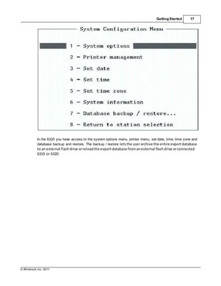
Getting Started 15
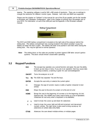
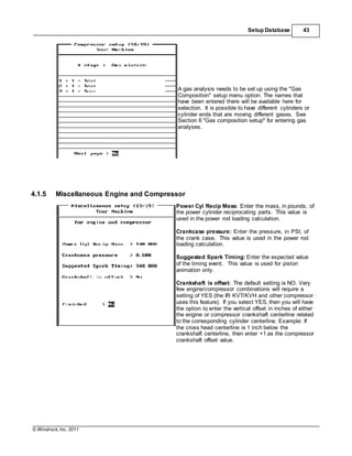
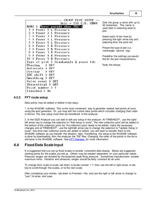
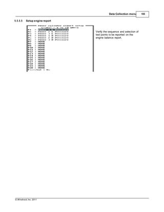
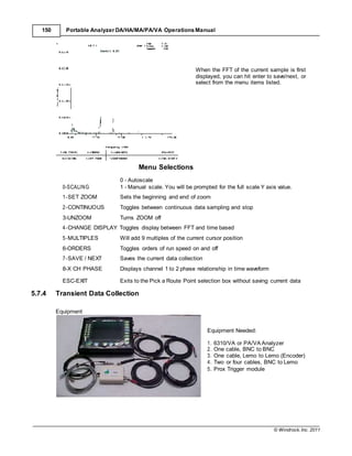
Screen width Typically set to 40 column
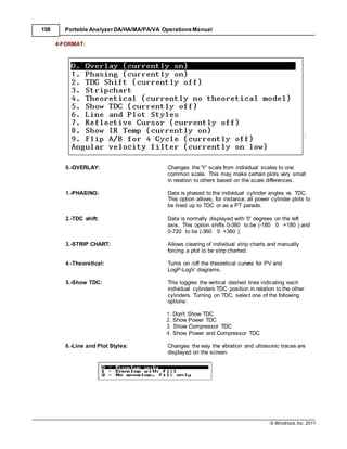
Text Cursor Style The style of the cursor may be changed between ARROW, BAR,
or BOX
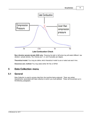
Enable run numbers: This allows the collection of data using run numbers. A run is an
individual set of data collected in sequence on the same day. By
assigning a run number, the data sets are then separated and
recalled for reporting individually. If this option is turned on, the
user will be prompted to enter a run number at the time the data is
collected. Run numbers start with 1 and can be incremented at any
time by the user. If one hour has passed without collecting data,
the user will be prompted "Do you want to change run number?".
At that time, you may continue with the same run number or
change it if needed
Start load steps with: "Load steps" are a control mechanism for many compressors and
each load step has clearance data associated with it. In the
"Compressor Setup" section, a load step table is used to hold this
clearance data. This option, to start with ZERO, ONE, or a
LETTER for the load step increment, should be set prior to doing
compressor setups.
Load steps in: Clearance data for each end of a cylinder is entered in the
"Compressor Setup" section. The clearance may be entered in
either "Percent clearance" (percent of swept volume) or "Cubic
inches".
Autoscan first in take data: This option controls how the data collection process runs. '
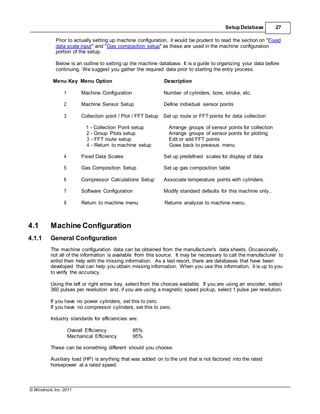
Autoscan first in take data' has four options.
1. When set to yes, entering the data collection process will
automatically start the analyzer auto scanning data and updating
the screen with each collection of data until the 3 key [STOP
AUTOSCAN] is pressed.
2. 'Yes auto save' If this is selected during take data, the last
single scan of auto scanning will be saved before taking the
normal data without asking if you want it saved.
3. 'Yes no save' will not save the last single autoscan and proceed
to taking normal data without asking.
4. 'No' turns off "Autoscan"
Use unit conversion: NO uses the default standard units that have always been
available. Setting to YES will allow selecting from different
conversion groups (see "Unit group" below).
Unit group: Allows selecting either Standard or Metric Units. If you have added
additional custom groups in the Win63X0PA software and
downloaded them to the analyzer, those custom groups will also be
available for selection.
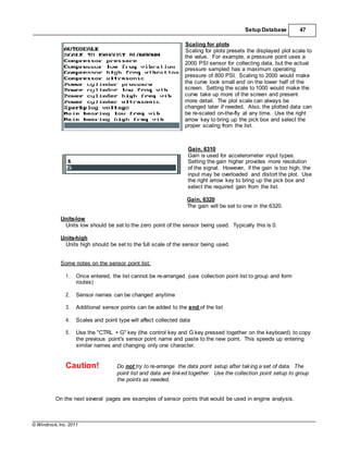
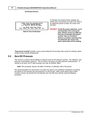
DC Sensor correction: Allows you to select from three choices.
1. "Zero Only" allows you to reference the zero pressure to the
current atmospheric pressure.
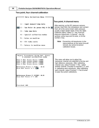
2. "Two Point one channel" allows you to provide known pressures
for calibration, one channel at a time.
3. "Two Point four channel" allows you to provide known pressures
for calibration, four channels at a time.](https://image.slidesharecdn.com/63x0-manualwindrock-140716231104-phpapp02/85/63-x0-manual-windrock-23-320.jpg)


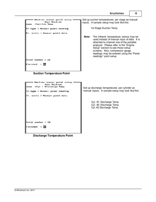
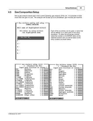
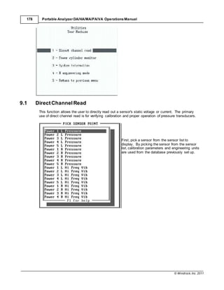
![© Windrock, Inc. 2011
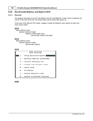
74 Portable Analyzer DA/HA/MA/PA/VA Operations Manual
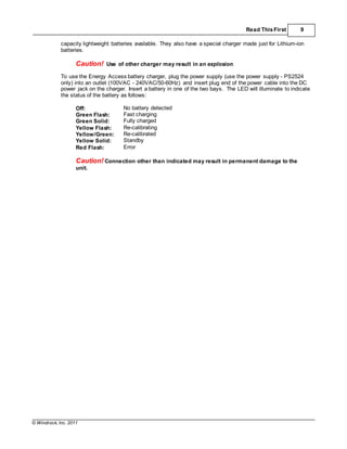
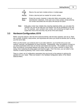
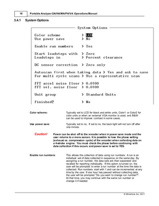
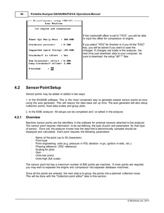
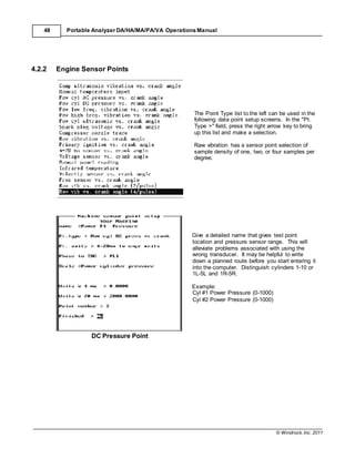
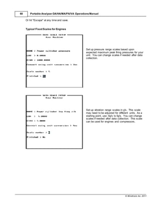
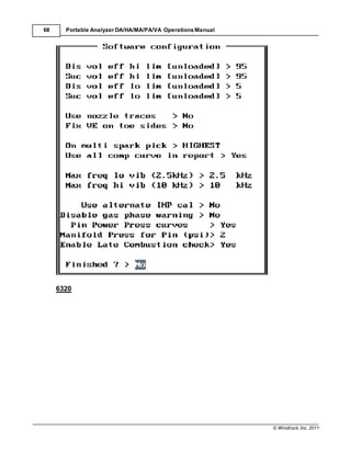
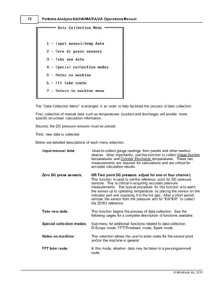
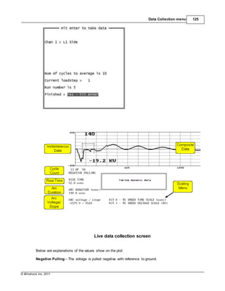
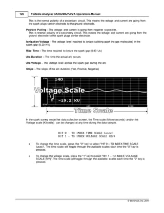
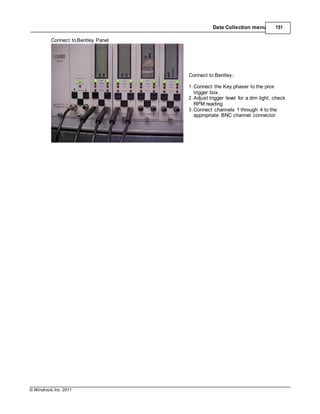
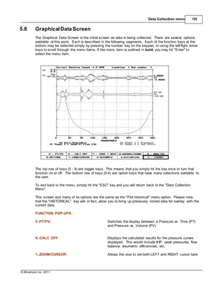
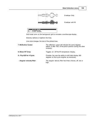
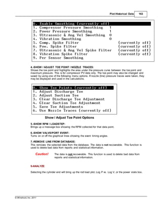
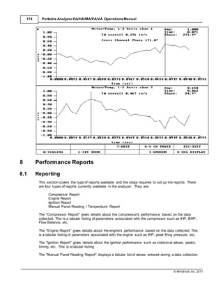
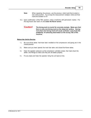
Data Entry Screen
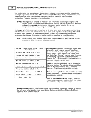
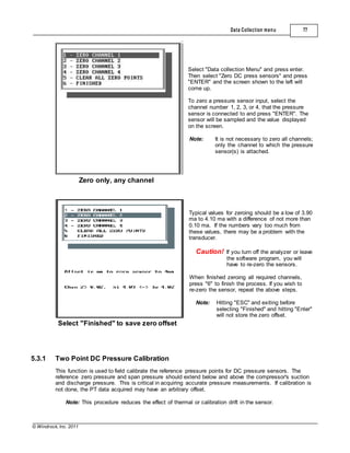
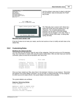
A screen appears (as shown on the left)
updating continuously with the measured
temperature. The following information is listed:
The channel number being used, the sensor
point name, the current reading, and the current
mode.
The mode line shows the current mode of the screen updating process. There are several modes
which can be used for various purposes. Below is a listing and the function key explanations. The
default is [7 - Save/Next] to facilitate ease of use and reduce key strokes. Simply hit the enter key to
save and move to the next point.
Key
0
Function
Single Scan
Description
Updates the screen one time per hit of the key
1 Continuous Updates the screen continuously
2 Peak Scan Updates the screen if the new value exceeds the previous
value
3 Low SCAN Updates the screen if the new values is less than the previous
value.
4 Exit Exits the "Manual/Temperature" menu
5 Run/Hold Stops the screen update temporarily
6 New Run # Allows changing of run number
7 Save/Next Allows selection of a different sensor point after saving the
current data point
8 New Date/Time Allows changing of date and time stamp for the current and
succeeding data sample. This new date and time will be used
until another menu is selected or until the date and time is
manually updated.
9 Manual Input Allows an override of the measured value by entering a value
from the keypad.](https://image.slidesharecdn.com/63x0-manualwindrock-140716231104-phpapp02/85/63-x0-manual-windrock-82-320.jpg)
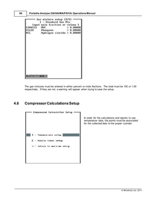
![© Windrock, Inc. 2011
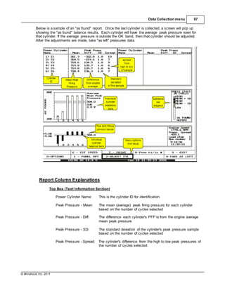
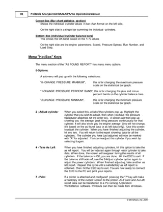
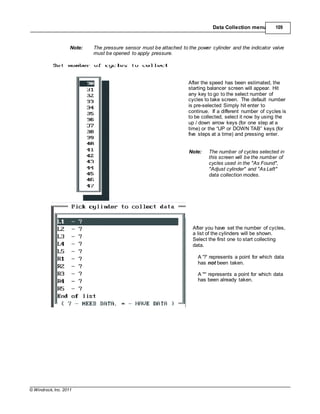
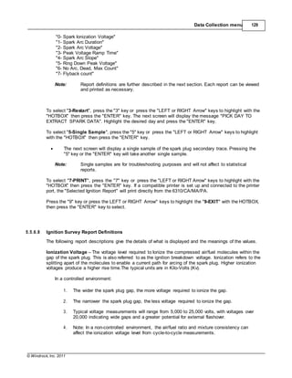
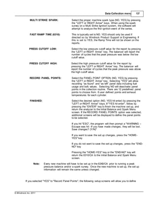
Data Collection menu 83
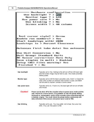
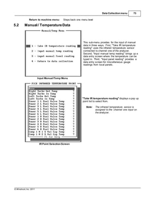
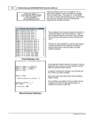
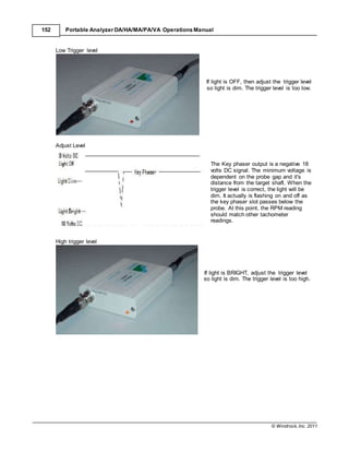
Caution! Be careful that the proper run number is assigned to the data being
collected. If the run number is changed by mistake, the data collected
will not be grouped together for reporting and will result in data being
split between run numbers. The same is true for the load step.
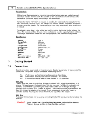
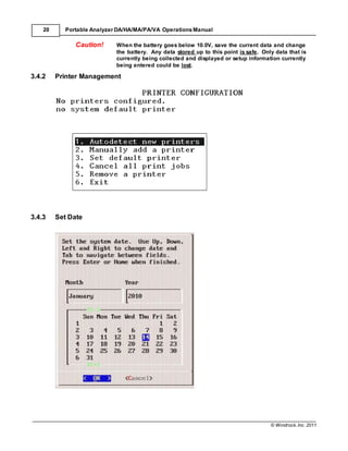
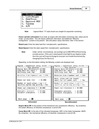
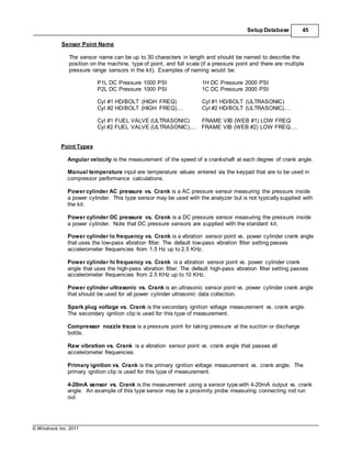
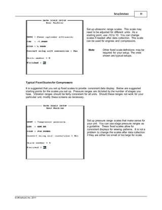
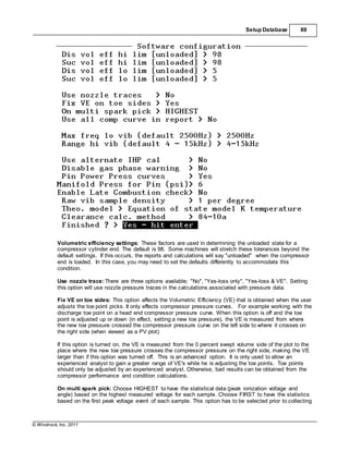
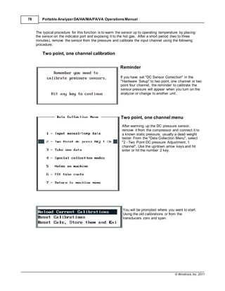
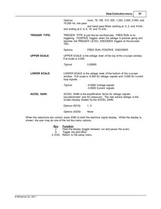
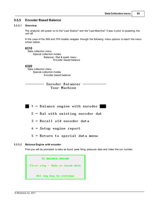
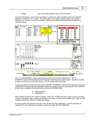
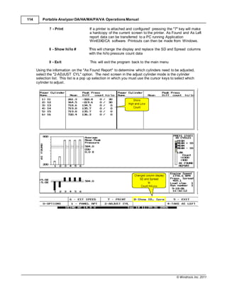
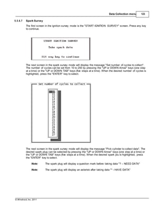
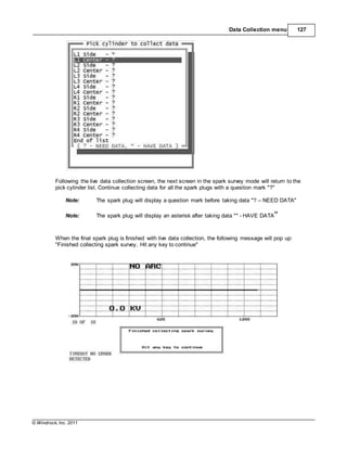
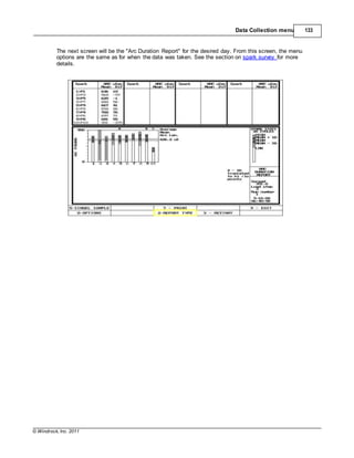
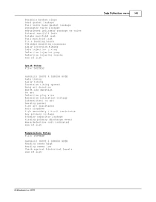
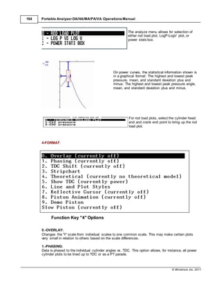
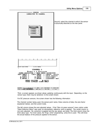
Hitting "END" and pressing "ENTER" will start the acquisition of data.
If there are signal errors from the encoder or
once-per-turn input, they will be shown at this point.
Also, if the number of averages is set high and you
are collecting data on a slow speed machine, there
may be a long delay at this point before graphics are
displayed.
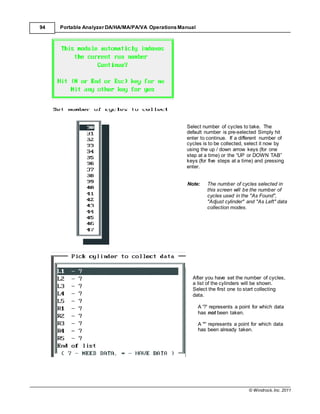
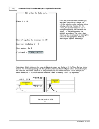
The sampled speed is checked against the entered speed value in the Machine Configuration. If the
sampled speed is less than 75% or greater than 125%, a warning message box will appear to let you
know there may be a problem. Either check the setup and connections or press the "HOME" or "Yes"
key to continue.
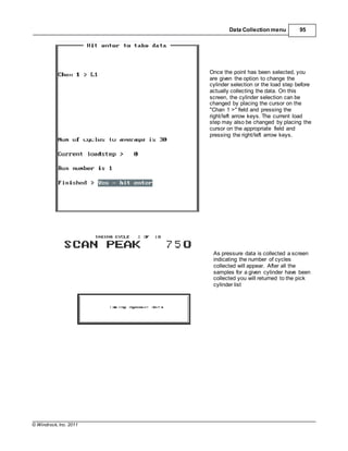
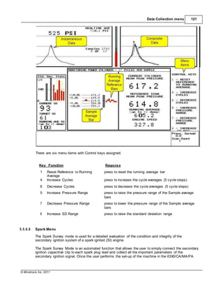
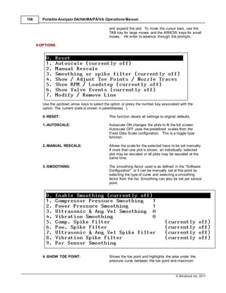
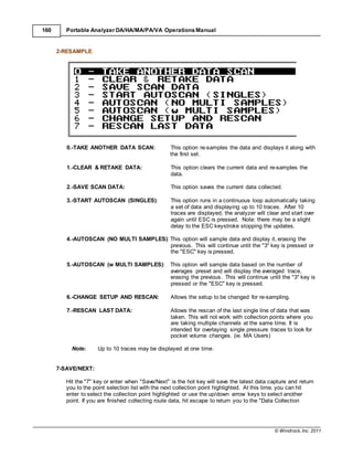
Once the data acquisition has been completed, a graphical screen will appear. At this point, you may
manipulate the data as needed.
Remember, if the option for "Autoscan in take data" is enabled, this option controls how the data
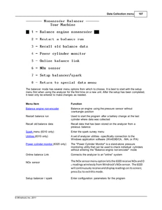
collection process runs. When set to yes, entering the data collection process will automatically start
the analyzer auto scanning data and updating the screen with each collection of data until the 3 key
[STOP AUTOSCAN] is pressed. Once the autoscan is stopped, the user is prompted to save the
latest data capture.
NOTE: Prior to saving data, you should review what is presented on the analyzer screen for
obvious problems such as a transducer connected to the wrong channel or any problem
that would give you a flat line in place of good data.
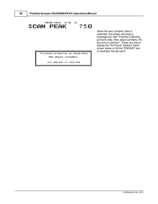
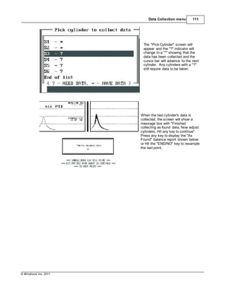
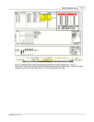
The data collection process then continues to collect the statistical data and display it, at which time
you will be able to evaluate and save the latest data capture. Hitting the "7" key or enter when
"Save/Next" is the hot key, will save the latest data capture and return you to the point selection list,
with the next collection point highlighted. At this time, you can hit enter to select the collection point
highlighted or use the up/down arrow keys to select another point. If you are finished collecting route
data, hit escape to return you to the "Data Collection Menu".
In the next section, the Graphical Data Screen functions and options will be discussed in more detail.](https://image.slidesharecdn.com/63x0-manualwindrock-140716231104-phpapp02/85/63-x0-manual-windrock-91-320.jpg)

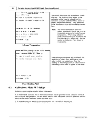
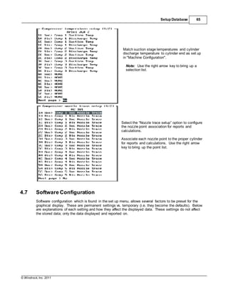
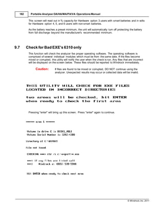
![© Windrock, Inc. 2011
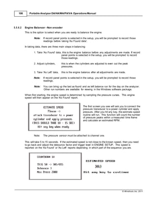
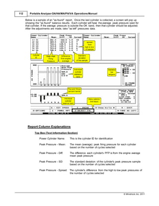
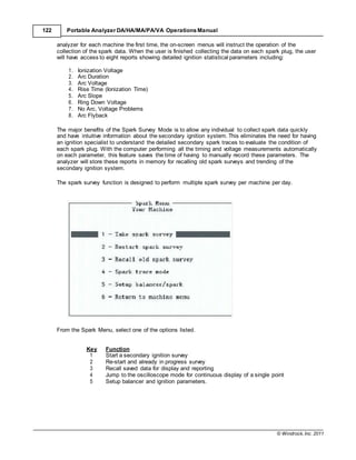
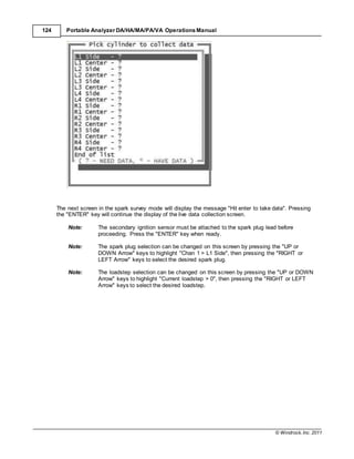
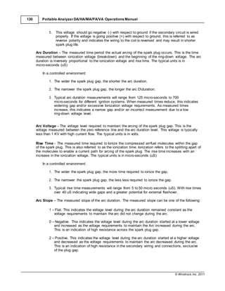
180 Portable Analyzer DA/HA/MA/PA/VA Operations Manual
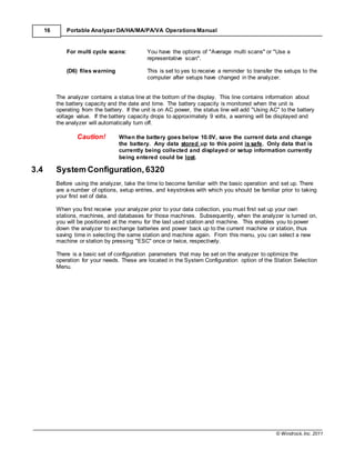
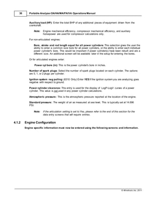
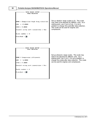
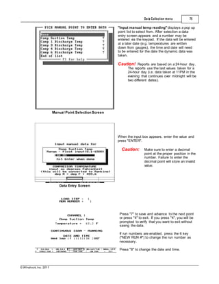
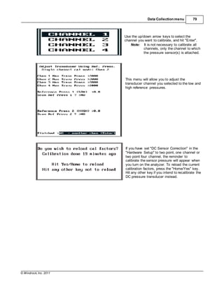
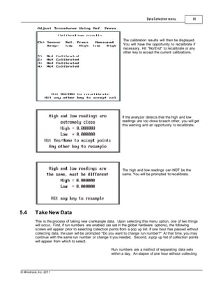
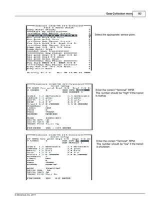
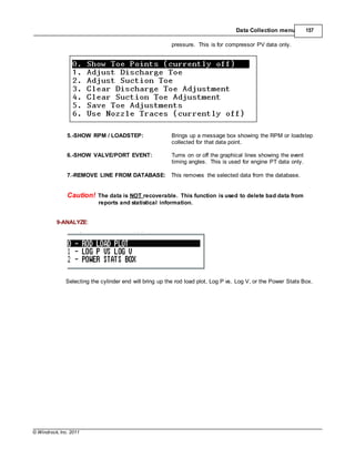
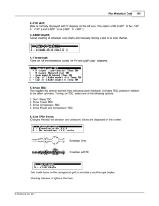
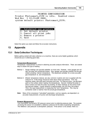
The additional three lines are used by Windrock in calibration of the analyzer and other types of
sensors.
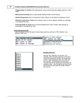
The Zero Factor line shows the bit count of the correction applied when the sensor was zeroed. Bit
count is a digital electronics value.
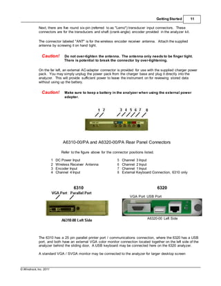
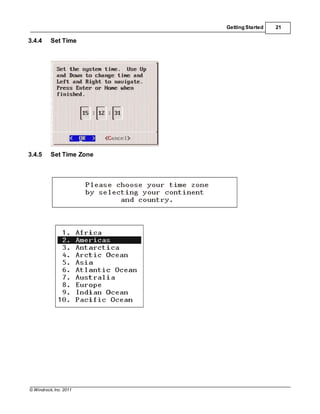
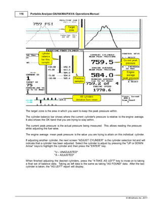
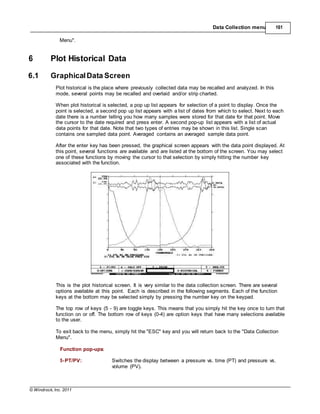
At the top of the display, a bar graph will display the current sensor value and will update based on
the mode selected. By default, the bar graph is in continuous mode. Below the bar graph is a small
bar showing the peak value reached until the [9-Reset Bar] hot key is pressed to reset the bar to
zero.
The mode line shows the current mode of the screen updating process. There are several modes
which can be used for various purposes. Below are explanations.
Key Function Description
0 Single Scan Updates the screen one time per hit of the key
1 Continuous Updates the screen continuously
2 Peak Scan Updates the screen if the new value exceeds the previous
value
3 Low Scan Updates the screen if the new value is less than the previous
value
4 Exit Exits the direct channel read function
5 Run/Hold Stops the screen update temporarily
6 1 or 4 channel
mode
Allows selection number of channels.
7 Next Allows selection of a different sensor point
8 Bar Range Select appropriate bar range
9 Reset Bar Reset bar range
9.2 Connect to Windows 6310 only
Provides a link to Win6300 / Win63X0 Windows analysis software for the analyzer. This allows the
transfer of data and setups between the analyzer and a Windows desktop/laptop.](https://image.slidesharecdn.com/63x0-manualwindrock-140716231104-phpapp02/85/63-x0-manual-windrock-188-320.jpg)

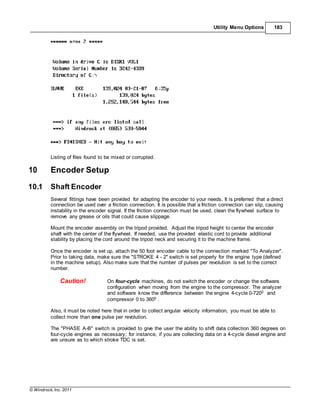
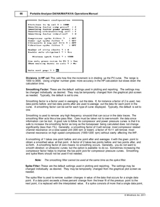
![© Windrock, Inc. 2011
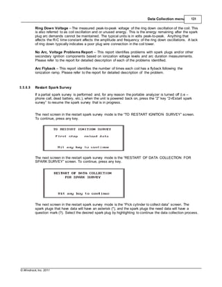
Operating System Commands 195
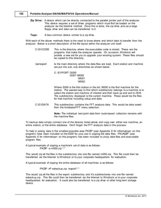
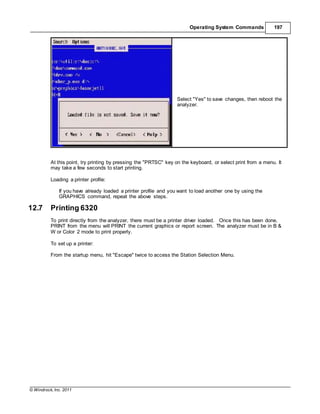
12.6 Printing 6310
To print directly from the analyzer there must be a printer driver loaded prior to running the software.
Once this has been done, select PRINT from the menu will print the current graphics or report screen.
The analyzer must be in LCD mode to print properly in black and white. You cannot use the print
function to print to a PostScript type printer.
Using the GRAPHICS command:
The GRAPHICS loads a program into upper memory that allows the analyzer to print the information
displayed on the screen. To load the GRAPHICS driver, you may do it one of two ways using the
syntax that follows. The first method requires the word GRAPHICS be typed in at the command
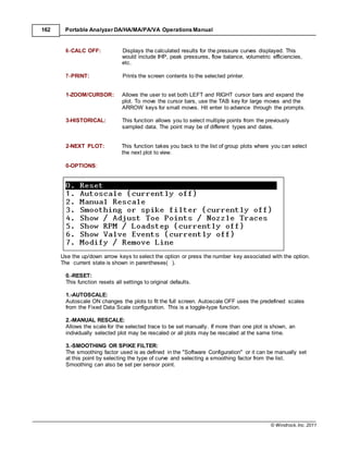
prompt. The second method requires adding the GRAPHICS command to the autoexec.bat file in
the root directory of the analyzer.
Syntax:
LOADHIGH C:DOSGRAPHICS [type] (example: LOADHIGH C:DOSGRAPHICS
LASERJETII )
type:
Specifies the type of printer. The following list shows each valid value for this parameter and
gives a brief description of its meaning:
HPDEFAULT Any Hewlett-Packard PCL printer.
DESKJET Hewlett-Packard DeskJet printer
GRAPHICS An IBM Personal Graphics Printer, IBM Proprinter, or IBM
Quietwriter printer
LASERJET A Hewlett-Packard LaserJet printer
LASERJETII A Hewlett-Packard LaserJet II printer
PAINTJET A Hewlett-Packard PaintJet printer
THINKJET A Hewlett-Packard ThinkJet printer
Installing the GRAPHICS command on the analyzer requires the following steps:
1. Press the "ESC" key until the "Select a station" menu is reached
2. Attach the small keyboard to the analyzer
3. Press the "6" key to exit to DOS
4. Type CD C: and press the "Enter" key
5. Type EDIT AUTOEXEC.BAT and press the "Enter" key
6. Press the "Down Arrow" key until the M_P line is highlighted and press the "Enter" key
7. Press the "Up Arrow" key to the blank line
8. Type LOADHIGH C:DOSGRAPHICS LASERJETII (or the type from the above list) and press
the "Enter" key
9. Type mode LPT1 RETRY=R
10. Press and hold the "ALT" and "F" keys together, then "ALT" and "X" and select "Save and exit",
press the "Enter" key to return to the DOS prompt
11. Turn the analyzer off then on or press the "CTRL" + "ALT" + "DEL" keys to reboot the analyzer](https://image.slidesharecdn.com/63x0-manualwindrock-140716231104-phpapp02/85/63-x0-manual-windrock-203-320.jpg)
![© Windrock, Inc. 2011
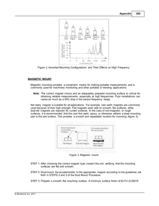
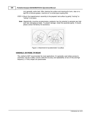
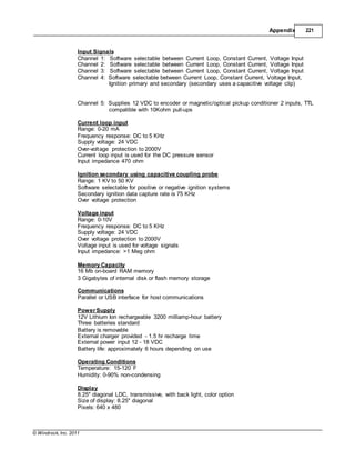
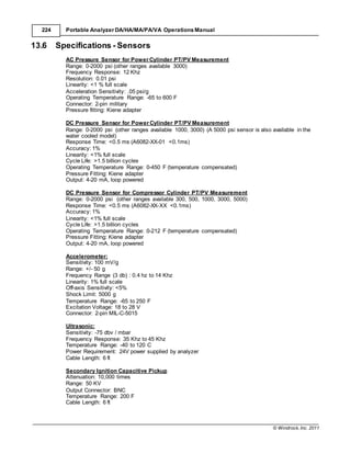
Appendix 225
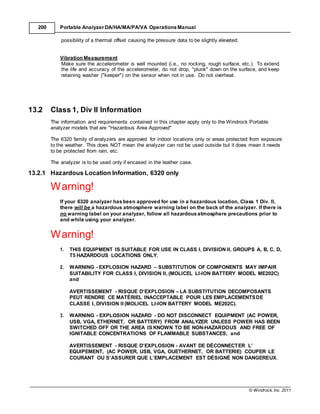
13.7 Specifications - Wireless Transmitter
Electrical
Frequency: 928.0 MHz ±25KHz
Power: 36mW
Voltage: Transmitter 12VDC Ni-MH rechargeable 3500 mA-hr battery
Receiver Power from Analyzer
Antenna
VSWR: <1.3
Type: 1/4 Wave Omnidirectional
Environmental
Weight: Transmitter 1 lb
Operating Conditions
Temperature: 150F - 1200F
Humidity: 0-90% non-condensing
INFORMATION TO USER
This device complies with Part 15 of the FCC Rules. Operation is subject to the following two
conditions: (1) This device may not cause harmful interference, and (2) This device must accept any
interference received, including interference that may cause undesired operation.
This equipment has been tested and found to comply with the limits for Class B Digital Device,
pursuant to Part 15 of the FCC Rules. These limits are designed to provide reasonable protection
against harmful interference in a residential installation. This equipment generates and can radiate
radio frequency energy and, if not installed and used in accordance with the instructions, may cause
harmful interference to radio communications. However, there is no guarantee that interference will not
occur in a particular installation. If this equipment does cause harmful interference to radio or television
reception, which can be determined by turning the equipment off and on, the user is encouraged to try
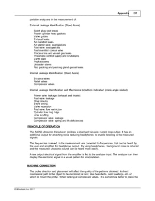
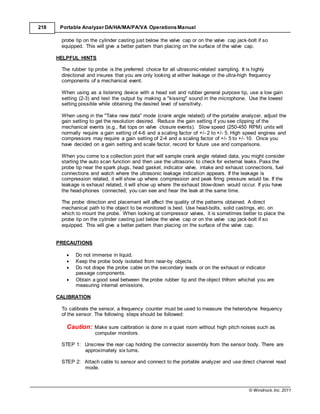
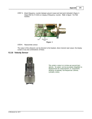
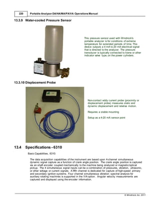
to correct the interference by one or more of the following measures:
• Reorient or relocate the receiving antenna
• Increase the separation between the equipment and receiver
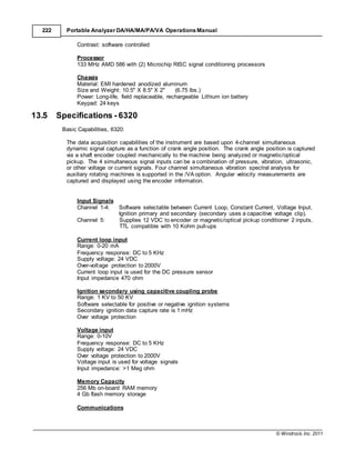
Connect the equipment into an outlet on a circuit different from that to which the receiver is
connected
• Consult the dealer or an experienced radio / TV technician for help
Any changes or modifications not expressly approved by the party responsible for compliance could
void the user’s authority to operate the equipment.
This device has been designed to operate with the antennas supplied by Windrock. Antennas not
supplied by Windrock are strictly prohibited for use with this device. The required antenna impedance
is 50 ohms.
13.8 PKZIP 6310 only
PKZIP (R) FAST! Create/Update Utility Version 2.04g 02-01-93
Copr. 1989-1993 PKWARE Inc. All Rights Reserved. Registered Version
PKZIP Reg. U.S. Pat. and Tm. Off. Patent No. 5,051,745
PKZIP /h[1] for basic help PKZIP /h[2|3|4] for other help screens.
Usage: PKZIP [options] zipfile [@list] [files...]](https://image.slidesharecdn.com/63x0-manualwindrock-140716231104-phpapp02/85/63-x0-manual-windrock-233-320.jpg)
![© Windrock, Inc. 2011
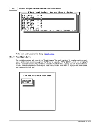
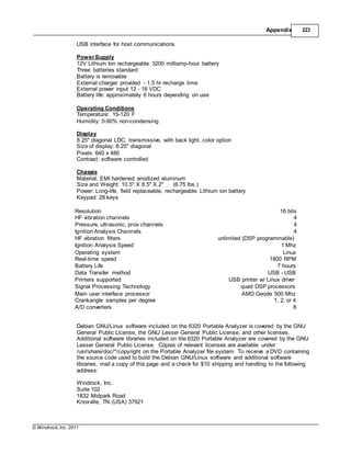
226 Portable Analyzer DA/HA/MA/PA/VA Operations Manual
-a Add files
-b[drive] create temp zipfile on alternative drive
-d Delete files
-e[x,n,f,s,0] use [eXtra|Normal (default)|Fast|Super fast|NO compression]
-f Freshen files
-l Display software License agreement
-m[f,u] Move files [with Freshen | with Update]
-u Update files
-p|P store Pathnames|p=recursed into|P=specified & recursed into
-r Recurse subdirectories
-s[pwd] Scramble with password [If no pwd is given, prompt for pwd]
-v[b][r][m][t][c] View .ZIP [Brief][Reverse][More][Technical][Comment] sort by [d,e,n,o,p,s]
[Date|Extension|N ame|natural Order(default)|Percentage|Size]
-&[f|l|u|ul|w|v][s[
drive]
Span disks [Format|format Low density|Unconditional format|
This is a registered version of PKZIP and is only for use on those machine(s) that it is licensed for.
This version is NOT TO BE DISTRIBUTED as Shareware.
PKWARE, Inc
9025 N. Deerwood Drive
Brown Deer, WI 53223
PKUNZIP (R) FAST! Extract Utility Version 2.04g 02-01-93
Copr. 1989-1993 PKWARE Inc. All Rights Reserved. Registered version
PKUNZIP Reg. U.S. Pat. and Tm. Off.
Usage: PKUNZIP [options] zipfile [@list] [files...]
-c[m] extract files to Console [with More]
-d restore/create Directory structure stored in .ZIP file
-e[c|d|e|n|p|r|s] Extract files. Sort by [CRC | Date | Extension | Name | Percentage | Reverse |
Size]
-f Freshen files in destination directory
-j|J<h,r,s> mask|don't mask <Hidden/System/Readonly> files (def.=jhrs)
-n extract only Newer files
-o Overwrite previously existing files
-p[a/b][c][#] extract to Printer [Asc mode,Bin mode,Com port] [port #]
-q Enable ANSI comments
-s[pwd] Decrypt with password [If no pwd is given, prompt for pwd]
-t Test .ZIP file integrity
-v[b][r][m][t] View .ZIP [Brief][Reverse][More][Technical] sort by [CRC| [c,d,e,n,o,p,s]
Date|Extension|Nam e|natural Order(default)|Perce ntage|Size]
-x<filespec> eXclude file(s) from extraction
-$ Restore volume label on destination drive
-@listfile Generate list file
This is a registered version of PKUNZIP and is only for use on those machine(s) that it is licensed for.
This version is NOT TO BE DISTRIBUTED as Shareware.
PKWARE, Inc
9025 N. Deerwood Drive
Brown Deer, WI 53223](https://image.slidesharecdn.com/63x0-manualwindrock-140716231104-phpapp02/85/63-x0-manual-windrock-234-320.jpg)