3M Scotchcast Flexible & Trailing Power Cable Splice Kits 82-F
•
0 likes•1,848 views

3M Scotchcast Flexible & Trailing Power Cable Splice Kits 82-F

Recommended
Recommended
More Related Content
What's hot
What's hot (20)
Viewers also liked
Viewers also liked (18)
Similar to 3M Scotchcast Flexible & Trailing Power Cable Splice Kits 82-F
Similar to 3M Scotchcast Flexible & Trailing Power Cable Splice Kits 82-F (20)
More from Thorne & Derrick International
More from Thorne & Derrick International (20)
Recently uploaded
Recently uploaded (20)
3M Scotchcast Flexible & Trailing Power Cable Splice Kits 82-F
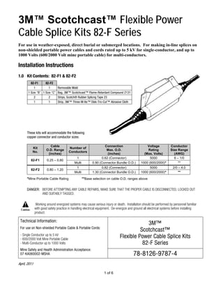
- 1. 3M™ Scotchcast™ Flexible Power Cable Splice Kits 82-F Series For use in weather-exposed, direct burial or submerged locations. For making in-line splices on non-shielded portable power cables and cords rated up to 5 kV for single-conductor, and up to 1000 Volts (600/2000 Volt mine portable cable) for multi-conductors. Installation Instructions 1.0 Kit Contents: 82-F1 & 82-F2 82-F1 82-F2 1 1 Removable Mold 1 Size “B” 1 Size “C” Bag, 3M™ Scotchcast™ Flame-Retardant Compound 2131 2 2 Strips, Scotch® Rubber Splicng Tape 23 1 1 Strip, 3M™ Three-M-Ite™ Elek-Tro-Cut™ Abrasive Cloth 1 of 6 These kits will accommodate the following copper connector and conductor sizes: Kit No. Cable O.D. Range (inches) Number of Conductors Connection Max. O.D. (inches) Voltage Rating (Max. Volts) Conductor Size Range (AWG) 1 0.62 (Connector) 5000 6 – 1/0 82-F1 0.25 – 0.80 Multi 0.90 (Connector Bundle O.D.) 1000 (600/2000)* ** 1 0.82 (Connector) 5000 2/0 – 4.0 82-F2 0.80 – 1.20 Multi 1.30 (Connector Bundle O.D.) 1000 (600/2000)* ** *Mine Portable Cable Rating **Base selection on cable O.D. ranges above DANGER: BEFORE ATTEMPTING ANY CABLE REPAIRS, MAKE SURE THAT THE PROPER CABLE IS DISCONNECTED, LOCKED OUT AND SUITABLY TAGGED. Working around energized systems may cause serious injury or death. Installation should be performed by personnel familiar with good safety practice in handling electrical equipment. De-energize and ground all electrical systems before installing product. 3M™ Scotchcast™ Flexible Power Cable Splice Kits 82-F Series Technical Information: For use on Non-shielded Portable Cable & Portable Cords: - Single Conductor up to 5 kV - 600/2000 Volt Mine Portable Cable - Multi-Conductor up to 1000 Volts Mine Safety and Health Administration Acceptance: 07-KA060002-MSHA 78-8126-9787-4 April, 2011
- 2. 2.0 Prepare Cables Table 1 Dimension Kit No. A B C 82-F1 3” 3” 3 ½” 82-F2 5 ½” 5” 7 ½” 2.1 Single Conductor (up to 5 kV) a. Remove conductor insulation (and jackets if applicable) for ½ connector length. (Figure 1) b. Smoothly pencil cable insulations for ¾”. (Figure 1) c. Scuff ends of insulation or jacket for Dimension “B” with coarse abrasive cloth provided. Remove all wax, dirt and dust from surface. (Table 1 and Figure 1) 2.2 Multi- Conductors (up to 1000 Volts, or 600/2000 Volts) a. Remove cable jackets for dimension “A”. (Table 1 and Figure 2) b. Taper ends of insulation/jackets for 1/4”. (Figure 2) c. Scuff ends of cable jackets for Dimension “B” with coarse abrasive cloth provided. Remove all wax, dirt and dust from jacket surface. (Table 1 and Figure 2) d. Remove cable fillers back to jacket. (Figure 2, Dimension “A”) 78-8126-9787-4 A 2 of 6
- 3. e. Cut off individual conductor ends to allow for connector staggering with a maximum splice opening of Dimension “C”. Provide for ¼” spacing between connector ends. (Table 1 and Figure 3) f. Remove conductor insulations for ½ connector length. (Figure 3) 3.0 INSTALL CONNECTOR(S) 3.1. Multi-Conductors: Phase match conductors to appropriate color codes, if applicable. 3.2 Join conductors with proper connector(s) and appropriate crimping tool and die. 4.0 INSULATE CONNECTION(S) Multi-Conductors Only 4.1 Non-insulated connectors only: Overwrap connector(s) with 4 half-lapped layers of vinyl electrical tape (e.g. Scotch® Super 33+™ Vinyl Electrical Tape) extending 1/4” onto conductor insulations. 4.2 Bundle conductors together with a band of vinyl tape wrapped around the center of the splice opening. 5.0 Install Mold 5.1 Trim tapered ends of mold with knife or diagonal cutting pliers to fit cable diameter. (Figure 4) 78-8126-9787-4 A 3 of 6
- 4. 5.2 Center mold over splice and tape into place by applying Scotch® Rubber Splicing Tape 23 (provided in kit) over the mold ends and onto the cable. (Figure 5) 5.3 Center splice within the mold by tensioning (pulling) cables from both ends. Hint: Use empty kit carton as a work stand. a. Make a straight knife slit in cover of closed carton that is slightly longer than the mold’s hinge. (Figure 6) b. Position carton beneath splice and press the mold’s hinge into the knife slit. This holds splice in position for compound pouring. (Figure 6) 78-8126-9787-4 A 4 of 6
- 5. 6.0 Pour Compound 6.1 Premix BLACK side of 3M™ Scotchcast™ Flame-Retardant Compound 2131 pouch by squeezing to a smooth consistency and uniform color. 6.2 Firmly grasp each flat side of the closed mixing pouch near the center barrier; at the same time pull sides of barrier apart and roll sides of thumbs through barrier. Break the barrier all the way across to the side seals. (Figure 7) 6.3 Alternately squeeze ends of pouch forcing compound rapidly back and forth, strip compound from corners of pouch between fingers. Mix until color is completely uniform – 30 to 40 VIGOROUS SQUEEZES. DO NOT EXCEED 1 MINUTE. (Figure 8) 6.4 Clip off a corner of pouch and immediately pour into mold. 78-8126-9787-4 A 5 of 6
- 6. 6.5 Fill mold until compound reaches a level that is within the mold’s filler spout. (Figure 9) 6.6 Allow compound to cure. Check compound in Filler Spout for curing. NOTE: Splice may be de-molded when compound is no longer tacky. Typical Cure Time: 16 – 24 hrs. @ 70ºF (21ºC) 24 – 30 hrs. @ 50ºF (10ºC) 36 hrs. @ 32ºF (0ºC) Typical De-mold Time: 1.5 hrs. @ 70ºF (21ºC) 4 hrs. @ 50ºF (10ºC) 6 – 8 hrs. @ 32ºF (0ºC) NOTE: Values are typical, not to be considered minimum or maximum. Always confirm based on tack and hardness of compound that resin is sufficiently cured. 7.0 De-mold 7.1 Remove Scotch® Rubber Splicing Tape 23 from mold ends. 7.2 Remove mold; start removal by first separating mold halves at the filler spout. 7.3 Trim off excess compound from filler spout by cutting off at base. (Figure 10) 3M, Scotchcast, Super 33+, Three-M-Ite and Elek-Tro-Cut are trademarks of 3M Company. Scotch is a registered trademark of 3M Company. Important Notice: All statements, technical information, and recommendations related to 3M’s products are based on information believed to be reliable, but the accuracy or completeness is not guaranteed. Before using this product, you must evaluate it and determine if it is suitable for your intended application. You assume all risks and liability associated with such use. Any statements related to the product, which are not contained in 3M’s current publications, or any contrary statements contained on your purchase order, shall have no force or effect unless expressly agreed upon, in writing, by an authorized officer of 3M. Warranty; Limited Remedy; Limited Liability: This product will be free from defects in material and manufacture at the time of purchase. 3M MAKES NO OTHER WARRANTIES INCLUDING, BUT NOT LIMITED TO, ANY IMPLIED WARRANTY OF MERCHANTABILITY OR FITNESS FOR A PARTICULAR PURPOSE. If this product is defective within the warranty period stated above, your exclusive remedy shall be, at 3M’s option, to replace or repair the 3M product or refund the purchase price of the 3M product. Except where prohibited by law, 3M will not be liable for any indirect, special, incidental or consequential loss or damage arising from this 3M product, regardless of the legal theory asserted. 3 Electrical Markets Division 6801 River Place Blvd. Austin, TX 78726-9000 800-245-3573 Please Recycle. Printed in USA. Fax 800-245-0329 © 3M 2011 All Rights Reserved. www.3M.com/electrical 78-8126-9787-4 A 6 of 6 WWW.CABLEJOINTS.CO.UK THORNE & DERRICK UK TEL 0044 191 490 1547 FAX 0044 477 5371 TEL 0044 117 977 4647 FAX 0044 977 5582 WWW.THORNEANDDERRICK.CO.UK