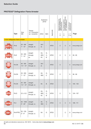
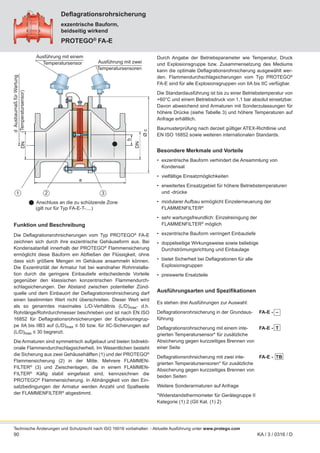
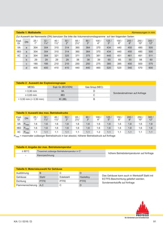
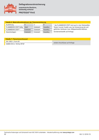
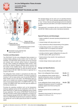
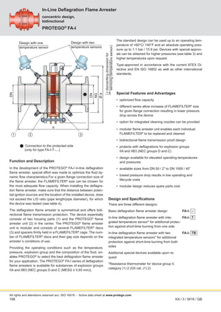
Volume 3
PROTEGO®
Deflagration Flame Arresters
for safety and environment
Volume
3
86
PROTEGO® flame arrester unit
All rights and alterations reserved acc. ISO 16016
As a component of equipment, deflagration flame arresters are
type-tested and approved along with the equipment (OEM part,
e.g. vacuum pumps, blowers). They are not available separately
as independent deflagration flame arresters.
A broad variety of types, designs, nominal diameters and materi-
als are available. In addition, we are able to develop customized
solutions for our clients at our state-of-the-art test facility, which
is the largest privately owned research center in flame arrester
business worldwide.
Special features and advantages
The devices can be distinguished and selected based on the fol-
lowing main criteria: Components for equipment (e.g. blowers,
vacuum pumps) or devices to be installed in pipelines hand-
ling gas or vapour. Special operating conditions (e.g. elevated
operatingpressuresortemperatures)thatgobeyondclassified
values of different test standards may have to be considered.
It is important to categorize the products or components into
explosion groups, depending on their MESG, to select the
suitable type of protection from the various designs.
The suitable or required approved device must be selected
from the great variety of devices that have been tested and
approved.
The basic designs of the housing are concentric, eccentric
and with a “easy access cover” for simple disassembly of the
flame arrester unit.
The system specification must be considered when choosing
the required nominal diameters and types of connection.
A heating jacket may be necessary for problematic applica-
tions.
Special designs offering unidirectional or bidirectional protec-
tion can be provided as well as versions for critical fluids (such
as products that tend to polymerize or crystallize) and spe-
cial product properties.
Deflagration arresters as specific components for OEM
equipment (e.g. blowers or vacuum pumps) are specifically
optimized and tested along with the equipment.
Preferred applications
Protection of pipelines; containers in chemical, petrochemical,
and pharmaceutical processing systems; loading systems; gas
collection systems; exhaust combustion systems; flare systems;
landfills and biogas systems and sewage treatment plants.
Deflagration Flame Arrester
Function and description
The function of flame arresters in the various combustion pro-
cesses and the location of their installation is discussed in
“Technical Fundamentals” (see Vol. 1). In this chapter, we pres-
ent PROTEGO®
in-line deflagration flame arresters which
are installed in pipelines and as components on equipment
(e.g. blowers, vacuum pumps).
With the goal of protecting process units PROTEGO®
defla-
gration flame arresters are state-of-the-art safety devices that
are used in systems handling explosive mixtures to mitigate
deflagrations. They reliably suppress the effect of a deflagration
in the pipelines near a potential ignition source, extinguish the
flame, and protect systems that cannot withstand the pressure
of an explosion. In cases where a stable flame can continue on
the flame arrester element, in-line deflagration flame arresters
only provide protection for a limited time. If this time can be ex-
ceeded, an additional measure has to be provided for mixtures
that continue to flow continuously.
The main component is the PROTEGO®
flame arrester unit (1),
which takes the energy from the deflagration and extinguishes
the flame in narrow gaps. The flame arrester unit is modular,
consisting of several FLAMEFILTER®
discs (2) installed within
the FLAMEFILTER®
cage (3). The number of FLAMEFILTER®
discs and their gap size depend on the devices intended use
and depend on process parameters such as temperature, pres-
sure, vapour group of the handled gases.
Deflagration flame arresters in pipelines for protection of pro-
cess units can only be used if approved for such application.
The distance from the potential ignition source is limited and
is expressed by (L/D)max for the individual device. A fire may
result on the flame arrester unit if the mixture continues to flow.
As the deflagration flame arrester is only approved for a spe-
cific time period, the device should be equipped with a tempera-
ture sensor to detect temperature increase caused by a flame.
Should the temperature increase over a certain level, a suitable
measure such as nitrogen purging should be used.
KA / 3 / 0117 / GB
- Active data sheet at www.protego.com
87
pressure
drop
∆p
(mbar)
flow rate V
.
(m³/h)
airflow in thousands of CFH
pressure
drop
∆p
–
inch
W.C.
Installation and servicing
PROTEGO®
deflagration flame arresters are preferably installed
as close as possible to the potential ignition source. Typically
any orientation of installation can be chosen, but the direction of
flow needs to be taken into account for designs with tempera-
ture sensors. No pipes with a nominal diameter greater than the
nominal diameter of the device shall be connected to the defla-
gration flame arrester.
Given the modular design of the PROTEGO®
flame arrester unit,
any type of deflagration flame arrester is extremely easy to ser-
vice. For servicing reasons, the location of the flame arrester
must be planned to be very accessible; a hoist must be provided
if the flame arrester is heavy. Servicing is easy for trained per-
sonnel.
PROTEGO®
deflagration flame arresters are used in areas
subject to explosion hazards. Devices have to be selected that
match the intended use. The manufacturer‘s certificate of con-
formity provides the boundary conditions for which the device is
suitable. The user has to document proper use in accordance
with applicable safety guidelines or standards.
Selection
The following main points should be considered for choosing the
correct device for your application:
• In-line flame arrester or component on equipment
(e.g. vacuum pump or blower)
• Explosion group of gas mixture
• Standard or special operating conditions (pressure and
temperature)
Finally, the following criteria are reviewed and considered
• Nominal diameter and type of connection
• Approvals according to ATEX, Gost-R, GL, etc..
• Concentric or eccentric design or designed with an easy
access cover
• Heating jacket or heating coil
• Critical fluids
• Unidirectional or bidirectional protection
Based on this initial selection, the additional details such as ma-
terials, coatings, etc. can be requested or specified.
If no suitable device can be selected, please contact us. Special
designs and approvals are available upon request.
Sizing
The nominal diameter of the device is determined or checked
in the p/V
.
performance diagram. A safety factor must be con-
sidered when the fluid has a tendency to clog the flame arrester
element.
Given: Volume flow m3
/h or CFH
Given: Max. all. pressure drop ∆p mbar or inch W.C.
Desired: Nominal diameter of the
deflagration flame arrester DN
Procedure: Intersection of the lines with volume flow and
maximum allowable pressure drop lies above
or on the desired nominal diameter curve of
the device
Given: Volume flow m3
/h or CFH
Given: Nominal diameter of pipe DN
Desired: Pressure drop ∆pmbar or inch W.C.
Procedure: Intersection of the lines with the volume flow and
nominal diameter curve of the device, horizontal
straight line leads to the desired flow resistance
Instructions on calculating the volume flow or influence of den-
sity are found in Technical Fundamentals (Vol. 1).
After all the steps are complete, the device can be specified and
ordered.
For special cases, please fill out the questionnaire with the pro-
cess data in Vol. 1, that will serve as information for providing
a quote.
KA / 3 / 0117 / GB
for safety and environment
88
All rights and alterations reserved acc. ISO 16016
Selection Guide
PROTEGO®
Deflagration Flame Arrester
KA / 3 / 0117 / GB
Explosion-
group
Special
designs
for
higher
temperatures
and
pressures
for
critical
medium
(polimerisation,
corrosi-
on,
crystallisation)
unidirectional
bidirectional
Approvals
Type
Size
DN
Design
cc = concentric
ec = eccentric ATEX NEC Page

=

=

=
X
=
In-line deflagration flame arrester
FA-E
25 - 300
1" - 12"
straight
through, ec
IIA1
(I)
- ATEX   X www.protego.com
FA-E
25 - 300
1" - 12"
straight
through,
ec
IIA,
IIB3,
IIC
D,
C,
B
ATEX   X 90 - 95
FA-CN
40 - 300
1½" - 12"
straight
through, cc
IIA1
(I)
- ATEX  X www.protego.com
FA-CN
25 - 300
1" - 12"
straight
through, cc
IIA,
IIB3
D,
C
ATEX  X 96 - 99
FA-CN
40 - 300
1½" - 12"
straight
through, cc
IIC B ATEX X 100 - 102
FA-G G ½ - G 2
straight
through, cc
IIA,
IIB3,
IIC
D,
C,
B
ATEX  X 104 - 107
FA-I
50 - 1000
2" - 40"
straight
through, cc
IIA,
IIB3
D,
C
ATEX   X 108 - 111
FA-I-PTFE
50 - 150
2" - 6"
straight
through, cc
IIA D ATEX  X www.protego.com
- Active data sheet at www.protego.com
89
Notes:
for safety and environment
90
exzentrische Bauform,
beidseitig wirkend
Deflagrationsrohrsicherung
PROTEGO®
FA-E
Technische Änderungen und Schutzrecht nach ISO 16016 vorbehalten
Funktion und Beschreibung
Die Deflagrationsrohrsicherungen vom Typ PROTEGO®
FA-E
zeichnen sich durch ihre exzentrische Gehäuseform aus. Bei
Kondensatanfall innerhalb der PROTEGO®
Flammensicherung
ermöglicht diese Bauform ein Abfließen der Flüssigkeit, ohne
dass sich größere Mengen im Gehäuse ansammeln können.
Die Exzentrizität der Armatur hat bei wandnaher Rohrinstalla-
tion durch die geringere Einbautiefe entscheidende Vorteile
gegenüber den klassischen konzentrischen Flammendurch-
schlagsicherungen. Der Abstand zwischen potentieller Zünd-
quelle und dem Einbauort der Deflagrationsrohrsicherung darf
einen bestimmten Wert nicht überschreiten. Dieser Wert wird
als so genanntes maximales L/D-Verhältnis (L/D)max
, d.h.
Rohrlänge/Rohrdurchmesser beschrieben und ist nach EN ISO
16852 für Deflagrationsrohrsicherungen der Explosionsgrup-
pe IIA bis IIB3 auf (L/D)max ≤ 50 bzw. für IIC-Sicherungen auf
(L/D)max ≤ 30 begrenzt.
Die Armaturen sind symmetrisch aufgebaut und bieten bidirekti-
onale Flammendurchschlagsicherheit. Im Wesentlichen besteht
die Sicherung aus zwei Gehäusehälften (1) und der PROTEGO®
Flammensicherung (2) in der Mitte. Mehrere FLAMMEN-
FILTER®
(3) und Zwischenlagen, die in einem FLAMMEN-
FILTER®
Käfig stabil eingefasst sind, kennzeichnen die
PROTEGO®
Flammensicherung. In Abhängigkeit von den Ein-
satzbedingungen der Armatur werden Anzahl und Spaltweite
der FLAMMENFILTER®
abgestimmt.
Durch Angabe der Betriebsparameter wie Temperatur, Druck
und Explosionsgruppe bzw. Zusammensetzung des Mediums
kann die optimale Deflagrationsrohrsicherung ausgewählt wer-
den. Flammendurchschlagsicherungen vom Typ PROTEGO®
FA-E sind für alle Explosionsgruppen von IIA bis IIC verfügbar.
Die Standardausführung ist bis zu einer Betriebstemperatur von
+60°C und einem Betriebsdruck von 1,1 bar absolut einsetzbar.
Davon abweichend sind Armaturen mit Sonderzulassungen für
höhere Drücke (siehe Tabelle 3) und höhere Temperaturen auf
Anfrage erhältlich.
Baumusterprüfung nach derzeit gültiger ATEX-Richtlinie und
EN ISO 16852 sowie weiteren internationalen Standards.
Besondere Merkmale und Vorteile
• exzentrische Bauform verhindert die Ansammlung von
Kondensat
• vielfältige Einsatzmöglichkeiten
• erweitertes Einsatzgebiet für höhere Betriebstemperaturen
und -drücke
• modularer Aufbau ermöglicht Einzelerneuerung der
FLAMMENFILTER®
• sehr wartungsfreundlich: Einzelreinigung der
FLAMMENFILTER®
möglich
• exzentrische Bauform verringert Einbautiefe
• doppelseitige Wirkungsweise sowie beliebige
Durchströmungsrichtung und Einbaulage
• bietet Sicherheit bei Deflagrationen für alle
Explosionsgruppen
• preiswerte Ersatzteile
Ausführungsarten und Spezifikationen
Es stehen drei Ausführungen zur Auswahl:
Deflagrationsrohrsicherung in der Grundaus-
führung
Deflagrationsrohrsicherung mit einem inte-
grierten Temperatursensor* für zusätzliche
Absicherung gegen kurzzeitiges Brennen von
einer Seite
Deflagrationsrohrsicherung mit zwei inte-
grierten Temperatursensoren* für zusätzliche
Absicherung gegen kurzzeitiges Brennen von
beiden Seiten
Weitere Sonderarmaturen auf Anfrage
*Widerstandsthermometer für Gerätegruppe II
Kategorie (1) 2 (GII Kat. (1) 2)
FA-E - –
FA-E - T
FA-E - TB
 Anschluss an die zu schützende Zone
(gilt nur für Typ FA-E-T-....)
d
Ausbaumaß
für
Wartung
(Temperatursensor)
KA / 3 / 0316 / D
Ausführung mit einem
Temperatursensor Ausführung mit zwei
Temperatursensoren
g
(T
(
(
(
emperatursensor)

DN
DN
Ø
c
b
a
- Aktuelle Ausführung unter www.protego.com
1 2 3
91
für Sicherheit und Umweltschutz
Tabelle 1: Maßtabelle Abmessungen in mm
Zur Auswahl der Nennweite (DN) benutzen Sie bitte die Volumenstromdiagramme auf den folgenden Seiten
Expl.
Gr.
DN
25 /
1"
32 /
1¼"
40 /
1½"
50 /
2"
65 /
2½"
80 /
3"
100 /
4"
125 /
5"
150 /
6"
200 /
8"
250 /
10"
300 /
12"
IIA a 304 304 310 314 360 364 370 434 440 450 480 500
IIB3 a 304 304 310 314 360 364 370 434 440 450 480 500
IIC a 304 304 321 325 371 375 381 445 451 461 491 511
b 29 29 29 29 38 38 39 65 65 55 58 60
c 185 185 210 210 250 250 275 385 385 450 500 575
d 400 400 410 410 440 440 460 520 520 540 570 600
Tabelle 2: Auswahl der Explosionsgruppe
MESG Expl. Gr. (IEC/CEN) Gas Group (NEC)
Sonderabnahmen auf Anfrage
> 0,90 mm IIA D
≥ 0,65 mm IIB3 C
< 0,50 mm (> 0,50 mm) IIC (IIB) B
Tabelle 3: Auswahl des max. Betriebsdrucks
Expl.
Gr.
DN
25 /
1"
32 /
1¼"
40 /
1½"
50 /
2"
65 /
2½"
80 /
3"
100 /
4"
125 /
5"
150 /
6"
200 /
8"
250 /
10"
300 /
12"
IIA Pmax 1,6 1,6 1,6 1,6 1,6 1,6 1,6 1,6 1,6 1,6 1,6 1,6
IIB3 Pmax 1,6 1,6 1,6 1,6 1,6 1,6 1,6 1,6 1,6 1,6 1,6 1,6
IIC Pmax 1,1 1,1 1,1 1,1 1,1 1,1 1,2 1,1 1,1 1,1 1,1 1,1
Pmax = maximaler zulässiger Betriebsdruck in bar absolut, höherer Betriebsdruck auf Anfrage
Tabelle 4: Angabe der max. Betriebstemperatur
≤ 60°C Tmaximal zulässige Betriebstemperatur in C°
höhere Betriebstemperaturen auf Anfrage
- Kennzeichnung
Tabelle 5: Materialauswahl für Gehäuse
Ausführung B C D
Das Gehäuse kann auch in Werkstoff Stahl mit
ECTFE-Beschichtung geliefert werden.
Sonderwerkstoffe auf Anfrage
Gehäuse Stahl Edelstahl Hastelloy
Dichtung PTFE PTFE PTFE
Flammensicherung A,C C D
KA / 3 / 0316 / D
92
Deflagrationsrohrsicherung
PROTEGO®
FA-E
Tabelle 6: Materialkombinationen der Flammensicherung
Ausführung A C D * die FLAMMENFILTER®
sind auch in den Werkstoffen
Tantal, Inconel, Kupfer usw. bei Verwendung der auf-
geführten Gehäuse- bzw. Käfigwerkstoffe lieferbar.
Sonderwerkstoffe auf Anfrage.
FLAMMENFILTER®
Käfig Stahl Edelstahl Hastelloy
FLAMMENFILTER®
* Edelstahl Edelstahl Hastelloy
Zwischenlagen Edelstahl Edelstahl Hastelloy
Tabelle 7: Flanschanschlussart
EN 1092-1; Form B1
andere Anschlüsse auf Anfrage
ASME B16.5; 150 lbs RFSF
Technische Änderungen und Schutzrecht nach ISO 16016 vorbehalten
KA / 3 / 0316 / D
exzentrische Bauform,
beidseitig wirkend
- Aktuelle Ausführung unter www.protego.com
93
Druckverlust
∆p
(mbar)
Volumenstrom V
.
(m³/h) Leistung-000279-de
Druckverlust
∆p
(mbar)
Volumenstrom V
.
(m³/h) Leistung-000251-de
airflow in thousands of CFH
pressure
drop
∆p
–
inch
W.C.
pressure
drop
∆p
–
inch
W.C.
airflow in thousands of CFH
Diese Volumenstromdiagramme sind mit einer kalibrierten und TÜV-zertifizierten Strömungsmessanlage ermittelt
worden.
Der Volumenstrom V
.
in m³/h bezieht sich auf den technischen Normzustand von Luft nach
ISO 6358 (20°C, 1bar). Umrechnung auf andere Dichte und Temperatur siehe Kap. 1: Technische Grundlagen.
Volumenstromdiagramme
Deflagrationsrohrsicherung
PROTEGO®
FA-E
für Sicherheit und Umweltschutz
KA / 3 / 0316 / D
FA-E-IIA-P1,6
FA-E-IIA-P1,2
94
Deflagrationsrohrsicherung
PROTEGO®
FA-E
Volumenstromdiagramme
Technische Änderungen und Schutzrecht nach ISO 16016 vorbehalten
Diese Volumenstromdiagramme sind mit einer kalibrierten und TÜV-zertifizierten Strömungsmessanlage ermittelt
worden.
Der Volumenstrom V
.
in m³/h bezieht sich auf den technischen Normzustand von Luft nach ISO 6358 (20°C, 1bar).
Umrechnung auf andere Dichte und Temperatur siehe Kap. 1: Technische Grundlagen.
KA / 3 / 0316 / D
- Aktuelle Ausführung unter www.protego.com
Druckverlust
∆p
(mbar)
Volumenstrom V
.
(m³/h) Leistung-000281-de
airflow in thousands of CFH
pressure
drop
∆p
–
inch
W.C.
FA-E-IIB3-P1,6
Druckverlust
∆p
(mbar)
Volumenstrom V
.
(m³/h) Leistung-000280-de
airflow in thousands of CFH
pressure
drop
∆p
–
inch
W.C.
FA-E-IIB3-P1,1
95
*
* P1,2
für Sicherheit und Umweltschutz
KA / 3 / 0316 / D
Druckverlust
∆p
(mbar)
Volumenstrom V
.
(m³/h) Leistung-000282-de
airflow in thousands of CFH
pressure
drop
∆p
–
inch
W.C.
FA-E-IIC-P1,1
96

a
DN
DN
Ø
d
b
c
All rights and alterations reserved acc. ISO 16016
concentric design,
bidirectional
In-Line Deflagration Flame Arrester
PROTEGO®
FA-CN-IIA and IIB3
Function and Description
The PROTEGO®
FA-CN in-line deflagration flame arrester is a
compact design utilizing an easy access cover for easy main-
tainability. The PROTEGO®
flame arrester unit can be removed
and cleaned within moments without having to disassemble
the pipe. When installing the deflagration flame arrester, make
sure that the distance between potential ignition sources and
the location of the installed device, does not exceed the L/D
ratio (pipe length/pipe diameter), for which the device was test-
ed. According to EN ISO 16852 this device is approved for a
(L/D)max ratio of 50.
The deflagration flame arrester is symmetrical and offers bidi-
rectional flame transmission protection. The device consists of a
housing (1) with an easy access cover (3) and the PROTEGO®
flame arrester unit (2) in the center. The PROTEGO®
flame ar-
rester unit is modular and consists of several FLAMEFILTER®
discs (3) and spacers firmly held in a FLAMEFILTER®
cage. The
number of FLAMEFILTER®
discs and their gap size depend on
the devices intended use.
Providing the operating conditions such as the temperature,
pressure, explosion group and the composition of the fluid, en-
ables PROTEGO®
to select the best deflagration flame arrester
for your application. This version of PROTEGO®
FA-CN-IIA and
IIB3 flame arrester protects against deflagrations of fuel/air mix-
tures of explosion groups IIA and IIB 3 (NEC D and C (MESG ≥
0.65 mm)). PROTEGO®
FA-CN devices for substances of explo-
sion groups IIA1 and IIC (NEC group B) are shown on separate
pages.
The standard design can be used up to an operating tempera-
ture of +60°C / 140°F and an absolute operating pressure up to
1.1 bar / 15.9 psi. Devices with special approval can be obtained
for higher pressures (see table 3) and higher temperatures upon
request.
Type-approved in accordance with the current ATEX Directive
and EN ISO 16852 as well as other international standards.
Special Features and Advantages
• design available for elevated operating temperatures and
pressures
• compact design with easy access cover
• easy maintenance without disassembling of the pipeline
• modular flame arrester unit enables individual
FLAMEFILTER®
to be replaced and cleaned
• bidirectional flame transmission proof design
• provides protection against deflagrations for group IIA
and IIB3 vapours (NEC group D and C)
• lowest pressure drop results in low operating and
lifecycle costs
• modular design reduces spare parts cost
Design and Specifications
There are three different designs:
Basic in-line deflagration flame arrester
In-line deflagration flame arrester with in-
tegrated temperature sensor* as additional
protection against short time burning from
one side
In-line deflagration flame arrester with two
integrated temperature sensors* for additional
protection against short-time burning from
both sides
Additional special devices available upon
request
*Resistance thermometer for device group II,
category (1) 2 (GII cat. (1) 2)
FA-CN - –
FA-CN - T
FA-CN - TB
 Connection to the protected side
(only for type FA-CN-T-....)
KA / 3 / 0316 / GB
Design with one
temperature sensor
Design with two
temperature sensors
each temperature sensor turned
by 90° on the drawing
- Active data sheet at www.protego.com
1 2 3 4
97
for safety and environment
Table 1: Dimensions Dimensions in mm / inches
To select the nominal size (DN), use the flow capacity charts on the following pages
DN
25 /
1"
32 /
1¼"
40 /
1½"
50 /
2"
65 /
2½"
80 /
3"
100 /
4"
125 /
5"
150 /
6"
200 /
8"
250 /
10"
300 /
12"
a
200 /
7.87
200 /
7.87
210 /
8.27
215 /
8.46
235 /
9.25
240 /
9.45
265 /
10.43
305 /
12.01
310 /
12.20
300 /
11.81
320 /
12.60
350 /
13.78
b
92 /
3.62
92 /
3.62
105 /
4.13
105 /
4.13
132 /
5.2
132 /
5.2
150 /
5.91
197 /
7.75
197 /
7.75
220 /
8.66
260 /
10.24
295 /
11.61
c
175 /
6.89
175 /
6.89
200 /
7.87
200 /
7.87
260 /
10.24
260 /
10.24
308 /
12.13
415 /
16.34
415 /
16.34
446 /
17.56
520 /
20.47
600 /
23.62
d
105 /
4.13
105 /
4.13
130 /
5.12
130 /
5.12
185 /
7.28
185 /
7.28
220 /
8.66
310 /
12.20
310 /
12.20
355 /
13.98
420 /
16.54
490 /
19.29
Table 2: Selection of the explosion group
MESG Expl. Gr. (IEC/CEN) Gas Group (NEC)
Special approvals upon request
> 0.90 mm IIA D
≥ 0.65 mm IIB3 C
Table 3: Selection of max. operating pressure
Expl.
Gr.
DN
25 /
1"
32 /
1¼"
40 /
1½"
50 /
2"
65 /
2½"
80 /
3"
100 /
4"
125 /
5"
150 /
6"
200 /
8"
250 /
10"
300 /
12"
n
IIA Pmax
1.6 /
23.2
1.6 /
23.2
1.6 /
23.2
1.6 /
23.2
1.6 /
23.2
1.6 /
23.2
1.5 /
21.8
1.5 /
21.8
1.5 /
21.8
1.3 /
18.9
1.3 /
18.9
1.3 /
18.9
3
IIB3 Pmax
1.6 /
23.2
1.6 /
23.2
1.6 /
23.2
1.6 /
23.2
1.6 /
23.2
1.6 /
23.2
1.6 /
23.2
1.6 /
23.2
1.6 /
23.2
1.6 /
23.2
1.6 /
23.2
1.6 /
23.2
3
Pmax = maximum allowable operating pressure in bar / psi absolute, higher operating pressure upon request
n = number of FLAMEFILTER®
Table 4: Specification of max. operating temperature
≤ 60°C / 140°F Tmaximum allowable operating temperature in °C
higher operating temperatures upon request
- Designation
Table 5: Material selection
Design A B
Special materials upon request
Housing Steel Stainless Steel
Cover Steel Stainless Steel
Gasket PTFE PTFE
Flame arrester unit Stainless Steel Stainless Steel
Table 6: Flange connection type
EN 1092-1; Form B1
other types upon request
ASME B16.5; 150 lbs RFSF
KA / 3 / 0316 / GB
98
All rights and alterations reserved acc. ISO 16016
Flow Capacity Charts
In-Line Deflagration Flame Arrester
PROTEGO®
FA-CN-IIA and IIB3
KA / 3 / 0316 / GB
The flow capacity charts have been determined with a calibrated and TÜV certified flow capacity test rig.
Volume flow V
.
in (m³/h) and CFH refer to the standard reference conditions of air ISO 6358 (20°C, 1bar).
Conversion to other densities and temperatures refer to Vol. 1: “Technical Fundamentals”.
- Active data sheet at www.protego.com
FA-CN-IIA-P1.2
2-fold FLAMEFILTER®
FA-CN-IIA-P*
3-fold FLAMEFILTER®
airflow in thousands of CFH
pressure
drop
∆p
–
inch
W.C.
airflow in thousands of CFH
pressure
drop
∆p
–
inch
W.C.
flow rate V
.
(m³/h) Leistung-000340-en
flow rate V
.
(m³/h) Leistung-000341-en
pressure
drop
∆p
(mbar)
pressure
drop
∆p
(mbar)
P* see table 3
99
for safety and environment
KA / 3 / 0316 / GB
pressure
drop
∆p
(mbar)
flow rate V
.
(m³/h) Leistung-000342-en
airflow in thousands of CFH
pressure
drop
∆p
–
inch
W.C.
pressure
drop
∆p
(mbar)
flow rate V
.
(m³/h) Leistung-000343-en
airflow in thousands of CFH
pressure
drop
∆p
–
inch
W.C.
FA-CN-IIB3-P1.1
2-fold FLAMEFILTER®
FA-CN-IIB3-P1.6
3-fold FLAMEFILTER®
100

a
DN
DN
Ø
d
b
c
All rights and alterations reserved acc. ISO 16016
 Connection to the protected side
(only for type FA-CN-T-....)
for hydrogen/air-mixtures, concentric design,
bidirectional
In-Line Deflagration Flame Arrester
PROTEGO®
FA-CN-IIC
Function and Description
The PROTEGO®
FA-CN in-line deflagration flame arrester is a
compact design utilizing an easy access cover for easy maintain-
ability. The special PROTEGO®
FA-CN-IIC version was devel-
oped for hydrogen applications (group IIC vapours – NEC group
B). The device is designed to have comparetively large gaps, in
relation to other flame arresters for the same explosion group.
This allows to apply it to processes having small fluid droplets or
particles. The PROTEGO®
flame arrester unit can be removed
and cleaned within moments without having to disassemble
the pipe. When installing the deflagration flame arrester, make
sure that the distance between potential ignition sources and the
location of the installed device, does not exceed the L/D ratio
(pipe length/pipe diameter), for which the device was approved
(see table 4).
The deflagration flame arrester is symmetrical and offers bidi-
rectional flame transmission protection. The device consists of a
housing (1) with an easy access cover (3) and the PROTEGO®
flame arrester unit (2) in the center. The PROTEGO®
flame ar-
rester unit is modular and consists of several FLAMEFILTER®
discs (3) and spacers firmly held in a FLAMEFILTER®
cage. The
number of FLAMEFILTER®
discs and their gap size depend on
the devices intended use.
Providing the operating conditions such as the temperature,
pressure, explosion group and the composition of the fluid, en-
ables PROTEGO®
to select the best deflagration flame arrester
for your application. The versions of PROTEGO®
FA-CN-IIC
flame arrester protects against deflagrations of fuel/air mixtures
of explosion group IIC (NEC B). FA-CN devices for substances
of explosion groups IIA1, IIA and IIB3 (NEC D and C (MESG ≥
0.65 mm) are shown on separate pages.
The standard design can be used up to an operating tempera-
ture of +60°C / 140°F and an absolute operating pressure up to
1.1 bar / 15.9 psi.
Type-approved in accordance with the current ATEX Directive
and EN ISO 16852 as well as other international standards.
Special Features and Advantages
• state of the art protection for any hydrogen/air mixture
• can be applied to process flows with small liquid or
particle load
• compact design with easy access cover
• easy maintenance without disassembling of the pipeline
• modular flame arrester unit enables individual
FLAMEFILTER®
to be replaced and cleaned
• bidirectional flame transmission proof design
• protects against deflagrations for all explosion groups
• lowest pressure drop results in low operating and
lifecycle costs
• modular design reduces spare parts cost
Design and Specifications
There are three different designs:
Basic in-line deflagration flame arrester
In-line deflagration flame arrester with in-
tegrated temperature sensor* as additional
protection against short time burning from one
side
In-line deflagration flame arrester with two
integrated temperature sensors* for additional
protection against short-time burning from
both sides
Additional special devices available upon
request
*Resistance thermometer for device group II,
category (1) 2 (GII cat. (1) 2)
FA-CN - –
FA-CN - T
FA-CN - TB
KA / 3 / 0316 / GB
- Active data sheet at www.protego.com
1 2 3 4
Design with one
temperature sensor
Design with two
temperature sensors
each temperature sensor turned
by 90° on the drawing
101
Table 1: Dimensions Dimensions in mm / inches
To select the nominal size (DN), use the flow capacity charts on the following pages
DN
40 /
1½"
50 /
2"
65 /
2½"
80 /
3"
100 /
4"
125 /
5"
150 /
6"
200 /
8"
250 /
10"
300 /
12"
a
210 /
8.27
215 /
8.46
235 /
9.25
240 /
9.45
265 /
10.43
305 /
12.01
310 /
12.20
300 /
11.81
320 /
12.60
350 /
13.78
b
105 /
4.13
105 /
4.13
132 /
5.2
132 /
5.2
150 /
5.91
197/
7.75
197 /
7.75
220 /
8.66
260 /
10.24
295 /
11.61
c
200 /
7.87
200 /
7.87
260 /
10.24
260 /
10.24
308 /
12.13
415 /
16.34
415 /
16.34
446 /
17.56
520 /
20.47
600 /
23.62
d
130 /
5.12
130 /
5.12
185 /
7.28
185 /
7.28
220 /
8.66
310 /
12.20
310 /
12.20
355 /
13.98
420 /
16.54
490 /
19.29
Table 2: Selection of the explosion group
MESG Expl. Gr. (IEC/CEN) Gas Group (NEC)
Special approvals upon request
< 0.50 mm IIC B
Table 3: Selection of max. operation pressure
DN
40 /
1½"
50 /
2"
65 /
2½"
80 /
3"
100 / 4" 125 / 5" 150 / 6" 200 / 8" 250 / 10" 300 / 12"
Pmax
1.1 /
15.9
1.1 /
15.9
1.1 /
15.9
1.1 /
15.9
1.1 /
15.9
1.1 /
15.9
1.1 /
15.9
1.1 /
15.9
1.1 /
15.9
1.1 /
15.9
Pmax = maximum allowable operating pressure in bar / psi absolute, higher operating pressure upon request
Table 4: Max. allowable L/D-ratio
DN
40 /
1½"
50 /
2"
65 /
2½"
80 /
3"
100 / 4" 125 / 5" 150 / 6" 200 / 8" 250 / 10" 300 / 12"
(L/D) max 30 30 10 10 10 20 20 10 10 5
Designa-
tion
– – X12 X12 X12 X10 X10 X12 X12 X13
Table 5: Material selection
Design A B
Special materials upon request
Housing Steel Stainless Steel
Cover Steel Stainless Steel
Gasket PTFE PTFE
Flame arrester unit Stainless Steel Stainless Steel
Table 6: Flange connection type
EN 1092-1; Form B1
other types upon request
ASME B16.5; 150 lbs RFSF
KA / 3 / 0316 / GB
for safety and environment
102
All rights and alterations reserved acc. ISO 16016
In-Line Deflagration Flame Arrester
PROTEGO®
FA-CN-IIC
The flow capacity chart has been determined with a calibrated and TÜV certified flow capacity test rig.
Volume flow V
.
in (m³/h) and CFH refer to the standard reference conditions of air ISO 6358 (20°C, 1bar).
Conversion to other densities and temperatures refer to Vol. 1: “Technical Fundamentals”.
KA / 3 / 0316 / GB
Flow Capacity Chart
- Active data sheet at www.protego.com
X see table 4
FA-CN-IIC-P1.1-X
pressure
drop
∆p
(mbar)
flow rate V
.
(m³/h) Leistung-000344-en
airflow in thousands of CFH
pressure
drop
∆p
–
inch
W.C.
103
Notes:
for safety and environment
104
All rights and alterations reserved acc. ISO 16016
concentric design,
bidirectional
In-Line Deflagration Flame Arrester
PROTEGO®
FA-G
termined by the operating data and parameters of the mixture
flowing in the line (explosion group, pressure, temperature). The
PROTEGO®
FA-G series in-line deflagration flame arresters is
available for explosion groups IIA, IIB3 and IIC (NEC groups D,
C (MESG ≥ 0.65 mm) and B).
The standard design can be used up to an operating tempera-
ture of +60°C / 140°F and an absolute operating pressure acc.
to table 3. Devices with special approval can be obtained for
higher pressures and higher temperatures upon request.
Type-approved in accordance with the current ATEX Directive
and EN ISO 16852 as well as other international standards.
Special Features and Advantages
• different application possibilities
• modular design
• the individual FLAMEFILTER®
can be quickly removed and
installed
• threaded connection for direct mounting into pipeline
• bidirectional flame transmission proof design
• protects against deflagrations for all explosion groups
• use of temperature sensors for G 1½ and G 2 is possible
• cost efficient spare parts
Design and Specifications
There are three different designs:
Basic in-line deflagration flame arrester
(size ½“ to 2“)
In-line deflagration flame arrester with inte-
grated temperature sensor* for additional protec-
tion against short-time burning from one side
(size 1½“ to 2“)
In-line deflagration flame arrester with two
integrated temperature sensors* for additional
protection against short-time burning from both
sides (size 1½“ to 2“)
*Resistance thermometer for device group II,
category (1) 2 (GII cat. (1) 2)
Flange connection available upon request
FA-G- –
FA-G- T
FA-G- TB
Function and Description
The compact design of the PROTEGO®
FA-G in-line deflagra-
tion flame arrester makes it the state of the art technology for
installation in pipes with diameters of up to 2”. The devices are
installed with minimal distance to the burner to prevent flash-
back in to the fuel feed lines. When installing the deflagration
flame arrester, make sure that the distance between potential
ignition sources and the location of the installed device, does not
exceed the L/D ratio (pipe length/pipe diameter), for which the
device was approved. As per EN ISO 16852 the L/D ratio is limit-
ed to (L/D)max ≤ 50 for deflagration flame arresters of explosion
groups IIA and IIB3 (NEC groups D and C (MESG ≥ 0.65 mm))
and to (L/D)max ≤ 30 for explosion group IIC (NEC group B).
The in-line deflagration flame arrester is symmetrical and of-
fers bidirectional flame transmission protection. The device
consists of two housing parts (1) and a PROTEGO®
flame ar-
rester unit or a FLAMEFILTER®
(2) and spacers in the center.
The number of FLAMEFILTER®
discs and their gap size are de-
d
dismantling
dimension
for
servicing
(temperature
sensor)
 Connection to the protected side
(only for type FA-G-T-...)
KA / 3 / 0416 / GB
- Active data sheet at www.protego.com
1 2
d
dismantling
dimension
for
servicing
(temperature
sensor)
1 2

c
DN
SW
Ø
a
Ø
b
Design with one
temperature sensor
Design with two
temperature sensors
105
Table 1: Dimensions Dimensions in mm / inches, SW = width across flats
To select the nominal size (DN), use the flow capacity charts on the following pages
DN G ½ G ¾ G 1 G 1 ¼ G 1 ½ G 2
a 80 / 3.15 80 / 3.15 100 / 3.94 100 / 3.94 155 / 6.10 155 / 6.10
b 55 / 2.17 55 / 2.17 76 / 2.99 76 / 2.99 124 / 4.88 124 / 4.88
c (IIA up to IIB3) 100 / 3.94 100 / 3.94 110 / 4.33 110 / 4.33 170 / 6.69 170 / 6.69
c (IIB and IIC) 112 / 4.41 112 / 4.41 122 / 4.80 122 / 4.80 170 / 6.69 170 / 6.69
d — — — — 400 / 15.75 400 / 15.75
SW 32 / 1.26 32 / 1.26 50 / 1.97 50 / 1.97 75 / 2.95 75 / 2.95
Table 2: Selection of the explosion group
MESG Expl. Gr. (IEC/CEN) Gas Group (NEC)
Special approvals upon request
> 0.90 mm IIA D
≥ 0.65 mm IIB3 C
< 0.50 mm IIC B
Table 3: Selection of max. operating pressure
DN G ½ G ¾ G 1 G 1 ¼ G 1 ½ G 2
Pmax = maximum allowable operating
pressure in bar / psi absolute, higher
operating pressure upon request
Expl.
Gr.
IIA Pmax 1.4/20.3 1.4/20.3 1.4/20.3 1.4/20.3 1.5/21.7 1.5/21.7
IIB3 Pmax 1.2/17.4 1.2/17.4 1.2/17.4 1.2/17.4 1.2/17.4 1.2/17.4
IIC Pmax 1.1/15.9 1.1/15.9 1.1/15.9 1.1/15.9 1.1/15.9 1.1/15.9
Table 4: Specification of max. operating temperature
≤ 60°C / 140°F Tmaximum allowable operating temperature in °C
higher operating temperatures upon request
- Designation
Table 5: Material selection
Design B C
* the FLAMEFILTER®
is also available in the
materials Tantalum, Inconel, Copper, etc. when
the listed housing materials are used.
Housing Stainless Steel Hastelloy
Gasket PTFE PTFE
FLAMEFILTER®
* Stainless Steel Hastelloy
Special materials upon request.
Table 6: Type of connection
Pipe thread DIN ISO 228-1 DIN other types of thread upon request
KA / 3 / 0416 / GB
for safety and environment
106
flow rate V
.
(m³/h) Leistung-000011-en
All rights and alterations reserved acc. ISO 16016
PROTEGO®
FA-G-IIA, IIB3 and IIC
The flow capacity charts have been determined with a calibrated and TÜV certified flow capacity test rig.
Volume flow V
.
in (m³/h) and CFH refer to the standard reference conditions of air ISO 6358 (20°C, 1bar).
Conversion to other densities and temperatures refer to Vol. 1: “Technical Fundamentals”.
Flow Capacity Charts
In-Line Deflagration Flame Arrester
KA / 3 / 0416 / GB
P* see table 3
- Active data sheet at www.protego.com
pressure
drop
∆p
(mbar)
flow rate V
.
(m³/h) Leistung-000016-en
airflow in thousands of CFH
pressure
drop
∆p
–
inch
W.C.
pressure
drop
∆p
(mbar)
airflow in thousands of CFH
pressure
drop
∆p
–
inch
W.C.
FA-G-IIB3-P1.2
FA-G-IIA-P*
107
KA / 3 / 0416 / GB
for safety and environment
airflow in thousands of CFH
pressure
drop
∆p
–
inch
W.C.
FA-G-IIC-P1.1
pressure
drop
∆p
(mbar)
flow rate V
.
(m³/h) Leistung-000038-en
108
108
All rights and alterations reserved acc. ISO 16016
concentric design,
bidirectional
In-Line Deflagration Flame Arrester
PROTEGO®
FA-I
Function and Description
In the development of the PROTEGO®
FA-I in-line deflagration
flame arrester, special effort was made to optimize the fluid dy-
namic flow characteristics.For a given flange connection size of
the flame arrester, the FLAMEFILTER®
size can be chosen for
the most adequate flow capacity. When installing the deflagra-
tion flame arrester, make sure that the distance between poten-
tial ignition sources and the location of the installed device, does
not exceed the L/D ratio (pipe length/pipe diameter), for which
the device was tested (see table 4).
The deflagration flame arrester is symmetrical and offers bidi-
rectional flame transmission protection. The device essentially
consists of two housing parts (1) and the PROTEGO®
flame
arrester unit (2) in the center. The PROTEGO®
flame arrester
unit is modular and consists of several FLAMEFILTER®
discs
(3) and spacers firmly held in a FLAMEFILTER®
cage. The num-
ber of FLAMEFILTER®
discs and their gap size depends on the
arrester´s conditions of use.
Providing the operating conditions such as the temperature,
pressure, explosion group and the composition of the fluid, en-
ables PROTEGO®
to select the best deflagration flame arrester
for your application. The PROTEGO®
FA-I series of deflagration
flame arresters is available for substances of explosion groups
IIA and IIB3 (NEC groups D and C (MESG ≥ 0.65 mm)).
The standard design can be used up to an operating tem-
perature of +60°C/ 140°F and an absolute operating pres-
sure up to 1.1 bar / 15.9 psi. Devices with special approv-
als can be obtained for higher pressures (see table 3) and
higher temperatures upon request.
Type-approved in accordance with the current ATEX Di-
rective and EN ISO 16852 as well as other international
standards.
Special Features and Advantages
• optimized flow capacity
• different series allow increase of FLAMEFILTER®
size
for given flange connection resulting in lower pressure
drop across the device
• option for integrated cleaning nozzles can be provided
• modular flame arrester unit enables each individual
FLAMEFILTER®
to be replaced and cleaned
• bidirectional flame transmission proof design
• protects with deflagrations for explosion groups
IIA and IIB3 (NEC groups D and C)
• design available for elevated operating temperatures
and pressures
• available sizes from DN 50 / 2” to DN 1000 / 40”
• lowest pressure drop results in low operating and
lifecycle costs
• modular design reduces spare parts cost
Design and Specifications
There are three different designs:
Basic deflagration flame arrester design
In-line deflagration flame arrester with inte-
grated temperature sensor* for additional protec-
tion against short-time burning from one side
In-line deflagration flame arrester with two
integrated temperature sensors* for additional
protection against short-time burning from both
sides
Additional special devices available upon re-
quest
*Resistance thermometer for device group II,
category (1) 2 (GII cat. (1) 2)
FA-I- –
FA-I- T
FA-I- TB
 Connection to the protected side
(only for type FA-I-T-....)
KA / 3 / 0616 / GB

DN
DN
Ø
a
NG
b























DN
DN
Ø
a
NG
b

DN
DN
Ø
a
NG
b
- Active data sheet at www.protego.com
c
dismantling
dimension
for
servicing
(temperature
sensor)
1 2 3
Design with one
temperature sensor
Design with two
temperature sensors
109
109
Table 1: Dimensions Dimensions in mm / inches
To select nominal width/nominal size (NG/DN) - combination,
please use the flow capacity charts on the following pages
Additional nominal width/nominal size (NG/DN) - combinations
for improved flow capacity upon request
standard
NG
150
6“
150
6“
200
8“
300
12“
400
16“
500
20“
600
24“
800
32“
1000
40“
1200
48“
1400
56“
1600
64“
DN
≤ 50
2"
80
3"
≤ 100
4"
≤ 150
6"
≤ 200
8"
≤ 250
10"
≤ 300
12"
≤ 400
16"
≤ 500
20"
≤ 600
24"
≤ 800
32"
≤ 800
32"
a
285 /
11.22
285 /
11.22
340 /
13.39
445 /
17.52
565 /
22.24
670 /
26.38
780 /
30.71
975 /
38.39
1175 /
46.26
1405 /
55.31
1630 /
64.17
1830 /
72.05
Expl.
Gr.
IIA b*
364 /
14.33
364 /
14.33
452 /
17.79
584 /
22.99
638 /
25.12
688 /
27.09
800 /
31.50
900 /
35.43
1000 /
39.37
1100 /
43.31
1350 /
53.15
1450 /
57.09
IIB3 b*
364 /
14.33
364 /
14.33
464 /
18.27
596 /
23.46
650 /
25.59
700 /
27.56
800 /
31.50
900 /
35.43
1000 /
39.37
1100 /
43.31
1350 /
53.15
1450 /
57.09
c
500 /
19.69
500 /
19.69
520 /
20.47
570 /
22.44
620 /
24.41
670 /
26.38
700 /
31.50
900 /
35.43
1000 /
39.37
1100 /
43.31
1350 /
53.15
1450 /
57.09
*Dimension b only for P1.2 (IIA) and P1.1 (IIB3).
Table 2: Selection of the explosion group
MESG Expl. Gr. (IEC/CEN) Gas Group (NEC)
Special approvals upon request
> 0.90 mm IIA D
≥ 0.65 mm IIB3 C
Table 3: Selection of max. operating pressure
NG
150
6“
150
6“
200
8“
300
12“
400
16“
500
20“
600
24“
800
32“
1000
40“
1200
48“
1400
56“
1600
64“
DN
≤ 50
2"
80
3"
≤ 100
4"
≤ 150
6"
≤ 200
8"
≤ 250
10"
≤ 300
12"
≤ 400
16"
≤ 500
20"
≤ 600
24"
≤ 800
32"
≤ 800
32"
Expl.
Gr.
IIA Pmax
1.8 /
26.1
1.8 /
26.1
1.5 /
21.7
1.5 /
21.7
1.5 /
21.7
1.5 /
21.7
1.5 /
21.7
1.4 /
20.3
1.3 /
18.8
1.3 /
18.8
1.2 /
17.4
1.1 /
15.9
IIB3 Pmax
1.2 /
17.4
1.2 /
17.4
1.2 /
17.4
1.2 /
17.4
1.2 /
17.4
1.2 /
17.4
1.2 /
17.4
1.2 /
17.4
1.2 /
17.4
1.1 /
15.9
1.1 /
15.9
1.1 /
15.9
Pmax = maximum allowable operating pressure in bar / psi absolut, higher operating pressure upon request
for safety and environment
KA / 3 / 0616 / GB
110
All rights and alterations reserved acc. ISO 16016
Table 4: Table 4: Max. allowable L/D-ratio
standard
NG
150
6“
150
6“
200
8“
300
12“
400
16“
500
20“
600
24“
800
32“
1000
40“
1200
48“
1400
56“
1600
64“
DN
≤ 50
2"
80
3"
≤ 100
4"
≤ 150
6"
≤ 200
8"
≤ 250
10"
≤ 300
12"
≤ 400
16"
≤ 500
20"
≤ 600
24"
≤ 800
32"
≤ 800
32"
IIA
(L/D) max 50 50 50 50 50 50 50 50 50 50 50 50
Pmax
1.2 /
17.4
1.2 /
17.4
1.2 /
17.4
1.2 /
17.4
1.2 /
17.4
1.2 /
17.4
1.2 /
17.4
1.2 /
17.4
1.3 /
18.8
1.3 /
18.8
1.2 /
17.4
1.1 /
15.9
Designa-
tion
- - - - - - - - - - - -
IIB3
(L/D) max 50 50 40 40 35 35 35 30 30 30 25 25
Pmax
(bar /psi)
1.1 /
15.9
1.1 /
15.9
1.1 /
15.9
1.1 /
15.9
1.1 /
15.9
1.1 /
15.9
1.1 /
15.9
1.1 /
15.9
1.1 /
15.9
1.1 /
15.9
1.1 /
15.9
1.1 /
15.9
Designa-
tion
- - X6 X6 X7 X7 X7 X8 X8 X8 X9 X9
Table 5: Specification of max. operating temperature
≤ 60°C / 140°F Tmaximum allowable operating temperature in °C
higher operating temperatures upon request
- Designation
Table 6: Material selection for housing
Design A B C
The housing can also be delivered in carbon steel
with an ECTFE coating.
Housing Steel Stainless Steel Hastelloy
Gasket PTFE PTFE PTFE
Flame arrester unit A, B C D
Special materials upon request.
Table 7: Material combinations of the flame arrester unit
Design A C D
* the FLAMEFILTER®
is also available in the
materials Tantalum, Inconel, Copper, etc. when
the listed housing and cage materials are used
FLAMEFILTER®
cage Steel Stainless Steel Hastelloy
FLAMEFILTER®
* Stainless Steel Stainless Steel Hastelloy
Spacers Stainless Steel Stainless Steel Hastelloy
Special materials upon request.
Table 8: Flange connection type
EN 1092-1; Form B1
other types upon request
ASME B16.5; 150 lbs RFSF
concentric design,
bidirectional
In-Line Deflagration Flame Arrester
PROTEGO®
FA-I
KA / 3 / 0616 / GB
- Active data sheet at www.protego.com
111
* **
* **
for safety and environment
KA / 3 / 0616 / GB
Flow Capacity Charts
In-Line Deflagration Flame Arrester
PROTEGO®
FA-I
The flow capacity charts have been determined with a calibrated and TÜV certified flow capacity test rig.
Volume flow V
.
in (m³/h) and CFH refer to the standard reference conditions of air ISO 6358 (20°C, 1bar).
Conversion to other densities and temperatures refer to Vol. 1: “Technical Fundamentals”.
FA-I-IIA-P
DN 50/2“ - DN 400/16“; P1.2
DN 500/20“, DN 600/24“; P1.3
* = NG 1400/56" / DN 800/32"; P1.2
** = NG 1600/64" / DN 800/32"; P1.1
flow rate V
.
(m³/h) Leistung-000242-en
airflow in thousands of CFH
pressure
drop
∆p
–
inch
W.C.
flow rate V
.
(m³/h) Leistung-000245-en
airflow in thousands of CFH
pressure
drop
∆p
–
inch
W.C.
pressure
drop
∆p
(mbar)
pressure
drop
∆p
(mbar)
FA-I-IIB3-P1.1-X
* = NG 1400/56" / DN 800/32",
** = NG 1600/64" / DN 800/32"
* and ** 4 FLAMEFILTER®
,
therefore the pressure drop is higher
X see table 4
N
G
/
D
N
—
N
G
/
D
N
—
for safety and environment
www.protego.com

2.-Deflagration-Flame-Arrester-In-Line.pdf

  • 1.
    Volume 3 PROTEGO® Deflagration FlameArresters for safety and environment Volume 3
  • 2.
    86 PROTEGO® flame arresterunit All rights and alterations reserved acc. ISO 16016 As a component of equipment, deflagration flame arresters are type-tested and approved along with the equipment (OEM part, e.g. vacuum pumps, blowers). They are not available separately as independent deflagration flame arresters. A broad variety of types, designs, nominal diameters and materi- als are available. In addition, we are able to develop customized solutions for our clients at our state-of-the-art test facility, which is the largest privately owned research center in flame arrester business worldwide. Special features and advantages The devices can be distinguished and selected based on the fol- lowing main criteria: Components for equipment (e.g. blowers, vacuum pumps) or devices to be installed in pipelines hand- ling gas or vapour. Special operating conditions (e.g. elevated operatingpressuresortemperatures)thatgobeyondclassified values of different test standards may have to be considered. It is important to categorize the products or components into explosion groups, depending on their MESG, to select the suitable type of protection from the various designs. The suitable or required approved device must be selected from the great variety of devices that have been tested and approved. The basic designs of the housing are concentric, eccentric and with a “easy access cover” for simple disassembly of the flame arrester unit. The system specification must be considered when choosing the required nominal diameters and types of connection. A heating jacket may be necessary for problematic applica- tions. Special designs offering unidirectional or bidirectional protec- tion can be provided as well as versions for critical fluids (such as products that tend to polymerize or crystallize) and spe- cial product properties. Deflagration arresters as specific components for OEM equipment (e.g. blowers or vacuum pumps) are specifically optimized and tested along with the equipment. Preferred applications Protection of pipelines; containers in chemical, petrochemical, and pharmaceutical processing systems; loading systems; gas collection systems; exhaust combustion systems; flare systems; landfills and biogas systems and sewage treatment plants. Deflagration Flame Arrester Function and description The function of flame arresters in the various combustion pro- cesses and the location of their installation is discussed in “Technical Fundamentals” (see Vol. 1). In this chapter, we pres- ent PROTEGO® in-line deflagration flame arresters which are installed in pipelines and as components on equipment (e.g. blowers, vacuum pumps). With the goal of protecting process units PROTEGO® defla- gration flame arresters are state-of-the-art safety devices that are used in systems handling explosive mixtures to mitigate deflagrations. They reliably suppress the effect of a deflagration in the pipelines near a potential ignition source, extinguish the flame, and protect systems that cannot withstand the pressure of an explosion. In cases where a stable flame can continue on the flame arrester element, in-line deflagration flame arresters only provide protection for a limited time. If this time can be ex- ceeded, an additional measure has to be provided for mixtures that continue to flow continuously. The main component is the PROTEGO® flame arrester unit (1), which takes the energy from the deflagration and extinguishes the flame in narrow gaps. The flame arrester unit is modular, consisting of several FLAMEFILTER® discs (2) installed within the FLAMEFILTER® cage (3). The number of FLAMEFILTER® discs and their gap size depend on the devices intended use and depend on process parameters such as temperature, pres- sure, vapour group of the handled gases. Deflagration flame arresters in pipelines for protection of pro- cess units can only be used if approved for such application. The distance from the potential ignition source is limited and is expressed by (L/D)max for the individual device. A fire may result on the flame arrester unit if the mixture continues to flow. As the deflagration flame arrester is only approved for a spe- cific time period, the device should be equipped with a tempera- ture sensor to detect temperature increase caused by a flame. Should the temperature increase over a certain level, a suitable measure such as nitrogen purging should be used. KA / 3 / 0117 / GB - Active data sheet at www.protego.com
  • 3.
    87 pressure drop ∆p (mbar) flow rate V . (m³/h) airflowin thousands of CFH pressure drop ∆p – inch W.C. Installation and servicing PROTEGO® deflagration flame arresters are preferably installed as close as possible to the potential ignition source. Typically any orientation of installation can be chosen, but the direction of flow needs to be taken into account for designs with tempera- ture sensors. No pipes with a nominal diameter greater than the nominal diameter of the device shall be connected to the defla- gration flame arrester. Given the modular design of the PROTEGO® flame arrester unit, any type of deflagration flame arrester is extremely easy to ser- vice. For servicing reasons, the location of the flame arrester must be planned to be very accessible; a hoist must be provided if the flame arrester is heavy. Servicing is easy for trained per- sonnel. PROTEGO® deflagration flame arresters are used in areas subject to explosion hazards. Devices have to be selected that match the intended use. The manufacturer‘s certificate of con- formity provides the boundary conditions for which the device is suitable. The user has to document proper use in accordance with applicable safety guidelines or standards. Selection The following main points should be considered for choosing the correct device for your application: • In-line flame arrester or component on equipment (e.g. vacuum pump or blower) • Explosion group of gas mixture • Standard or special operating conditions (pressure and temperature) Finally, the following criteria are reviewed and considered • Nominal diameter and type of connection • Approvals according to ATEX, Gost-R, GL, etc.. • Concentric or eccentric design or designed with an easy access cover • Heating jacket or heating coil • Critical fluids • Unidirectional or bidirectional protection Based on this initial selection, the additional details such as ma- terials, coatings, etc. can be requested or specified. If no suitable device can be selected, please contact us. Special designs and approvals are available upon request. Sizing The nominal diameter of the device is determined or checked in the p/V . performance diagram. A safety factor must be con- sidered when the fluid has a tendency to clog the flame arrester element. Given: Volume flow m3 /h or CFH Given: Max. all. pressure drop ∆p mbar or inch W.C. Desired: Nominal diameter of the deflagration flame arrester DN Procedure: Intersection of the lines with volume flow and maximum allowable pressure drop lies above or on the desired nominal diameter curve of the device Given: Volume flow m3 /h or CFH Given: Nominal diameter of pipe DN Desired: Pressure drop ∆pmbar or inch W.C. Procedure: Intersection of the lines with the volume flow and nominal diameter curve of the device, horizontal straight line leads to the desired flow resistance Instructions on calculating the volume flow or influence of den- sity are found in Technical Fundamentals (Vol. 1). After all the steps are complete, the device can be specified and ordered. For special cases, please fill out the questionnaire with the pro- cess data in Vol. 1, that will serve as information for providing a quote. KA / 3 / 0117 / GB for safety and environment
  • 4.
    88 All rights andalterations reserved acc. ISO 16016 Selection Guide PROTEGO® Deflagration Flame Arrester KA / 3 / 0117 / GB Explosion- group Special designs for higher temperatures and pressures for critical medium (polimerisation, corrosi- on, crystallisation) unidirectional bidirectional Approvals Type Size DN Design cc = concentric ec = eccentric ATEX NEC Page  =  =  = X = In-line deflagration flame arrester FA-E 25 - 300 1" - 12" straight through, ec IIA1 (I) - ATEX   X www.protego.com FA-E 25 - 300 1" - 12" straight through, ec IIA, IIB3, IIC D, C, B ATEX   X 90 - 95 FA-CN 40 - 300 1½" - 12" straight through, cc IIA1 (I) - ATEX  X www.protego.com FA-CN 25 - 300 1" - 12" straight through, cc IIA, IIB3 D, C ATEX  X 96 - 99 FA-CN 40 - 300 1½" - 12" straight through, cc IIC B ATEX X 100 - 102 FA-G G ½ - G 2 straight through, cc IIA, IIB3, IIC D, C, B ATEX  X 104 - 107 FA-I 50 - 1000 2" - 40" straight through, cc IIA, IIB3 D, C ATEX   X 108 - 111 FA-I-PTFE 50 - 150 2" - 6" straight through, cc IIA D ATEX  X www.protego.com - Active data sheet at www.protego.com
  • 5.
  • 6.
    90 exzentrische Bauform, beidseitig wirkend Deflagrationsrohrsicherung PROTEGO® FA-E TechnischeÄnderungen und Schutzrecht nach ISO 16016 vorbehalten Funktion und Beschreibung Die Deflagrationsrohrsicherungen vom Typ PROTEGO® FA-E zeichnen sich durch ihre exzentrische Gehäuseform aus. Bei Kondensatanfall innerhalb der PROTEGO® Flammensicherung ermöglicht diese Bauform ein Abfließen der Flüssigkeit, ohne dass sich größere Mengen im Gehäuse ansammeln können. Die Exzentrizität der Armatur hat bei wandnaher Rohrinstalla- tion durch die geringere Einbautiefe entscheidende Vorteile gegenüber den klassischen konzentrischen Flammendurch- schlagsicherungen. Der Abstand zwischen potentieller Zünd- quelle und dem Einbauort der Deflagrationsrohrsicherung darf einen bestimmten Wert nicht überschreiten. Dieser Wert wird als so genanntes maximales L/D-Verhältnis (L/D)max , d.h. Rohrlänge/Rohrdurchmesser beschrieben und ist nach EN ISO 16852 für Deflagrationsrohrsicherungen der Explosionsgrup- pe IIA bis IIB3 auf (L/D)max ≤ 50 bzw. für IIC-Sicherungen auf (L/D)max ≤ 30 begrenzt. Die Armaturen sind symmetrisch aufgebaut und bieten bidirekti- onale Flammendurchschlagsicherheit. Im Wesentlichen besteht die Sicherung aus zwei Gehäusehälften (1) und der PROTEGO® Flammensicherung (2) in der Mitte. Mehrere FLAMMEN- FILTER® (3) und Zwischenlagen, die in einem FLAMMEN- FILTER® Käfig stabil eingefasst sind, kennzeichnen die PROTEGO® Flammensicherung. In Abhängigkeit von den Ein- satzbedingungen der Armatur werden Anzahl und Spaltweite der FLAMMENFILTER® abgestimmt. Durch Angabe der Betriebsparameter wie Temperatur, Druck und Explosionsgruppe bzw. Zusammensetzung des Mediums kann die optimale Deflagrationsrohrsicherung ausgewählt wer- den. Flammendurchschlagsicherungen vom Typ PROTEGO® FA-E sind für alle Explosionsgruppen von IIA bis IIC verfügbar. Die Standardausführung ist bis zu einer Betriebstemperatur von +60°C und einem Betriebsdruck von 1,1 bar absolut einsetzbar. Davon abweichend sind Armaturen mit Sonderzulassungen für höhere Drücke (siehe Tabelle 3) und höhere Temperaturen auf Anfrage erhältlich. Baumusterprüfung nach derzeit gültiger ATEX-Richtlinie und EN ISO 16852 sowie weiteren internationalen Standards. Besondere Merkmale und Vorteile • exzentrische Bauform verhindert die Ansammlung von Kondensat • vielfältige Einsatzmöglichkeiten • erweitertes Einsatzgebiet für höhere Betriebstemperaturen und -drücke • modularer Aufbau ermöglicht Einzelerneuerung der FLAMMENFILTER® • sehr wartungsfreundlich: Einzelreinigung der FLAMMENFILTER® möglich • exzentrische Bauform verringert Einbautiefe • doppelseitige Wirkungsweise sowie beliebige Durchströmungsrichtung und Einbaulage • bietet Sicherheit bei Deflagrationen für alle Explosionsgruppen • preiswerte Ersatzteile Ausführungsarten und Spezifikationen Es stehen drei Ausführungen zur Auswahl: Deflagrationsrohrsicherung in der Grundaus- führung Deflagrationsrohrsicherung mit einem inte- grierten Temperatursensor* für zusätzliche Absicherung gegen kurzzeitiges Brennen von einer Seite Deflagrationsrohrsicherung mit zwei inte- grierten Temperatursensoren* für zusätzliche Absicherung gegen kurzzeitiges Brennen von beiden Seiten Weitere Sonderarmaturen auf Anfrage *Widerstandsthermometer für Gerätegruppe II Kategorie (1) 2 (GII Kat. (1) 2) FA-E - – FA-E - T FA-E - TB  Anschluss an die zu schützende Zone (gilt nur für Typ FA-E-T-....) d Ausbaumaß für Wartung (Temperatursensor) KA / 3 / 0316 / D Ausführung mit einem Temperatursensor Ausführung mit zwei Temperatursensoren g (T ( ( ( emperatursensor)  DN DN Ø c b a - Aktuelle Ausführung unter www.protego.com 1 2 3
  • 7.
    91 für Sicherheit undUmweltschutz Tabelle 1: Maßtabelle Abmessungen in mm Zur Auswahl der Nennweite (DN) benutzen Sie bitte die Volumenstromdiagramme auf den folgenden Seiten Expl. Gr. DN 25 / 1" 32 / 1¼" 40 / 1½" 50 / 2" 65 / 2½" 80 / 3" 100 / 4" 125 / 5" 150 / 6" 200 / 8" 250 / 10" 300 / 12" IIA a 304 304 310 314 360 364 370 434 440 450 480 500 IIB3 a 304 304 310 314 360 364 370 434 440 450 480 500 IIC a 304 304 321 325 371 375 381 445 451 461 491 511 b 29 29 29 29 38 38 39 65 65 55 58 60 c 185 185 210 210 250 250 275 385 385 450 500 575 d 400 400 410 410 440 440 460 520 520 540 570 600 Tabelle 2: Auswahl der Explosionsgruppe MESG Expl. Gr. (IEC/CEN) Gas Group (NEC) Sonderabnahmen auf Anfrage > 0,90 mm IIA D ≥ 0,65 mm IIB3 C < 0,50 mm (> 0,50 mm) IIC (IIB) B Tabelle 3: Auswahl des max. Betriebsdrucks Expl. Gr. DN 25 / 1" 32 / 1¼" 40 / 1½" 50 / 2" 65 / 2½" 80 / 3" 100 / 4" 125 / 5" 150 / 6" 200 / 8" 250 / 10" 300 / 12" IIA Pmax 1,6 1,6 1,6 1,6 1,6 1,6 1,6 1,6 1,6 1,6 1,6 1,6 IIB3 Pmax 1,6 1,6 1,6 1,6 1,6 1,6 1,6 1,6 1,6 1,6 1,6 1,6 IIC Pmax 1,1 1,1 1,1 1,1 1,1 1,1 1,2 1,1 1,1 1,1 1,1 1,1 Pmax = maximaler zulässiger Betriebsdruck in bar absolut, höherer Betriebsdruck auf Anfrage Tabelle 4: Angabe der max. Betriebstemperatur ≤ 60°C Tmaximal zulässige Betriebstemperatur in C° höhere Betriebstemperaturen auf Anfrage - Kennzeichnung Tabelle 5: Materialauswahl für Gehäuse Ausführung B C D Das Gehäuse kann auch in Werkstoff Stahl mit ECTFE-Beschichtung geliefert werden. Sonderwerkstoffe auf Anfrage Gehäuse Stahl Edelstahl Hastelloy Dichtung PTFE PTFE PTFE Flammensicherung A,C C D KA / 3 / 0316 / D
  • 8.
    92 Deflagrationsrohrsicherung PROTEGO® FA-E Tabelle 6: Materialkombinationender Flammensicherung Ausführung A C D * die FLAMMENFILTER® sind auch in den Werkstoffen Tantal, Inconel, Kupfer usw. bei Verwendung der auf- geführten Gehäuse- bzw. Käfigwerkstoffe lieferbar. Sonderwerkstoffe auf Anfrage. FLAMMENFILTER® Käfig Stahl Edelstahl Hastelloy FLAMMENFILTER® * Edelstahl Edelstahl Hastelloy Zwischenlagen Edelstahl Edelstahl Hastelloy Tabelle 7: Flanschanschlussart EN 1092-1; Form B1 andere Anschlüsse auf Anfrage ASME B16.5; 150 lbs RFSF Technische Änderungen und Schutzrecht nach ISO 16016 vorbehalten KA / 3 / 0316 / D exzentrische Bauform, beidseitig wirkend - Aktuelle Ausführung unter www.protego.com
  • 9.
    93 Druckverlust ∆p (mbar) Volumenstrom V . (m³/h) Leistung-000279-de Druckverlust ∆p (mbar) VolumenstromV . (m³/h) Leistung-000251-de airflow in thousands of CFH pressure drop ∆p – inch W.C. pressure drop ∆p – inch W.C. airflow in thousands of CFH airflow in thousands of CFH airflow in thousands of CFH Diese Volumenstromdiagramme sind mit einer kalibrierten und TÜV-zertifizierten Strömungsmessanlage ermittelt worden. Der Volumenstrom V . in m³/h bezieht sich auf den technischen Normzustand von Luft nach ISO 6358 (20°C, 1bar). Umrechnung auf andere Dichte und Temperatur siehe Kap. 1: Technische Grundlagen. Volumenstromdiagramme Deflagrationsrohrsicherung PROTEGO® FA-E für Sicherheit und Umweltschutz KA / 3 / 0316 / D FA-E-IIA-P1,6 FA-E-IIA-P1,2
  • 10.
    94 Deflagrationsrohrsicherung PROTEGO® FA-E Volumenstromdiagramme Technische Änderungen undSchutzrecht nach ISO 16016 vorbehalten Diese Volumenstromdiagramme sind mit einer kalibrierten und TÜV-zertifizierten Strömungsmessanlage ermittelt worden. Der Volumenstrom V . in m³/h bezieht sich auf den technischen Normzustand von Luft nach ISO 6358 (20°C, 1bar). Umrechnung auf andere Dichte und Temperatur siehe Kap. 1: Technische Grundlagen. KA / 3 / 0316 / D - Aktuelle Ausführung unter www.protego.com Druckverlust ∆p (mbar) Volumenstrom V . (m³/h) Leistung-000281-de airflow in thousands of CFH pressure drop ∆p – inch W.C. FA-E-IIB3-P1,6 Druckverlust ∆p (mbar) Volumenstrom V . (m³/h) Leistung-000280-de airflow in thousands of CFH pressure drop ∆p – inch W.C. FA-E-IIB3-P1,1
  • 11.
    95 * * P1,2 für Sicherheitund Umweltschutz KA / 3 / 0316 / D Druckverlust ∆p (mbar) Volumenstrom V . (m³/h) Leistung-000282-de airflow in thousands of CFH pressure drop ∆p – inch W.C. FA-E-IIC-P1,1
  • 12.
    96  a DN DN Ø d b c All rights andalterations reserved acc. ISO 16016 concentric design, bidirectional In-Line Deflagration Flame Arrester PROTEGO® FA-CN-IIA and IIB3 Function and Description The PROTEGO® FA-CN in-line deflagration flame arrester is a compact design utilizing an easy access cover for easy main- tainability. The PROTEGO® flame arrester unit can be removed and cleaned within moments without having to disassemble the pipe. When installing the deflagration flame arrester, make sure that the distance between potential ignition sources and the location of the installed device, does not exceed the L/D ratio (pipe length/pipe diameter), for which the device was test- ed. According to EN ISO 16852 this device is approved for a (L/D)max ratio of 50. The deflagration flame arrester is symmetrical and offers bidi- rectional flame transmission protection. The device consists of a housing (1) with an easy access cover (3) and the PROTEGO® flame arrester unit (2) in the center. The PROTEGO® flame ar- rester unit is modular and consists of several FLAMEFILTER® discs (3) and spacers firmly held in a FLAMEFILTER® cage. The number of FLAMEFILTER® discs and their gap size depend on the devices intended use. Providing the operating conditions such as the temperature, pressure, explosion group and the composition of the fluid, en- ables PROTEGO® to select the best deflagration flame arrester for your application. This version of PROTEGO® FA-CN-IIA and IIB3 flame arrester protects against deflagrations of fuel/air mix- tures of explosion groups IIA and IIB 3 (NEC D and C (MESG ≥ 0.65 mm)). PROTEGO® FA-CN devices for substances of explo- sion groups IIA1 and IIC (NEC group B) are shown on separate pages. The standard design can be used up to an operating tempera- ture of +60°C / 140°F and an absolute operating pressure up to 1.1 bar / 15.9 psi. Devices with special approval can be obtained for higher pressures (see table 3) and higher temperatures upon request. Type-approved in accordance with the current ATEX Directive and EN ISO 16852 as well as other international standards. Special Features and Advantages • design available for elevated operating temperatures and pressures • compact design with easy access cover • easy maintenance without disassembling of the pipeline • modular flame arrester unit enables individual FLAMEFILTER® to be replaced and cleaned • bidirectional flame transmission proof design • provides protection against deflagrations for group IIA and IIB3 vapours (NEC group D and C) • lowest pressure drop results in low operating and lifecycle costs • modular design reduces spare parts cost Design and Specifications There are three different designs: Basic in-line deflagration flame arrester In-line deflagration flame arrester with in- tegrated temperature sensor* as additional protection against short time burning from one side In-line deflagration flame arrester with two integrated temperature sensors* for additional protection against short-time burning from both sides Additional special devices available upon request *Resistance thermometer for device group II, category (1) 2 (GII cat. (1) 2) FA-CN - – FA-CN - T FA-CN - TB  Connection to the protected side (only for type FA-CN-T-....) KA / 3 / 0316 / GB Design with one temperature sensor Design with two temperature sensors each temperature sensor turned by 90° on the drawing - Active data sheet at www.protego.com 1 2 3 4
  • 13.
    97 for safety andenvironment Table 1: Dimensions Dimensions in mm / inches To select the nominal size (DN), use the flow capacity charts on the following pages DN 25 / 1" 32 / 1¼" 40 / 1½" 50 / 2" 65 / 2½" 80 / 3" 100 / 4" 125 / 5" 150 / 6" 200 / 8" 250 / 10" 300 / 12" a 200 / 7.87 200 / 7.87 210 / 8.27 215 / 8.46 235 / 9.25 240 / 9.45 265 / 10.43 305 / 12.01 310 / 12.20 300 / 11.81 320 / 12.60 350 / 13.78 b 92 / 3.62 92 / 3.62 105 / 4.13 105 / 4.13 132 / 5.2 132 / 5.2 150 / 5.91 197 / 7.75 197 / 7.75 220 / 8.66 260 / 10.24 295 / 11.61 c 175 / 6.89 175 / 6.89 200 / 7.87 200 / 7.87 260 / 10.24 260 / 10.24 308 / 12.13 415 / 16.34 415 / 16.34 446 / 17.56 520 / 20.47 600 / 23.62 d 105 / 4.13 105 / 4.13 130 / 5.12 130 / 5.12 185 / 7.28 185 / 7.28 220 / 8.66 310 / 12.20 310 / 12.20 355 / 13.98 420 / 16.54 490 / 19.29 Table 2: Selection of the explosion group MESG Expl. Gr. (IEC/CEN) Gas Group (NEC) Special approvals upon request > 0.90 mm IIA D ≥ 0.65 mm IIB3 C Table 3: Selection of max. operating pressure Expl. Gr. DN 25 / 1" 32 / 1¼" 40 / 1½" 50 / 2" 65 / 2½" 80 / 3" 100 / 4" 125 / 5" 150 / 6" 200 / 8" 250 / 10" 300 / 12" n IIA Pmax 1.6 / 23.2 1.6 / 23.2 1.6 / 23.2 1.6 / 23.2 1.6 / 23.2 1.6 / 23.2 1.5 / 21.8 1.5 / 21.8 1.5 / 21.8 1.3 / 18.9 1.3 / 18.9 1.3 / 18.9 3 IIB3 Pmax 1.6 / 23.2 1.6 / 23.2 1.6 / 23.2 1.6 / 23.2 1.6 / 23.2 1.6 / 23.2 1.6 / 23.2 1.6 / 23.2 1.6 / 23.2 1.6 / 23.2 1.6 / 23.2 1.6 / 23.2 3 Pmax = maximum allowable operating pressure in bar / psi absolute, higher operating pressure upon request n = number of FLAMEFILTER® Table 4: Specification of max. operating temperature ≤ 60°C / 140°F Tmaximum allowable operating temperature in °C higher operating temperatures upon request - Designation Table 5: Material selection Design A B Special materials upon request Housing Steel Stainless Steel Cover Steel Stainless Steel Gasket PTFE PTFE Flame arrester unit Stainless Steel Stainless Steel Table 6: Flange connection type EN 1092-1; Form B1 other types upon request ASME B16.5; 150 lbs RFSF KA / 3 / 0316 / GB
  • 14.
    98 All rights andalterations reserved acc. ISO 16016 All rights and alterations reserved acc. ISO 16016 Flow Capacity Charts In-Line Deflagration Flame Arrester PROTEGO® FA-CN-IIA and IIB3 KA / 3 / 0316 / GB The flow capacity charts have been determined with a calibrated and TÜV certified flow capacity test rig. Volume flow V . in (m³/h) and CFH refer to the standard reference conditions of air ISO 6358 (20°C, 1bar). Conversion to other densities and temperatures refer to Vol. 1: “Technical Fundamentals”. - Active data sheet at www.protego.com - Active data sheet at www.protego.com FA-CN-IIA-P1.2 2-fold FLAMEFILTER® FA-CN-IIA-P* 3-fold FLAMEFILTER® airflow in thousands of CFH pressure drop ∆p – inch W.C. airflow in thousands of CFH pressure drop ∆p – inch W.C. flow rate V . (m³/h) Leistung-000340-en flow rate V . (m³/h) Leistung-000341-en pressure drop ∆p (mbar) pressure drop ∆p (mbar) P* see table 3
  • 15.
    99 for safety andenvironment KA / 3 / 0316 / GB pressure drop ∆p (mbar) flow rate V . (m³/h) Leistung-000342-en airflow in thousands of CFH pressure drop ∆p – inch W.C. pressure drop ∆p (mbar) flow rate V . (m³/h) Leistung-000343-en airflow in thousands of CFH pressure drop ∆p – inch W.C. FA-CN-IIB3-P1.1 2-fold FLAMEFILTER® FA-CN-IIB3-P1.6 3-fold FLAMEFILTER®
  • 16.
    100  a DN DN Ø d b c All rights andalterations reserved acc. ISO 16016  Connection to the protected side (only for type FA-CN-T-....) for hydrogen/air-mixtures, concentric design, bidirectional In-Line Deflagration Flame Arrester PROTEGO® FA-CN-IIC Function and Description The PROTEGO® FA-CN in-line deflagration flame arrester is a compact design utilizing an easy access cover for easy maintain- ability. The special PROTEGO® FA-CN-IIC version was devel- oped for hydrogen applications (group IIC vapours – NEC group B). The device is designed to have comparetively large gaps, in relation to other flame arresters for the same explosion group. This allows to apply it to processes having small fluid droplets or particles. The PROTEGO® flame arrester unit can be removed and cleaned within moments without having to disassemble the pipe. When installing the deflagration flame arrester, make sure that the distance between potential ignition sources and the location of the installed device, does not exceed the L/D ratio (pipe length/pipe diameter), for which the device was approved (see table 4). The deflagration flame arrester is symmetrical and offers bidi- rectional flame transmission protection. The device consists of a housing (1) with an easy access cover (3) and the PROTEGO® flame arrester unit (2) in the center. The PROTEGO® flame ar- rester unit is modular and consists of several FLAMEFILTER® discs (3) and spacers firmly held in a FLAMEFILTER® cage. The number of FLAMEFILTER® discs and their gap size depend on the devices intended use. Providing the operating conditions such as the temperature, pressure, explosion group and the composition of the fluid, en- ables PROTEGO® to select the best deflagration flame arrester for your application. The versions of PROTEGO® FA-CN-IIC flame arrester protects against deflagrations of fuel/air mixtures of explosion group IIC (NEC B). FA-CN devices for substances of explosion groups IIA1, IIA and IIB3 (NEC D and C (MESG ≥ 0.65 mm) are shown on separate pages. The standard design can be used up to an operating tempera- ture of +60°C / 140°F and an absolute operating pressure up to 1.1 bar / 15.9 psi. Type-approved in accordance with the current ATEX Directive and EN ISO 16852 as well as other international standards. Special Features and Advantages • state of the art protection for any hydrogen/air mixture • can be applied to process flows with small liquid or particle load • compact design with easy access cover • easy maintenance without disassembling of the pipeline • modular flame arrester unit enables individual FLAMEFILTER® to be replaced and cleaned • bidirectional flame transmission proof design • protects against deflagrations for all explosion groups • lowest pressure drop results in low operating and lifecycle costs • modular design reduces spare parts cost Design and Specifications There are three different designs: Basic in-line deflagration flame arrester In-line deflagration flame arrester with in- tegrated temperature sensor* as additional protection against short time burning from one side In-line deflagration flame arrester with two integrated temperature sensors* for additional protection against short-time burning from both sides Additional special devices available upon request *Resistance thermometer for device group II, category (1) 2 (GII cat. (1) 2) FA-CN - – FA-CN - T FA-CN - TB KA / 3 / 0316 / GB - Active data sheet at www.protego.com 1 2 3 4 Design with one temperature sensor Design with two temperature sensors each temperature sensor turned by 90° on the drawing
  • 17.
    101 Table 1: DimensionsDimensions in mm / inches To select the nominal size (DN), use the flow capacity charts on the following pages DN 40 / 1½" 50 / 2" 65 / 2½" 80 / 3" 100 / 4" 125 / 5" 150 / 6" 200 / 8" 250 / 10" 300 / 12" a 210 / 8.27 215 / 8.46 235 / 9.25 240 / 9.45 265 / 10.43 305 / 12.01 310 / 12.20 300 / 11.81 320 / 12.60 350 / 13.78 b 105 / 4.13 105 / 4.13 132 / 5.2 132 / 5.2 150 / 5.91 197/ 7.75 197 / 7.75 220 / 8.66 260 / 10.24 295 / 11.61 c 200 / 7.87 200 / 7.87 260 / 10.24 260 / 10.24 308 / 12.13 415 / 16.34 415 / 16.34 446 / 17.56 520 / 20.47 600 / 23.62 d 130 / 5.12 130 / 5.12 185 / 7.28 185 / 7.28 220 / 8.66 310 / 12.20 310 / 12.20 355 / 13.98 420 / 16.54 490 / 19.29 Table 2: Selection of the explosion group MESG Expl. Gr. (IEC/CEN) Gas Group (NEC) Special approvals upon request < 0.50 mm IIC B Table 3: Selection of max. operation pressure DN 40 / 1½" 50 / 2" 65 / 2½" 80 / 3" 100 / 4" 125 / 5" 150 / 6" 200 / 8" 250 / 10" 300 / 12" Pmax 1.1 / 15.9 1.1 / 15.9 1.1 / 15.9 1.1 / 15.9 1.1 / 15.9 1.1 / 15.9 1.1 / 15.9 1.1 / 15.9 1.1 / 15.9 1.1 / 15.9 Pmax = maximum allowable operating pressure in bar / psi absolute, higher operating pressure upon request Table 4: Max. allowable L/D-ratio DN 40 / 1½" 50 / 2" 65 / 2½" 80 / 3" 100 / 4" 125 / 5" 150 / 6" 200 / 8" 250 / 10" 300 / 12" (L/D) max 30 30 10 10 10 20 20 10 10 5 Designa- tion – – X12 X12 X12 X10 X10 X12 X12 X13 Table 5: Material selection Design A B Special materials upon request Housing Steel Stainless Steel Cover Steel Stainless Steel Gasket PTFE PTFE Flame arrester unit Stainless Steel Stainless Steel Table 6: Flange connection type EN 1092-1; Form B1 other types upon request ASME B16.5; 150 lbs RFSF KA / 3 / 0316 / GB for safety and environment
  • 18.
    102 All rights andalterations reserved acc. ISO 16016 In-Line Deflagration Flame Arrester PROTEGO® FA-CN-IIC The flow capacity chart has been determined with a calibrated and TÜV certified flow capacity test rig. Volume flow V . in (m³/h) and CFH refer to the standard reference conditions of air ISO 6358 (20°C, 1bar). Conversion to other densities and temperatures refer to Vol. 1: “Technical Fundamentals”. KA / 3 / 0316 / GB Flow Capacity Chart - Active data sheet at www.protego.com X see table 4 FA-CN-IIC-P1.1-X pressure drop ∆p (mbar) flow rate V . (m³/h) Leistung-000344-en airflow in thousands of CFH pressure drop ∆p – inch W.C.
  • 19.
  • 20.
    104 All rights andalterations reserved acc. ISO 16016 concentric design, bidirectional In-Line Deflagration Flame Arrester PROTEGO® FA-G termined by the operating data and parameters of the mixture flowing in the line (explosion group, pressure, temperature). The PROTEGO® FA-G series in-line deflagration flame arresters is available for explosion groups IIA, IIB3 and IIC (NEC groups D, C (MESG ≥ 0.65 mm) and B). The standard design can be used up to an operating tempera- ture of +60°C / 140°F and an absolute operating pressure acc. to table 3. Devices with special approval can be obtained for higher pressures and higher temperatures upon request. Type-approved in accordance with the current ATEX Directive and EN ISO 16852 as well as other international standards. Special Features and Advantages • different application possibilities • modular design • the individual FLAMEFILTER® can be quickly removed and installed • threaded connection for direct mounting into pipeline • bidirectional flame transmission proof design • protects against deflagrations for all explosion groups • use of temperature sensors for G 1½ and G 2 is possible • cost efficient spare parts Design and Specifications There are three different designs: Basic in-line deflagration flame arrester (size ½“ to 2“) In-line deflagration flame arrester with inte- grated temperature sensor* for additional protec- tion against short-time burning from one side (size 1½“ to 2“) In-line deflagration flame arrester with two integrated temperature sensors* for additional protection against short-time burning from both sides (size 1½“ to 2“) *Resistance thermometer for device group II, category (1) 2 (GII cat. (1) 2) Flange connection available upon request FA-G- – FA-G- T FA-G- TB Function and Description The compact design of the PROTEGO® FA-G in-line deflagra- tion flame arrester makes it the state of the art technology for installation in pipes with diameters of up to 2”. The devices are installed with minimal distance to the burner to prevent flash- back in to the fuel feed lines. When installing the deflagration flame arrester, make sure that the distance between potential ignition sources and the location of the installed device, does not exceed the L/D ratio (pipe length/pipe diameter), for which the device was approved. As per EN ISO 16852 the L/D ratio is limit- ed to (L/D)max ≤ 50 for deflagration flame arresters of explosion groups IIA and IIB3 (NEC groups D and C (MESG ≥ 0.65 mm)) and to (L/D)max ≤ 30 for explosion group IIC (NEC group B). The in-line deflagration flame arrester is symmetrical and of- fers bidirectional flame transmission protection. The device consists of two housing parts (1) and a PROTEGO® flame ar- rester unit or a FLAMEFILTER® (2) and spacers in the center. The number of FLAMEFILTER® discs and their gap size are de- d dismantling dimension for servicing (temperature sensor)  Connection to the protected side (only for type FA-G-T-...) KA / 3 / 0416 / GB - Active data sheet at www.protego.com 1 2 d dismantling dimension for servicing (temperature sensor) 1 2  c DN SW Ø a Ø b Design with one temperature sensor Design with two temperature sensors
  • 21.
    105 Table 1: DimensionsDimensions in mm / inches, SW = width across flats To select the nominal size (DN), use the flow capacity charts on the following pages DN G ½ G ¾ G 1 G 1 ¼ G 1 ½ G 2 a 80 / 3.15 80 / 3.15 100 / 3.94 100 / 3.94 155 / 6.10 155 / 6.10 b 55 / 2.17 55 / 2.17 76 / 2.99 76 / 2.99 124 / 4.88 124 / 4.88 c (IIA up to IIB3) 100 / 3.94 100 / 3.94 110 / 4.33 110 / 4.33 170 / 6.69 170 / 6.69 c (IIB and IIC) 112 / 4.41 112 / 4.41 122 / 4.80 122 / 4.80 170 / 6.69 170 / 6.69 d — — — — 400 / 15.75 400 / 15.75 SW 32 / 1.26 32 / 1.26 50 / 1.97 50 / 1.97 75 / 2.95 75 / 2.95 Table 2: Selection of the explosion group MESG Expl. Gr. (IEC/CEN) Gas Group (NEC) Special approvals upon request > 0.90 mm IIA D ≥ 0.65 mm IIB3 C < 0.50 mm IIC B Table 3: Selection of max. operating pressure DN G ½ G ¾ G 1 G 1 ¼ G 1 ½ G 2 Pmax = maximum allowable operating pressure in bar / psi absolute, higher operating pressure upon request Expl. Gr. IIA Pmax 1.4/20.3 1.4/20.3 1.4/20.3 1.4/20.3 1.5/21.7 1.5/21.7 IIB3 Pmax 1.2/17.4 1.2/17.4 1.2/17.4 1.2/17.4 1.2/17.4 1.2/17.4 IIC Pmax 1.1/15.9 1.1/15.9 1.1/15.9 1.1/15.9 1.1/15.9 1.1/15.9 Table 4: Specification of max. operating temperature ≤ 60°C / 140°F Tmaximum allowable operating temperature in °C higher operating temperatures upon request - Designation Table 5: Material selection Design B C * the FLAMEFILTER® is also available in the materials Tantalum, Inconel, Copper, etc. when the listed housing materials are used. Housing Stainless Steel Hastelloy Gasket PTFE PTFE FLAMEFILTER® * Stainless Steel Hastelloy Special materials upon request. Table 6: Type of connection Pipe thread DIN ISO 228-1 DIN other types of thread upon request KA / 3 / 0416 / GB for safety and environment
  • 22.
    106 flow rate V . (m³/h)Leistung-000011-en All rights and alterations reserved acc. ISO 16016 PROTEGO® FA-G-IIA, IIB3 and IIC The flow capacity charts have been determined with a calibrated and TÜV certified flow capacity test rig. Volume flow V . in (m³/h) and CFH refer to the standard reference conditions of air ISO 6358 (20°C, 1bar). Conversion to other densities and temperatures refer to Vol. 1: “Technical Fundamentals”. Flow Capacity Charts In-Line Deflagration Flame Arrester KA / 3 / 0416 / GB P* see table 3 - Active data sheet at www.protego.com pressure drop ∆p (mbar) flow rate V . (m³/h) Leistung-000016-en airflow in thousands of CFH pressure drop ∆p – inch W.C. pressure drop ∆p (mbar) airflow in thousands of CFH pressure drop ∆p – inch W.C. FA-G-IIB3-P1.2 FA-G-IIA-P*
  • 23.
    107 KA / 3/ 0416 / GB for safety and environment airflow in thousands of CFH pressure drop ∆p – inch W.C. FA-G-IIC-P1.1 pressure drop ∆p (mbar) flow rate V . (m³/h) Leistung-000038-en
  • 24.
    108 108 All rights andalterations reserved acc. ISO 16016 concentric design, bidirectional In-Line Deflagration Flame Arrester PROTEGO® FA-I Function and Description In the development of the PROTEGO® FA-I in-line deflagration flame arrester, special effort was made to optimize the fluid dy- namic flow characteristics.For a given flange connection size of the flame arrester, the FLAMEFILTER® size can be chosen for the most adequate flow capacity. When installing the deflagra- tion flame arrester, make sure that the distance between poten- tial ignition sources and the location of the installed device, does not exceed the L/D ratio (pipe length/pipe diameter), for which the device was tested (see table 4). The deflagration flame arrester is symmetrical and offers bidi- rectional flame transmission protection. The device essentially consists of two housing parts (1) and the PROTEGO® flame arrester unit (2) in the center. The PROTEGO® flame arrester unit is modular and consists of several FLAMEFILTER® discs (3) and spacers firmly held in a FLAMEFILTER® cage. The num- ber of FLAMEFILTER® discs and their gap size depends on the arrester´s conditions of use. Providing the operating conditions such as the temperature, pressure, explosion group and the composition of the fluid, en- ables PROTEGO® to select the best deflagration flame arrester for your application. The PROTEGO® FA-I series of deflagration flame arresters is available for substances of explosion groups IIA and IIB3 (NEC groups D and C (MESG ≥ 0.65 mm)). The standard design can be used up to an operating tem- perature of +60°C/ 140°F and an absolute operating pres- sure up to 1.1 bar / 15.9 psi. Devices with special approv- als can be obtained for higher pressures (see table 3) and higher temperatures upon request. Type-approved in accordance with the current ATEX Di- rective and EN ISO 16852 as well as other international standards. Special Features and Advantages • optimized flow capacity • different series allow increase of FLAMEFILTER® size for given flange connection resulting in lower pressure drop across the device • option for integrated cleaning nozzles can be provided • modular flame arrester unit enables each individual FLAMEFILTER® to be replaced and cleaned • bidirectional flame transmission proof design • protects with deflagrations for explosion groups IIA and IIB3 (NEC groups D and C) • design available for elevated operating temperatures and pressures • available sizes from DN 50 / 2” to DN 1000 / 40” • lowest pressure drop results in low operating and lifecycle costs • modular design reduces spare parts cost Design and Specifications There are three different designs: Basic deflagration flame arrester design In-line deflagration flame arrester with inte- grated temperature sensor* for additional protec- tion against short-time burning from one side In-line deflagration flame arrester with two integrated temperature sensors* for additional protection against short-time burning from both sides Additional special devices available upon re- quest *Resistance thermometer for device group II, category (1) 2 (GII cat. (1) 2) FA-I- – FA-I- T FA-I- TB  Connection to the protected side (only for type FA-I-T-....) KA / 3 / 0616 / GB  DN DN Ø a NG b                        DN DN Ø a NG b  DN DN Ø a NG b - Active data sheet at www.protego.com c dismantling dimension for servicing (temperature sensor) 1 2 3 Design with one temperature sensor Design with two temperature sensors
  • 25.
    109 109 Table 1: DimensionsDimensions in mm / inches To select nominal width/nominal size (NG/DN) - combination, please use the flow capacity charts on the following pages Additional nominal width/nominal size (NG/DN) - combinations for improved flow capacity upon request standard NG 150 6“ 150 6“ 200 8“ 300 12“ 400 16“ 500 20“ 600 24“ 800 32“ 1000 40“ 1200 48“ 1400 56“ 1600 64“ DN ≤ 50 2" 80 3" ≤ 100 4" ≤ 150 6" ≤ 200 8" ≤ 250 10" ≤ 300 12" ≤ 400 16" ≤ 500 20" ≤ 600 24" ≤ 800 32" ≤ 800 32" a 285 / 11.22 285 / 11.22 340 / 13.39 445 / 17.52 565 / 22.24 670 / 26.38 780 / 30.71 975 / 38.39 1175 / 46.26 1405 / 55.31 1630 / 64.17 1830 / 72.05 Expl. Gr. IIA b* 364 / 14.33 364 / 14.33 452 / 17.79 584 / 22.99 638 / 25.12 688 / 27.09 800 / 31.50 900 / 35.43 1000 / 39.37 1100 / 43.31 1350 / 53.15 1450 / 57.09 IIB3 b* 364 / 14.33 364 / 14.33 464 / 18.27 596 / 23.46 650 / 25.59 700 / 27.56 800 / 31.50 900 / 35.43 1000 / 39.37 1100 / 43.31 1350 / 53.15 1450 / 57.09 c 500 / 19.69 500 / 19.69 520 / 20.47 570 / 22.44 620 / 24.41 670 / 26.38 700 / 31.50 900 / 35.43 1000 / 39.37 1100 / 43.31 1350 / 53.15 1450 / 57.09 *Dimension b only for P1.2 (IIA) and P1.1 (IIB3). Table 2: Selection of the explosion group MESG Expl. Gr. (IEC/CEN) Gas Group (NEC) Special approvals upon request > 0.90 mm IIA D ≥ 0.65 mm IIB3 C Table 3: Selection of max. operating pressure NG 150 6“ 150 6“ 200 8“ 300 12“ 400 16“ 500 20“ 600 24“ 800 32“ 1000 40“ 1200 48“ 1400 56“ 1600 64“ DN ≤ 50 2" 80 3" ≤ 100 4" ≤ 150 6" ≤ 200 8" ≤ 250 10" ≤ 300 12" ≤ 400 16" ≤ 500 20" ≤ 600 24" ≤ 800 32" ≤ 800 32" Expl. Gr. IIA Pmax 1.8 / 26.1 1.8 / 26.1 1.5 / 21.7 1.5 / 21.7 1.5 / 21.7 1.5 / 21.7 1.5 / 21.7 1.4 / 20.3 1.3 / 18.8 1.3 / 18.8 1.2 / 17.4 1.1 / 15.9 IIB3 Pmax 1.2 / 17.4 1.2 / 17.4 1.2 / 17.4 1.2 / 17.4 1.2 / 17.4 1.2 / 17.4 1.2 / 17.4 1.2 / 17.4 1.2 / 17.4 1.1 / 15.9 1.1 / 15.9 1.1 / 15.9 Pmax = maximum allowable operating pressure in bar / psi absolut, higher operating pressure upon request for safety and environment KA / 3 / 0616 / GB
  • 26.
    110 All rights andalterations reserved acc. ISO 16016 Table 4: Table 4: Max. allowable L/D-ratio standard NG 150 6“ 150 6“ 200 8“ 300 12“ 400 16“ 500 20“ 600 24“ 800 32“ 1000 40“ 1200 48“ 1400 56“ 1600 64“ DN ≤ 50 2" 80 3" ≤ 100 4" ≤ 150 6" ≤ 200 8" ≤ 250 10" ≤ 300 12" ≤ 400 16" ≤ 500 20" ≤ 600 24" ≤ 800 32" ≤ 800 32" IIA (L/D) max 50 50 50 50 50 50 50 50 50 50 50 50 Pmax 1.2 / 17.4 1.2 / 17.4 1.2 / 17.4 1.2 / 17.4 1.2 / 17.4 1.2 / 17.4 1.2 / 17.4 1.2 / 17.4 1.3 / 18.8 1.3 / 18.8 1.2 / 17.4 1.1 / 15.9 Designa- tion - - - - - - - - - - - - IIB3 (L/D) max 50 50 40 40 35 35 35 30 30 30 25 25 Pmax (bar /psi) 1.1 / 15.9 1.1 / 15.9 1.1 / 15.9 1.1 / 15.9 1.1 / 15.9 1.1 / 15.9 1.1 / 15.9 1.1 / 15.9 1.1 / 15.9 1.1 / 15.9 1.1 / 15.9 1.1 / 15.9 Designa- tion - - X6 X6 X7 X7 X7 X8 X8 X8 X9 X9 Table 5: Specification of max. operating temperature ≤ 60°C / 140°F Tmaximum allowable operating temperature in °C higher operating temperatures upon request - Designation Table 6: Material selection for housing Design A B C The housing can also be delivered in carbon steel with an ECTFE coating. Housing Steel Stainless Steel Hastelloy Gasket PTFE PTFE PTFE Flame arrester unit A, B C D Special materials upon request. Table 7: Material combinations of the flame arrester unit Design A C D * the FLAMEFILTER® is also available in the materials Tantalum, Inconel, Copper, etc. when the listed housing and cage materials are used FLAMEFILTER® cage Steel Stainless Steel Hastelloy FLAMEFILTER® * Stainless Steel Stainless Steel Hastelloy Spacers Stainless Steel Stainless Steel Hastelloy Special materials upon request. Table 8: Flange connection type EN 1092-1; Form B1 other types upon request ASME B16.5; 150 lbs RFSF concentric design, bidirectional In-Line Deflagration Flame Arrester PROTEGO® FA-I KA / 3 / 0616 / GB - Active data sheet at www.protego.com
  • 27.
    111 * ** * ** forsafety and environment KA / 3 / 0616 / GB Flow Capacity Charts In-Line Deflagration Flame Arrester PROTEGO® FA-I The flow capacity charts have been determined with a calibrated and TÜV certified flow capacity test rig. Volume flow V . in (m³/h) and CFH refer to the standard reference conditions of air ISO 6358 (20°C, 1bar). Conversion to other densities and temperatures refer to Vol. 1: “Technical Fundamentals”. FA-I-IIA-P DN 50/2“ - DN 400/16“; P1.2 DN 500/20“, DN 600/24“; P1.3 * = NG 1400/56" / DN 800/32"; P1.2 ** = NG 1600/64" / DN 800/32"; P1.1 flow rate V . (m³/h) Leistung-000242-en airflow in thousands of CFH pressure drop ∆p – inch W.C. flow rate V . (m³/h) Leistung-000245-en airflow in thousands of CFH pressure drop ∆p – inch W.C. pressure drop ∆p (mbar) pressure drop ∆p (mbar) FA-I-IIB3-P1.1-X * = NG 1400/56" / DN 800/32", ** = NG 1600/64" / DN 800/32" * and ** 4 FLAMEFILTER® , therefore the pressure drop is higher X see table 4 N G / D N — N G / D N —
  • 28.
    for safety andenvironment www.protego.com