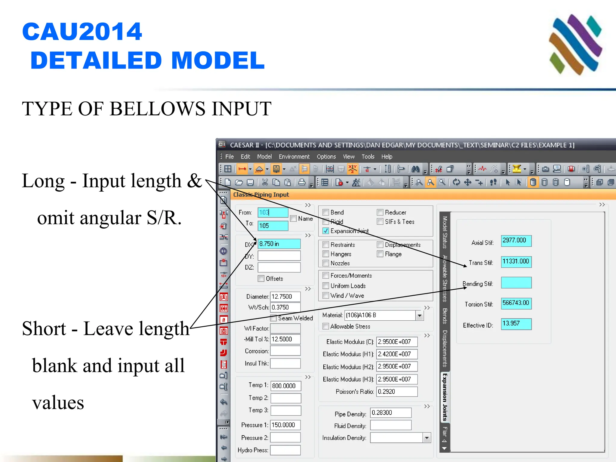
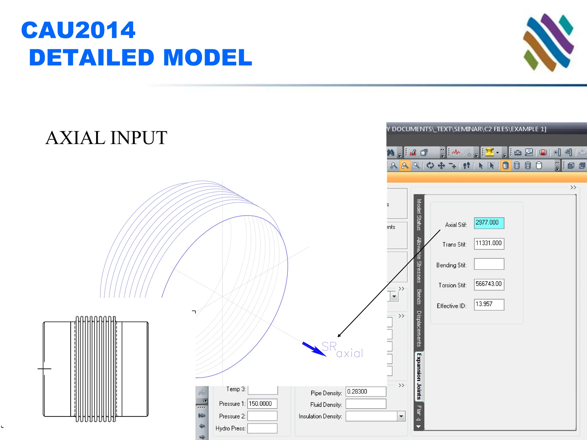
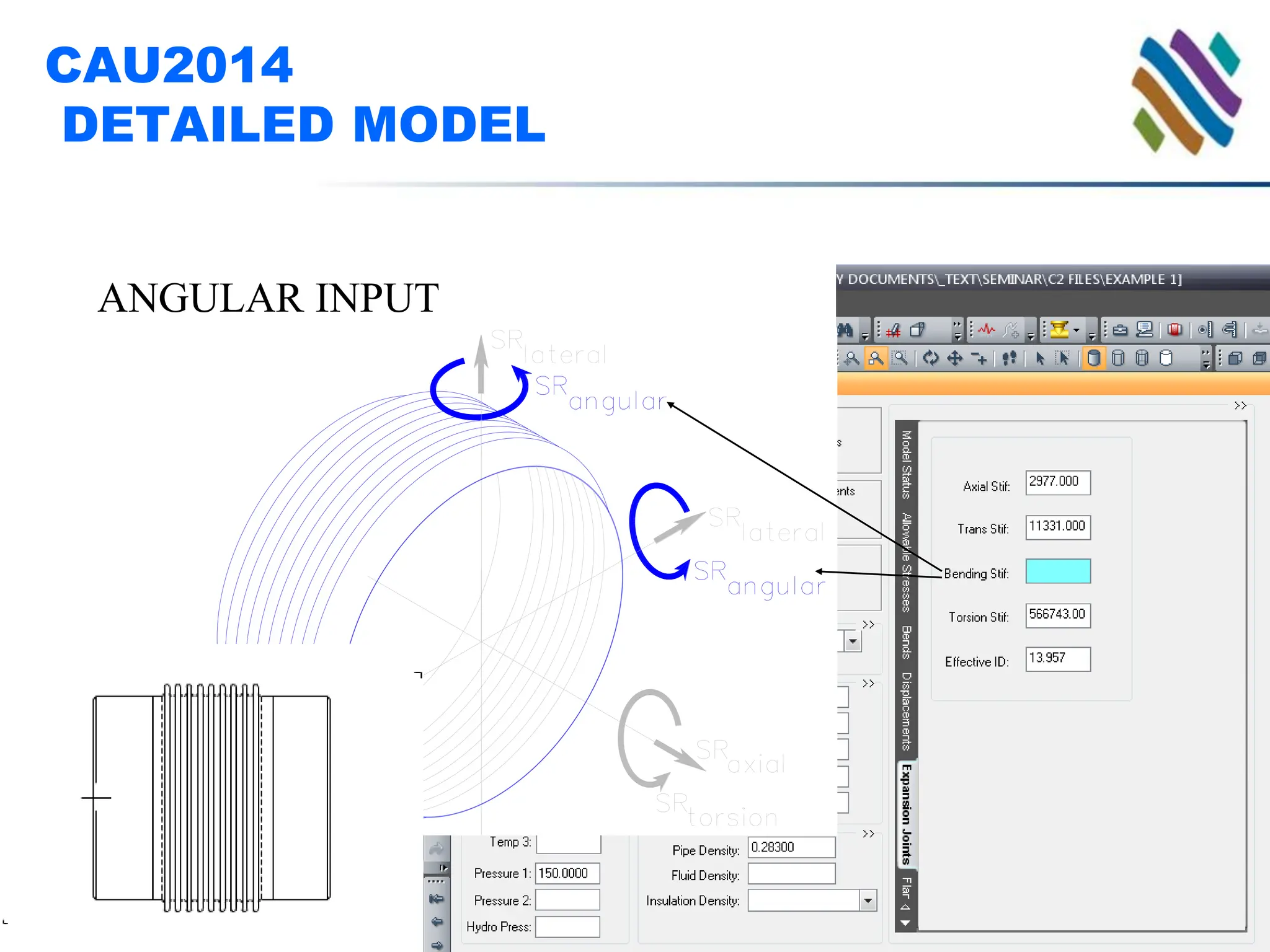
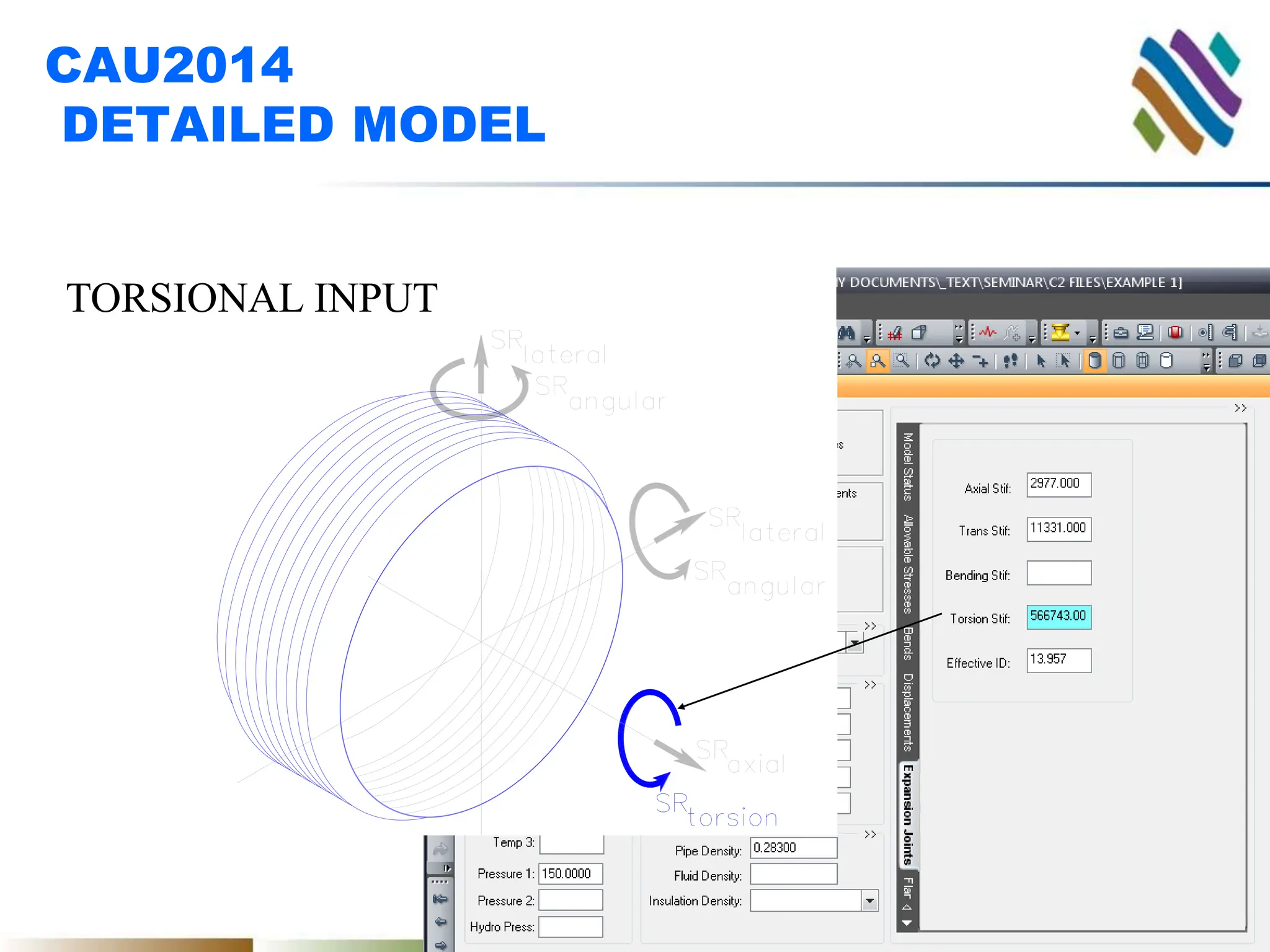
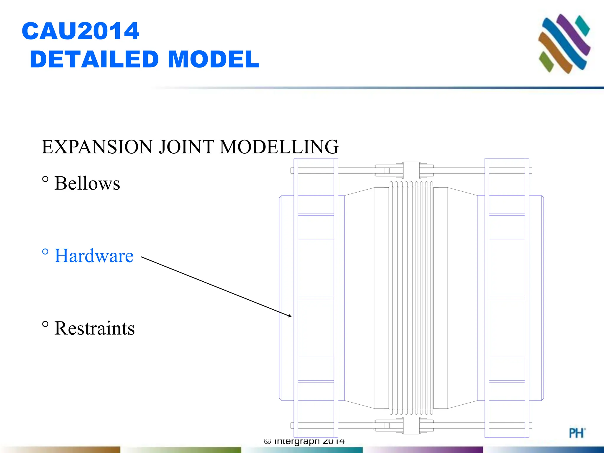
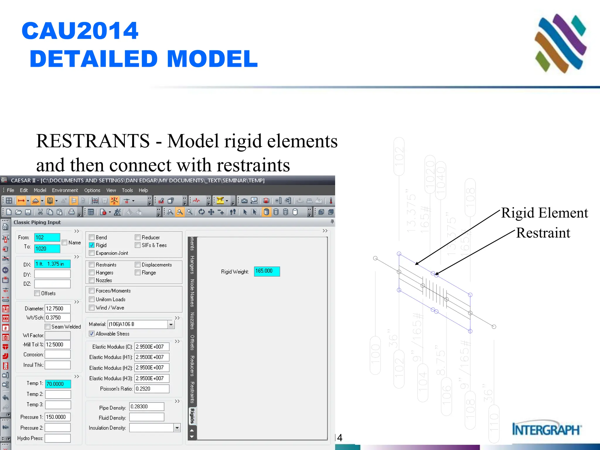
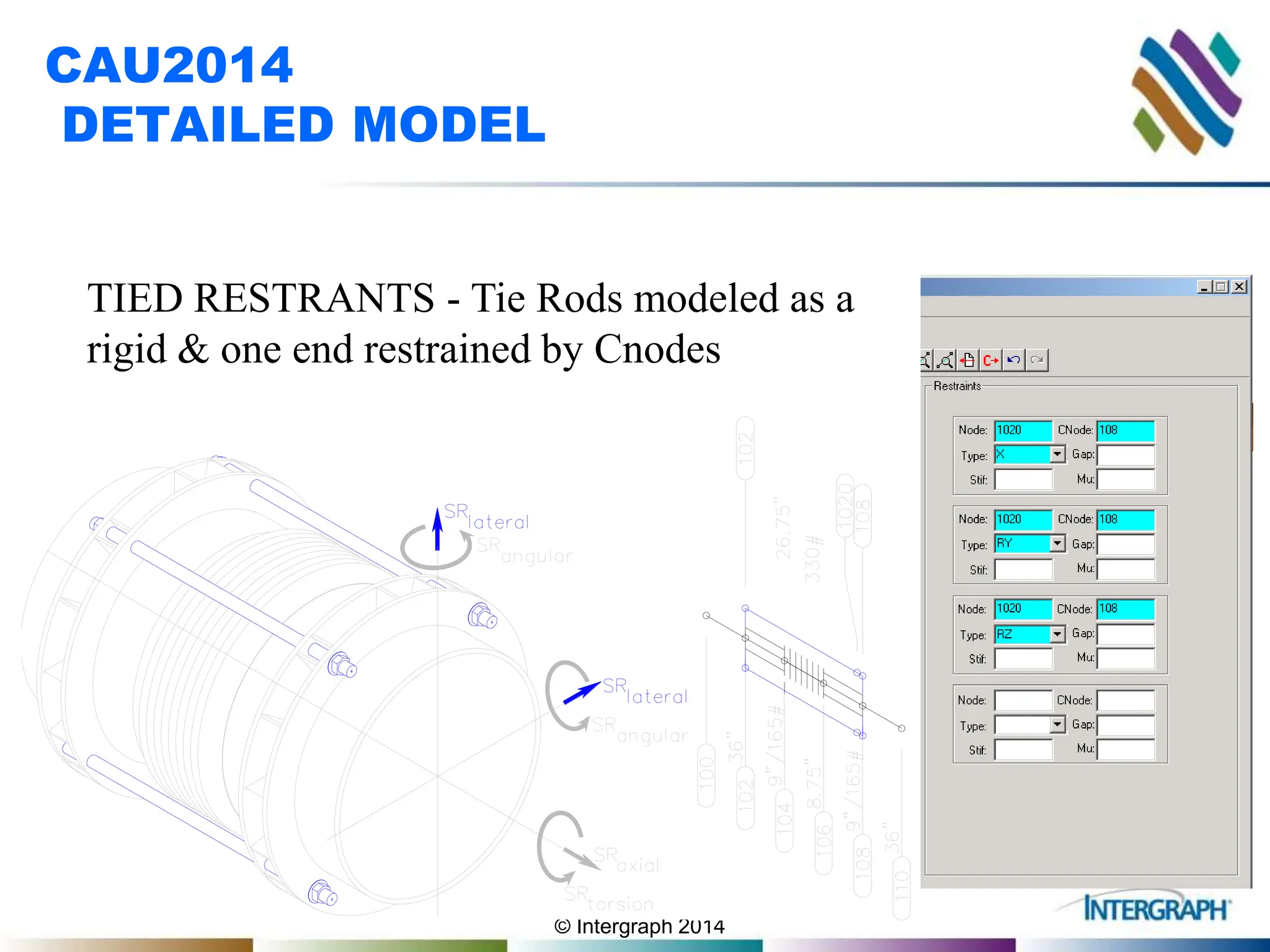
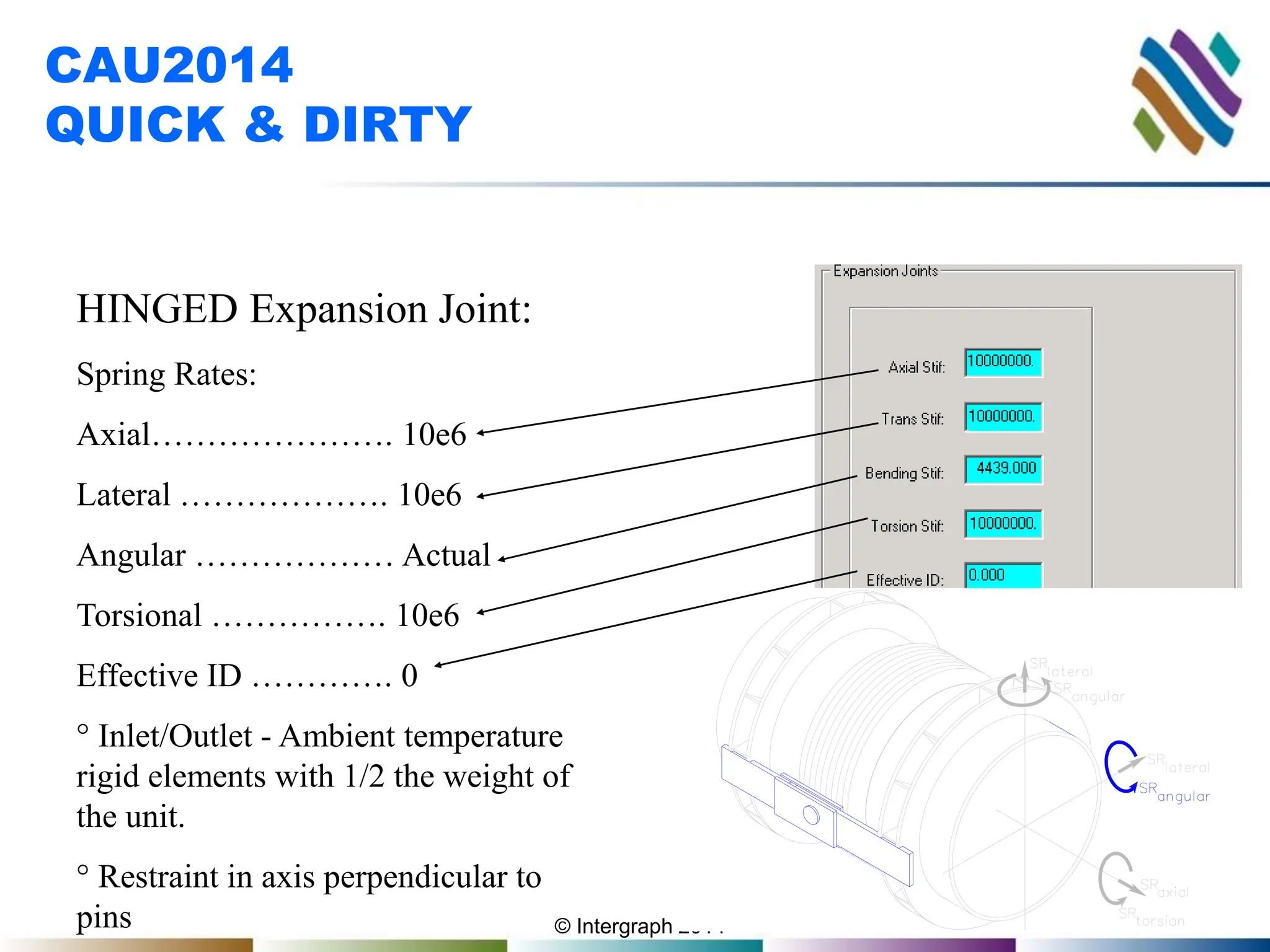
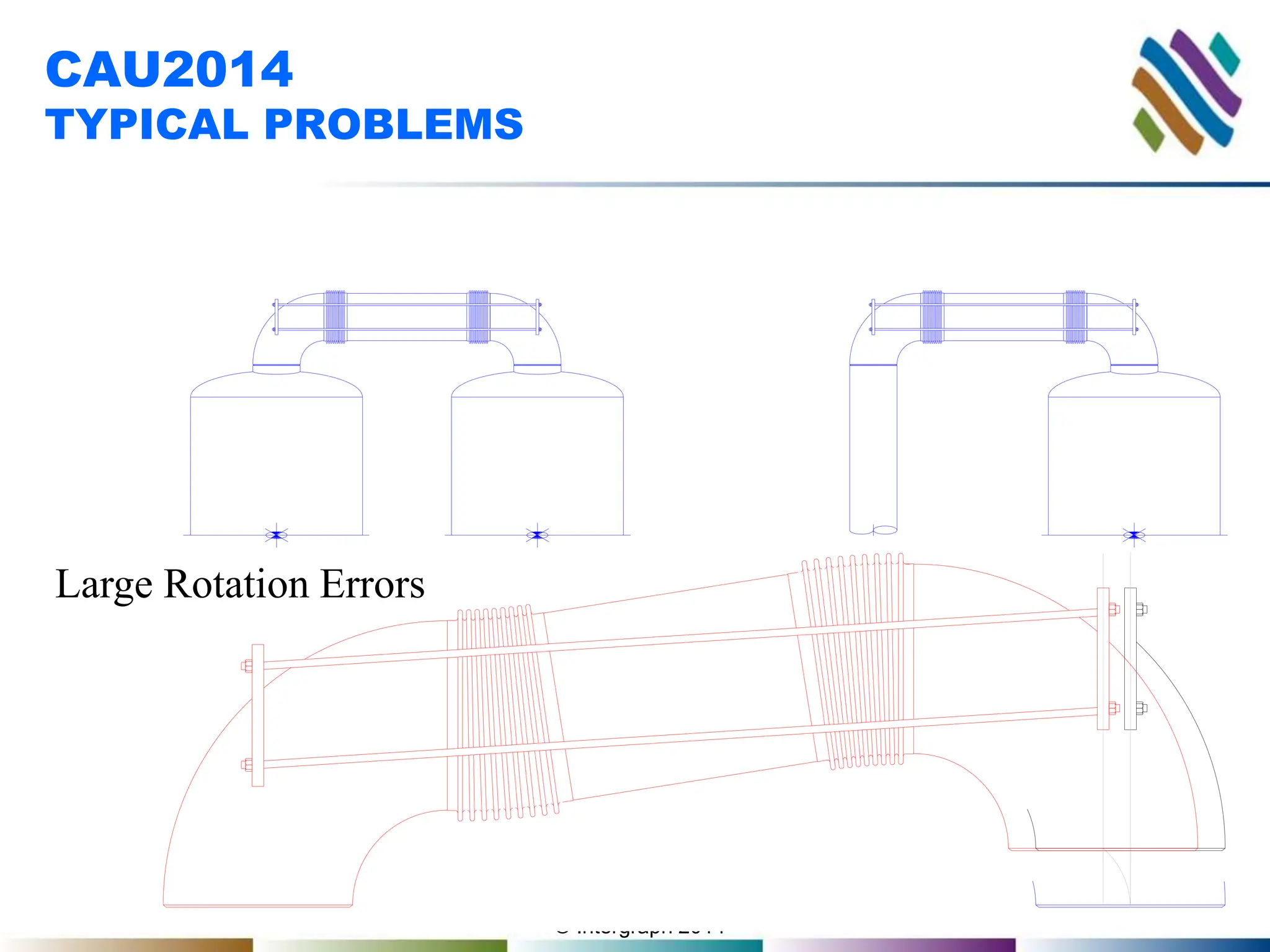
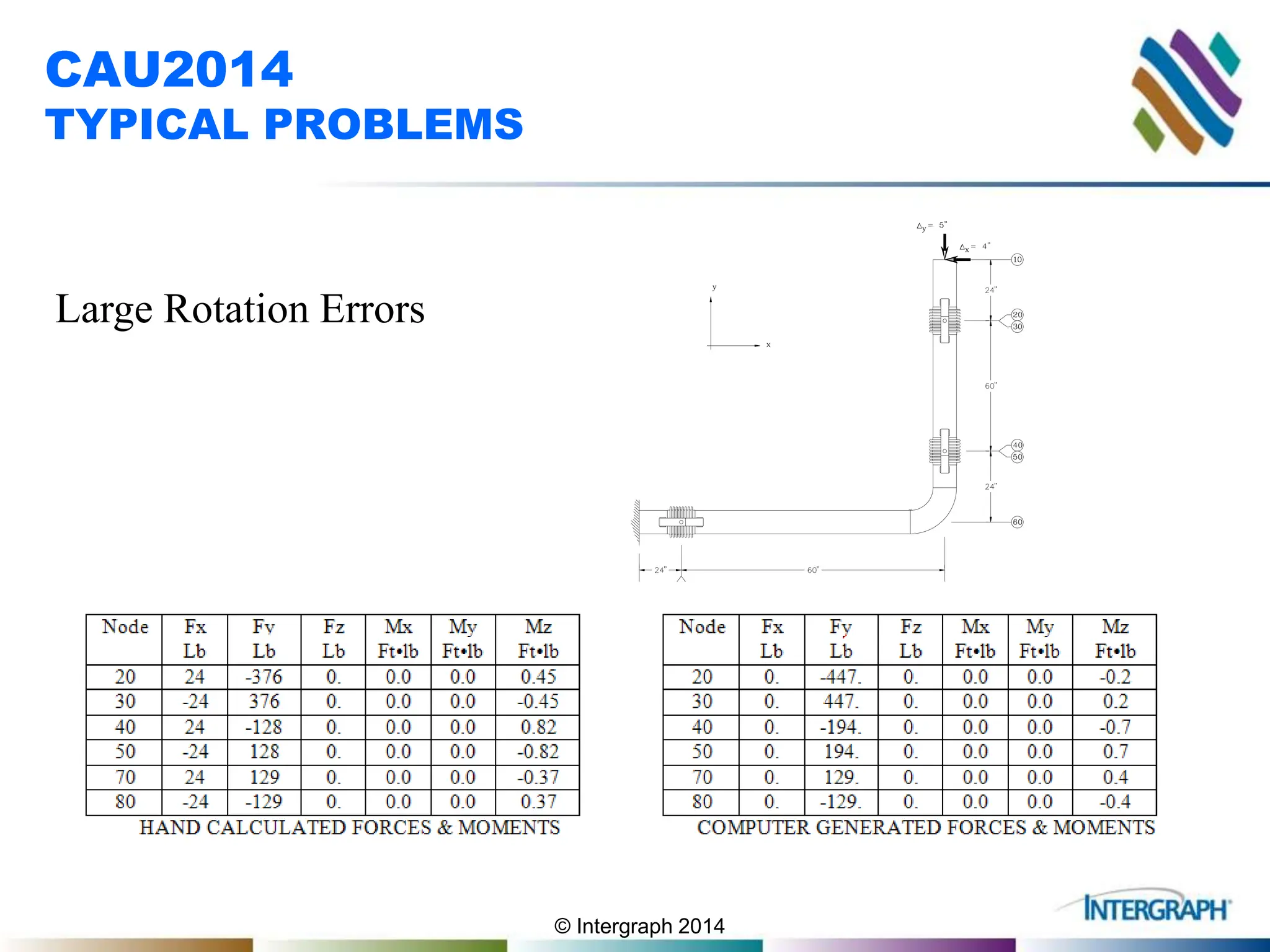
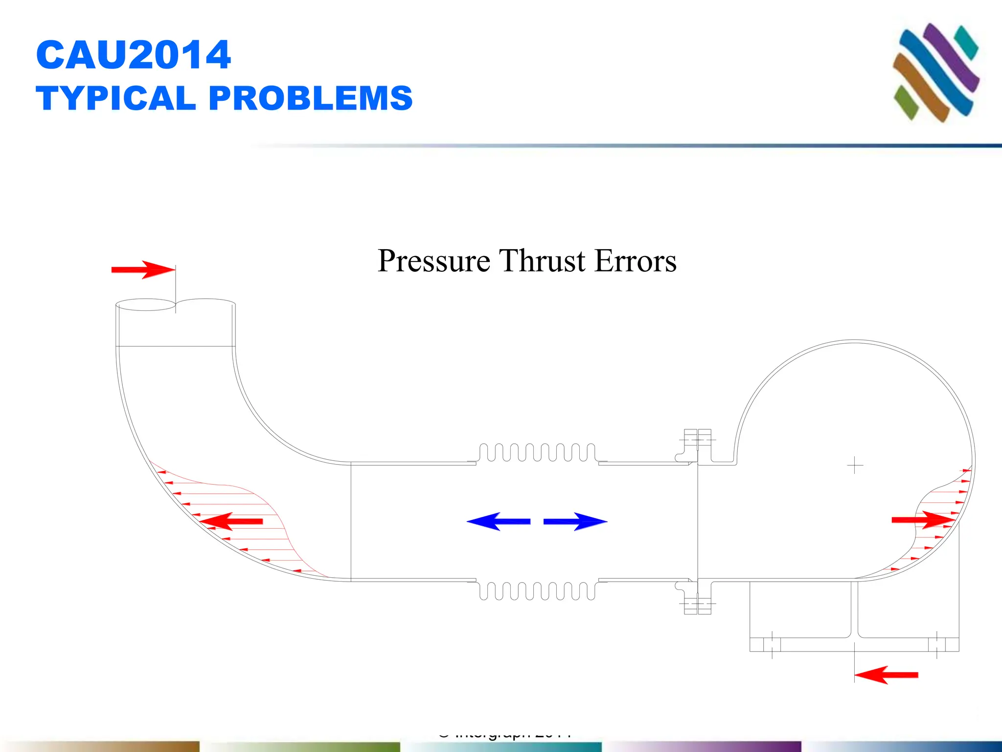
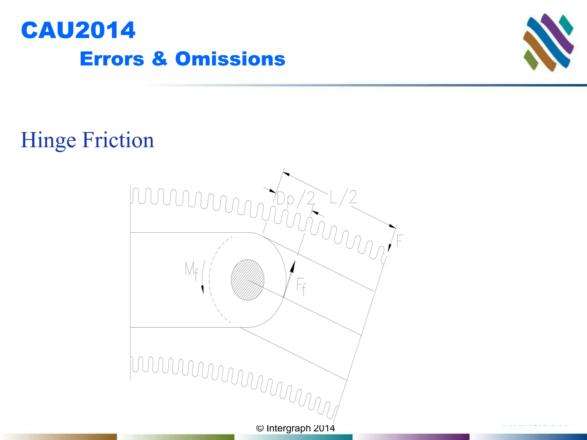
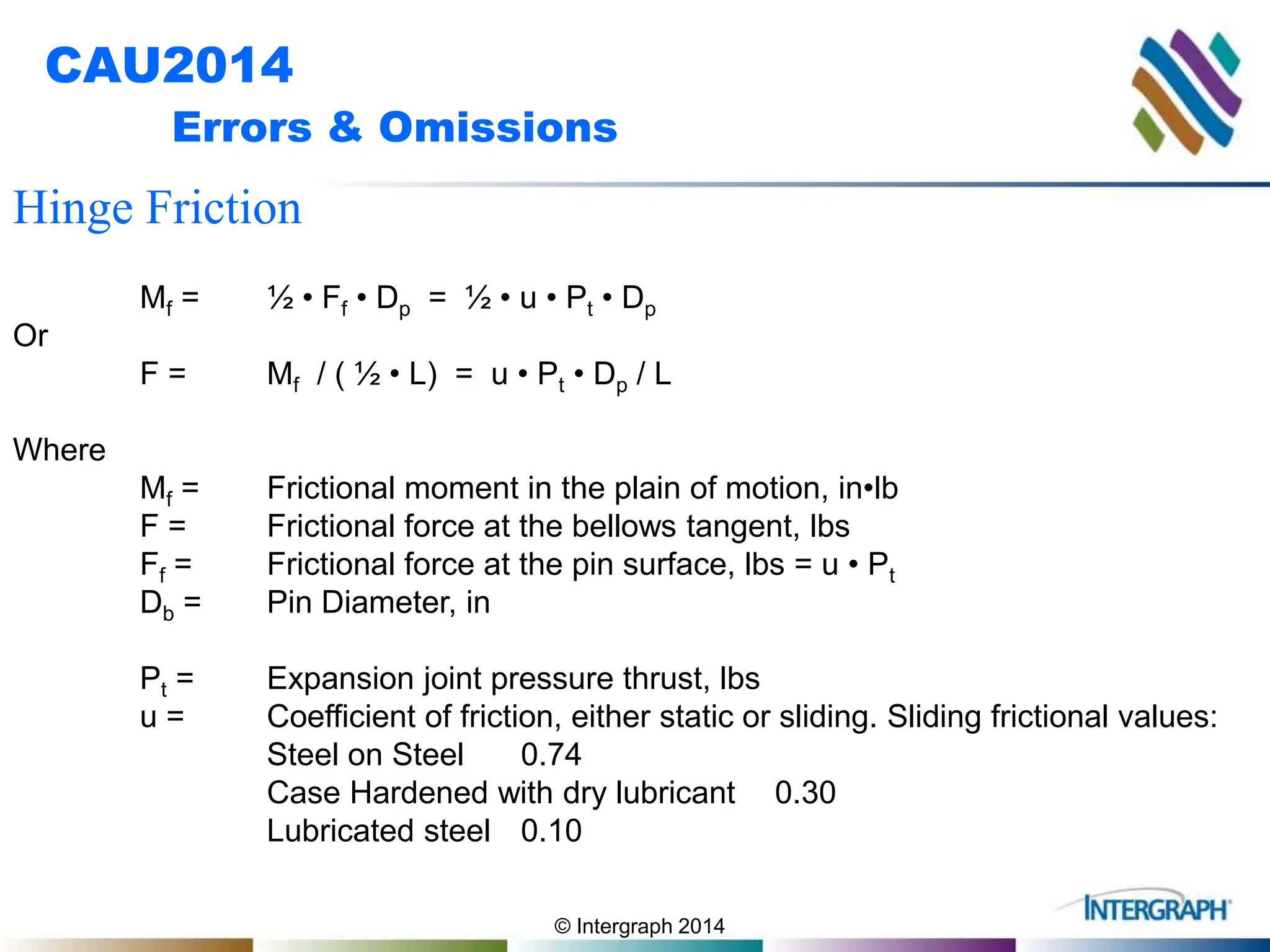
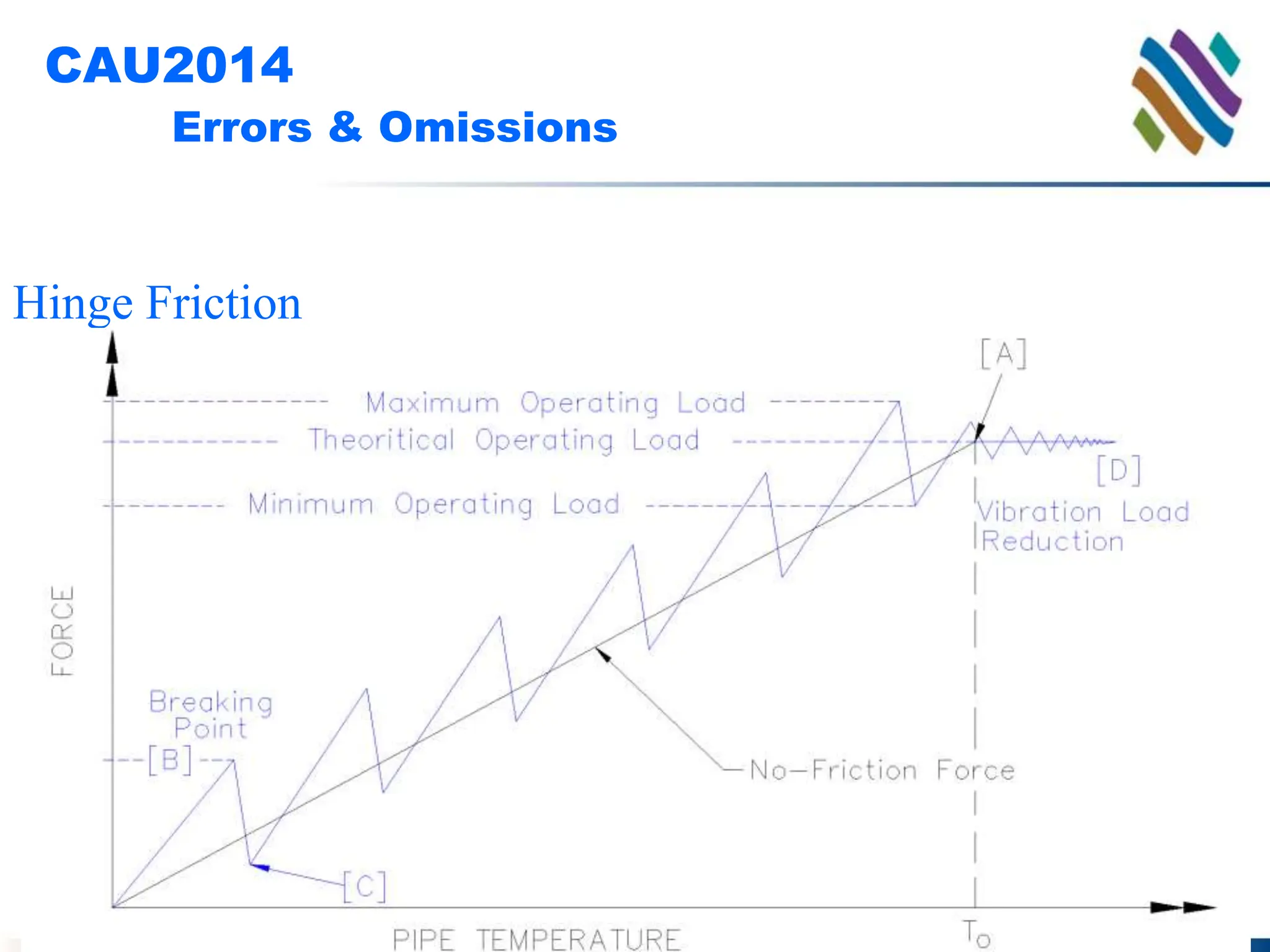
© Intergraph 2014
EXPANSION JOINTS WITH CAESAR II
Dan Edgar
Senior-Flexonics, Pathway Div
© Intergraph 2014
CAU2014
PIPING ANALYSIS
&
EXPANSION JOINTS
Detail Modeling
Automated Modeling
Quick & Dirty Modeling
Common Errors
© Intergraph 2014
CAU2014
DETAILED MODEL
DETAIL EXPANSION JOINT
MODELLING
° Bellows
° Hardware
° Restraints
© Intergraph 2014
CAU2014
DETAILED MODEL
EXPANSION JOINT MODELLING
° Bellows
° Hardware
° Restraints
© Intergraph 2014
CAU2014
DETAILED MODEL
TYPE OF BELLOWS INPUT
Long - Input length &
omit angular S/R.
Short - Leave length
blank and input all
values
© Intergraph 2014
CAU2014
DETAILED MODEL
AXIAL INPUT
© Intergraph 2014
CAU2014
DETAILED MODEL
LATERAL INPUT
© Intergraph 2014
CAU2014
DETAILED MODEL
ANGULAR INPUT
© Intergraph 2014
CAU2014
DETAILED MODEL
TORSIONAL INPUT
© Intergraph 2014
CAU2014
DETAILED MODEL
Effective ID
Effective ID = (Af ∙ 4 / p )1/2
Af = Effective Area
© Intergraph 2014
CAU2014
DETAILED MODEL
EXPANSION JOINT MODELLING
° Bellows
° Hardware
° Restraints
© Intergraph 2014
CAU2014
DETAILED MODEL
HARDWARE - Input 1/4 of joint
weight for each end of the expansion
joint
© Intergraph 2014
CAU2014
DETAILED MODEL
° Bellows
° Hardware
° Restraints
© Intergraph 2014
CAU2014
DETAILED MODEL
RESTRANTS - Model rigid elements
and then connect with restraints
Restraint
Rigid Element
© Intergraph 2014
CAU2014
DETAILED MODEL
TIED RESTRANTS - Tie Rods modeled as a
rigid & one end restrained by Cnodes
© Intergraph 2014
CAU2014
DETAILED MODEL
HINGE RESTRANTS - Arms joined at
centerline and then restrained by Cnodes
© Intergraph 2014
CAU2014
DETAILED MODEL
GIMBAL RESTRANTS - Arms joined at
centerline and then restrained by Cnodes
© Intergraph 2014
CAU2014
DETAILED MODEL
Pressure Balanced Elbow / Tee
© Intergraph 2014
CAU2014
DETAILED MODEL
Inline Pressure Balanced
© Intergraph 2014
CAU2014
AUTOMATED MODEL
AUTOMATED EXPANSION JOINT
MODELING
(EXPANSION JOINT DATABASE)
© Intergraph 2014
CAU2014
AUTOMATED MODEL
© Intergraph 2014
CAU2014
AUTOMATED MODEL
© Intergraph 2014
CAU2014
AUTOMATED MODEL
© Intergraph 2014
CAU2014
AUTOMATED MODEL
© Intergraph 2014
CAU2014
AUTOMATED MODEL
© Intergraph 2014
CAU2014
AUTOMATED MODEL
© Intergraph 2014
CAU2014
QUICK & DIRTY
QUICK & DIRTY EXPANSION JOINT
MODELING
(Tricking the computer)
© Intergraph 2014
CAU2014
QUICK & DIRTY
Manipulating line input to
model an expansion joints
° Use zero length bellows
° Include weight & length in
adjacent rigid elements
° Use an infinitely large (10e6)
spring rate to model a restraint
© Intergraph 2014
CAU2014
QUICK & DIRTY
TIED Expansion Joint:
Spring Rates:
Axial…………………. 10e6
Lateral ………………. Actual
Angular ……………… 10e6
Torsional ……………. Actual
Effective ID …………. 0
Inlet/Outlet - Ambient temperature
rigid elements with 1/2 the weight of
the unit
© Intergraph 2014
CAU2014
QUICK & DIRTY
HINGED Expansion Joint:
Spring Rates:
Axial…………………. 10e6
Lateral ………………. 10e6
Angular ……………… Actual
Torsional ……………. 10e6
Effective ID …………. 0
° Inlet/Outlet - Ambient temperature
rigid elements with 1/2 the weight of
the unit.
° Restraint in axis perpendicular to
pins
© Intergraph 2014
CAU2014
QUICK & DIRTY
GIMBAL Expansion Joint:
Spring Rates:
Axial…………………. 10e6
Lateral ………………. 10e6
Angular ……………… Actual
Torsional ……………. 10e6
Effective ID …………. 0
° Inlet/Outlet - Ambient temperature
rigid elements with 1/2 the weight of
the unit.
© Intergraph 2014
ERRORS & OMISSIONS
CAU2014
TYPICAL PROBLEMS
°Large Rotation Errors
°Relative Rigidity Errors
°Pressure Thrust Errors
© Intergraph 2014
CAU2014
TYPICAL PROBLEMS
Large Rotation Errors
© Intergraph 2014
CAU2014
TYPICAL PROBLEMS
Large Rotation Errors
© Intergraph 2014
CAU2014
TYPICAL PROBLEMS
Large Rotation Errors
© Intergraph 2014
CAU2014
TYPICAL PROBLEMS
Large Rotation Errors
© Intergraph 2014
CAU2014
TYPICAL PROBLEMS
Large Rotation Errors
© Intergraph 2014
CAU2014
TYPICAL PROBLEMS
Relative Rigidity Errors
© Intergraph 2014
CAU2014
TYPICAL PROBLEMS
Pressure Thrust Errors
© Intergraph 2014
CAU2014
TYPICAL PROBLEMS
Pressure Thrust Errors
© Intergraph 2014
CAU2014
TYPICAL PROBLEMS
Pressure Thrust Errors
© Intergraph 2014
CAU2014
Errors & Omissions
Hinge Friction
© Intergraph 2014
CAU2014
Errors & Omissions
Hinge Friction
Mf = ½ • Ff • Dp = ½ • u • Pt • Dp
Or
F = Mf / ( ½ • L) = u • Pt • Dp / L
Where
Mf = Frictional moment in the plain of motion, in•lb
F = Frictional force at the bellows tangent, lbs
Ff = Frictional force at the pin surface, lbs = u • Pt
Db = Pin Diameter, in
Pt = Expansion joint pressure thrust, lbs
u = Coefficient of friction, either static or sliding. Sliding frictional values:
Steel on Steel 0.74
Case Hardened with dry lubricant 0.30
Lubricated steel 0.10
© Intergraph 2014
CAU2014
Errors & Omissions
Hinge Friction
© Intergraph 2014
CAU2014
Errors & Omissions
Hinge Friction

2905_Edgar-EXPANSION-JOINTS-WITH-CAESAR-II.pptx