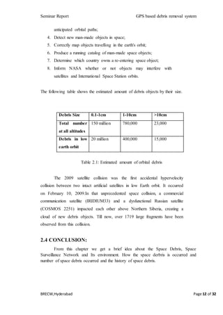
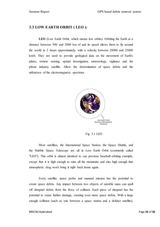
This document provides an overview of different types of orbits used for satellites, including low Earth orbit (LEO), medium Earth orbit (MEO), geostationary orbit (GEO), and highly elliptical orbit (HEO). It discusses the advantages and disadvantages of each orbit type, as well as their applications. Specific orbits like LEO are discussed in more detail, including factors like altitude and advantages like lower latency for communication satellites. The document also examines space debris and the increasing threat it poses to operational satellites from collisions. It notes there are over 20,000 pieces of debris larger than 10cm tracked in Earth's orbit.

![Seminar Report GPS based debris removal system
BRECW,Hyderabad Page 13 of 32
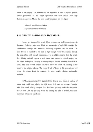
CHAPTER-III
TYPES OF ORBITS
3.1 INTRODUCTION:
Since the launch of the first satellite in 1957 humans have been placing
an increasing number of objects in orbit around the Earth. This trend has
accelerated in recent years thanks to the increase in number of states which have
the capability to launch satellites and the recognition of the many
socioeconomic and national security benefits that can be derived from space.
There are currently close to 1000 active satellites on orbit, operated by dozens
of state and international organizations. More importantly, each satellite that is
placed into orbit is accompanied by one or more pieces of non-functional
objects, known as space debris. More than 20,000 pieces of space debris larger
than 10 cm are regularly tracked in Earth orbit, and scientific research shows
that there are roughly 500,000 additional pieces between 1 and 10 cm in size
that are not regularly tracked. Although the average amount of space debris per
cubic kilometer is small, it is concentrated in the regions of Earth orbit that are
most heavily utilized…and thus poses a significant hazard to operational
spacecraft.
The artificial satellites are classified for the size (large >1000 kg, medium
size 500 –1000kg, small (mini satellites 100-500 kg, microsatellites 10-100 kg,
nano satellites 1-10 kg, pico satellites 0,1-1 kg and femto satellites <100 g)); for the
applications (exploration, communications, navigation and observation); for the
character (military, civil and dual); and for the orbital height (LEO, MEO,
HEO,GEO).
3.2 TYPES OF ORBITS:
Low Earth Orbit [LEO]
Medium Earth Orbit [MEO]
Highly Elliptical Orbits [HEO]
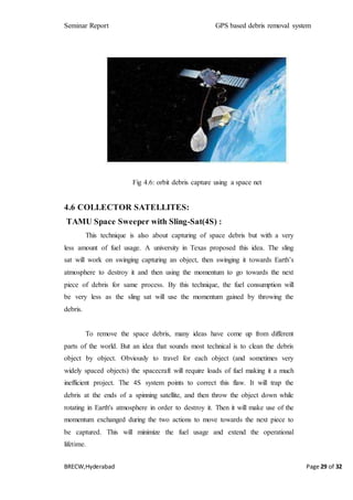
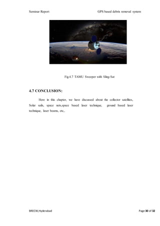
Geostationary Orbit [GEO]](https://image.slidesharecdn.com/476c7973-2989-45d6-b66d-7a5734d538bf-160303050044/85/21275-13-320.jpg)
![Seminar Report GPS based debris removal system
BRECW,Hyderabad Page 32 of 32
REFERENCES
[1] International Journal of Research (IJR) Vol-1, Issue-10 November
2014 ISSN 2348-6848 Space Debris Elimination Techniques.
[2] Robert Osiander and Paul Ostdiek, Handbook of Space
Engineering,
. Archeology.
[3] Marco M. Castronuovo, Active space debris removal-A preliminary
mission analysis and design, Acta Astronautica 69 (2011) 848-859.
[4] Carmen Pardini, Toshiya Hanada and Paula H Krisko, Benefits and
risks of using electrodynamic tethers to de-orbit spacecrafts, Acta
Astronautica 64 (2009) 571-588.
[5] Robert P Hoyt and Robert L Forward, The Terminator Tether:
Autonomous deorbit of LEO spacecraft for space debris mitigation,
AIAA-00—0329.
[6] Holger Burkhardt, Martin Sippel, et, Evaluation of propulsion
systems for satellite end-of-life deorbiting, Germany, AIAA-2002—
4208.
[7] Shin Ichiro Nishida, Satomi Kawamoto, etc. , Space debris removal
system using a small satellite, Acta Astronautica 65(2009) 95-102.
[8] Jonathan W Campbell, Using Lasers in Space: Laser Orbital debris
removal and asteroid deflection
[9] ―Position paper on orbital debris,‖ International Academy of
Astronautics, 8 March 1993.
[10] David S. F. Portree and Joseph P. Loftus, Jr., Orbital Debris and
Near-Earth Environmental Management: A Chronology, NASA
reference publication 1320, 1993.
[11] Patera, R. P., and Ailor, W. H., The realities of re-entry disposal,
AAS Paper 98-174, Feb. 1998.
[12] Vladimir A. Chobotov, Orbital Mechanics, 3rd ed., AIAA
education series, 2002.](https://image.slidesharecdn.com/476c7973-2989-45d6-b66d-7a5734d538bf-160303050044/85/21275-32-320.jpg)


![[Challenge:Future] Space Debris](https://cdn.slidesharecdn.com/ss_thumbnails/challengefuture-space-debris4808-111119075832-phpapp02-thumbnail.jpg?width=640&height=640&fit=bounds)