This workshop manual provides information for repairing Hino Trucks. It contains important safety precautions for working on vehicles and definitions of safety terms. The manual describes proper procedures for towing vehicles, rebuilding engines to comply with emissions regulations, and maintaining documentation of repair work. Technicians are instructed to follow the manual's organization by chapter and index, refer to troubleshooting sections, and order any special tools by part number.
2016 hino 358 series truck service repair manualjfdjjskekksemm
This workshop manual provides information for repairing Hino Trucks models 238, 258LP, 268, 338, 358 equipped with J08E-VB and J08E-VC engines. It contains general safety precautions and identifies vehicle components. Chapters cover various vehicle systems and components, with specifications for standard bolts and nuts. Proper vehicle lifting and support locations are shown. The manual instructs how to use diagnostic tools to simulate symptoms.
2013 hino 358 series truck service repair manualjfdjjskfkksmemm
This workshop manual provides information for repairing Hino Trucks models 238, 258LP, 268, 338, 358 equipped with J08E-VB and J08E-VC engines. It outlines general safety precautions when working on vehicles and describes how to use the manual. It includes sections on identification information, specifications, recommended lubricants, vehicle lifting points, and an information display. The document provides a table of contents to reference the appropriate chapter for different vehicle systems.
2012 hino 238 series truck service repair manualfusjejfjskekme
This workshop manual provides information for repairing Hino Trucks models 238, 258LP, 268, 338, 358 equipped with J08E-VB and J08E-VC engines. It contains general safety precautions for working on vehicles and identifies vehicle components that are covered in each chapter. Towing guidelines, clean air act requirements, and an overview of how to use the manual are also provided in 3 sentences or less.
2014 hino 338 series truck service repair manualfujsjefksekmfm
This document provides information and guidelines for repairing Hino Trucks, including the Hino 238, 258LP, 268, 338, 358 series equipped with J08E-VB and J08E-WU engines. It discusses general precautions for safety when working on vehicles and provides identification information. It also outlines how to use the workshop manual and specifies torque values for bolts and nuts. The document provides recommendations for lubricants and lifting locations when working under the vehicle. It includes an information display and instructions for symptom simulation. Chapter references are also included to direct the user to the appropriate section for their vehicle.
2017 hino 358 series truck service repair manualdufjsfjkskekem
This document provides information and guidelines for repairing Hino Trucks. It discusses general precautions when working on vehicles, identifying vehicle information, how to use the workshop manual, torque specifications, recommended lubricants, vehicle lift points, and an overview of the manual's chapter references. Safety is emphasized, including wearing protective equipment, parking the vehicle securely, avoiding hot or moving parts, and taking care with batteries. Towing procedures and clean air act requirements are also outlined.
2017 hino 268 series truck service repair manualufjjskekfmmse
This document provides information and guidelines for repairing Hino Trucks. It discusses general precautions to take when working on vehicles, identifies the truck models and engines covered, and outlines how to use the workshop manual. Torque specifications, recommended lubricants, vehicle lifting points, and an overview of the information display and symptom simulation are also included. The document is intended to help technicians service Hino vehicles safely and effectively.
2017 hino 258 lp series truck service repair manualufjjsjefkkekmme
This document provides information for repair procedures on Hino Trucks, including general precautions when working on vehicles and identifying vehicle specifications. It contains the following key points in 3 sentences:
The document outlines safety warnings and procedures for towing vehicles in need of repair. It also explains how to identify a vehicle using its identification number and specifications label. Technicians are directed to use this manual along with other relevant manuals when servicing components of Hino 238, 258LP, 268, 338, and 358 series trucks.
2017 hino 238 series truck service repair manualufjjsjefkkekmme
This document provides information for repair procedures on Hino Trucks, including general precautions when working on vehicles and identifying vehicle specifications. It contains the following key points in 3 sentences:
The document outlines safety warnings and procedures for towing vehicles in need of repair. It also explains how to identify a vehicle using its identification number and specifications label. Technicians are directed to use this manual along with other relevant manuals when servicing vehicles to ensure repairs are performed correctly.
2017 hino 238 series truck service repair manualfjjsjefkskemme
This document provides information and guidelines for repairing Hino Trucks. It discusses general precautions to take when working on vehicles, identifies the truck models and engines covered, and outlines how to use the workshop manual. Torque specifications, recommended lubricants, vehicle lifting points, and an overview of the information display and symptom simulation are also included. The document is intended to help technicians service Hino vehicles safely and effectively.
2017 hino 338 series truck service repair manualufjsjekskem
This document provides information for repair procedures on Hino Trucks, including general precautions when working on vehicles and identifying vehicle information. It discusses vehicle identification numbers, production codes, components, and specifications. It also outlines how to use the workshop manual, precautions, torque specifications, vehicle lifting points, and other technical details to safely and properly service vehicles.
2014 hino 268 series truck service repair manualfujsejfkskefmem
This workshop manual provides information for repairing Hino Trucks models 238, 258LP, 268, 338, 358 equipped with J08E-VB and J08E-WU engines. It contains general safety precautions and identifies vehicle components. Chapters cover various vehicle systems and components, with references to identify applicable chapters for specific models. Instructions are provided for properly using and maintaining the vehicle, along with definitions of terms.
2014 hino 258 lp series truck service repair manualfusjejfkskeme
This document provides information and guidelines for repairing Hino Trucks, including the Hino 238, 258LP, 268, 338, 358 series equipped with J08E-VB and J08E-WU engines. It discusses general precautions for safety when working on vehicles, identifies the vehicle models covered, and how to use the workshop manual. It also includes specifications for torque values, recommended lubricants, vehicle lift points, and provides an overview of the manual's contents and chapter references.
This document provides information and guidelines for repairing Hino Trucks, including the Hino 238, 258LP, 268, 338, 358 series equipped with J08E-VB and J08E-WU engines. It discusses general precautions for safety when working on vehicles and identifies the vehicle. The document also outlines how to use the workshop manual, specifies torques for bolts and nuts, recommends lubricants, and identifies vehicle lift points. Symptom simulation and other troubleshooting information is also included.
2013 hino 268 series truck service repair manualfjjskksekmemm
This workshop manual chapter provides information for servicing the clutch main unit on Hino trucks. It includes data and specifications, descriptions of components, troubleshooting guidance, locations of special tools, and overhaul procedures for the Eaton 1401 clutch assembly. Technicians can refer to this chapter to diagnose clutch issues, identify replacement parts, and correctly repair and reassemble the clutch main unit. The manual aims to ensure repairs are performed safely and effectively.
2016 hino 338 series truck service repair manualjfjskeksemm
This workshop manual provides information for repairing Hino Trucks models 238, 258LP, 268, 338, 358 equipped with J08E-VB and J08E-VC engines. It contains general safety precautions and identifies vehicle components. Chapters cover various vehicle systems and components, with specifications for repairs. Proper maintenance following the manual's instructions helps ensure vehicle and technician safety.
2016 hino 268 series truck service repair manualjfdjjskfkksmemm
This workshop manual provides information for repairing Hino Trucks models 238, 258LP, 268, 338, 358 equipped with J08E-VB and J08E-VC engines. It contains general safety precautions and identifies vehicle components. Chapters cover various vehicle systems and components, with specifications for servicing different vehicle models. Precautions are given for lifting vehicles, running engines, and vehicle towing. Regulations regarding engine rebuilding practices and maintenance instructions are also provided.
2016 hino 238 series truck service repair manualfjjskksekmemm
This workshop manual provides information for repairing Hino Trucks models 238, 258LP, 268, 338, 358 equipped with J08E-VB and J08E-VC engines. It contains general safety precautions and identifies vehicle components that are covered in each chapter. Lubrication recommendations and specifications for standard bolts and nuts are also included, as well as information on vehicle lifting points, the onboard display, and symptom simulation.
2016 hino 238 series truck service repair manualfjsjjefskekmem
This workshop manual provides information for repairing Hino Trucks models 238, 258LP, 268, 338, 358 equipped with J08E-VB and J08E-VC engines. It contains general safety precautions and identifies vehicle components that are covered in each chapter. Lubrication recommendations and specifications for standard bolts and nuts are also included.
2013 hino 268 series truck service repair manualfjsjjefskekmem
This workshop manual chapter provides information for servicing the clutch main unit on Hino trucks. It includes data and specifications, descriptions of components, troubleshooting steps, locations of special tools, and overhaul procedures for the clutch assembly. Technicians are instructed to refer to the troubleshooting section first to guide diagnosis when beginning work. Special tools are also identified to ensure correct parts are ordered. Detailed repair procedures are provided where needed, with illustrations to clarify simple installation and removal steps. Records of work performed are required to be kept.
2012 hino 338 series truck service repair manualfjjjskekksmem
This workshop manual provides information for repairing Hino Trucks models 238, 258LP, 268, 338, 358 equipped with J08E-VB and J08E-VC engines. It contains general safety precautions for working on vehicles and identifies vehicle components that are covered in each chapter. Towing guidelines, clean air act requirements, and an overview of how to use the manual are also provided in 3 sentences or less.
Yanmar 4 jh4ae marine diesel engine service repair manualfjjksekfksmem
This document is the service manual for Yanmar JH4 series marine engines. It contains safety information, maintenance procedures, troubleshooting steps, and specifications for the JH4, 3JH4E, 4JH4AE, 4JH4-TE, and 4JH4-HTE engines. The manual provides instructions for proper repair and maintenance to ensure quality service. Readers are advised to follow the procedures carefully and use recommended special tools for repairs.
Yamaha outboard 40 vehto, p40th service repair manual l 430386 fjjksekfksmem
This document provides a service manual for 40V, 50H outboard motors. It includes an index listing chapters covering general information, specifications, periodic inspection and adjustment, fuel system, power unit, lower unit, bracket unit, electrical system, and trouble analysis. The general information chapter discusses identification, safety practices, special tools, measuring tools, and tools for removal and installation. It provides guidance on safe work practices and proper use of special tools.
Yamaha g9 ah golf cart service repair manualfjjksekfksmem
This document is a Yamaha service manual that provides information on servicing Yamaha G2-A and G2-E vehicles. It contains chapters covering general information, specifications, periodic inspection and adjustment procedures, engine overhaul, carburetion, power train, chassis, electrical systems, troubleshooting, and special tools required for service. The document provides detailed instructions and specifications to guide technicians in properly servicing and repairing these vehicles.
Yale c875 glp20 vx lift truck service repair manualfjjksekfksmem
The document provides service manual contents and procedures for removing an operator cab from various forklift truck models. It contains the following key points:
- The operator cab is a separate unit that can be removed as a complete module from the forklift frame.
- Steps include tilting the steering column, sliding the seat forward, disconnecting battery and air filter hoses, draining coolant and removing radiator cap, disconnecting heater hoses and refrigerant lines (if equipped), and removing side door assemblies.
- Special precautions are outlined for working with pressurized cooling systems and refrigerants, as well as different cab configurations among the various forklift models.
Yale b888 erp15 vc lift truck service repair manualfjjksekfksmem
This document provides service information for replacing the front window panel on several lift truck models. It describes:
1) Removing nuts, bolts and washers to detach the front window panel from the overhead guard.
2) Removing additional hardware and brackets to fully remove the front window panel.
3) Cleaning and inspecting the front window panel and other components before reinstallation.
4) Noting placement of components during removal to aid in reinstallation.
Yale b875 gp070 vx lift truck service repair manualfjjksekfksmem
This document is a service manual that contains sections on repairing various components of a forklift. It provides:
1) A table of contents listing the document sections by part number, section number, revision date.
2) A description of the forklift frame that includes the hydraulic tank, fuel tank, counterweight, overhead guard, hood, and covers. Safety procedures are provided for when putting the forklift on blocks for maintenance.
3) Instructions for removing the hood, seat, and side covers to access components like the engine and transmission.
Yale b875 gdp35 vx lift truck service repair manualfjjksekfksmem
This document provides a service manual for GLP/GDP20VX, GLP/GDP25VX, GLP/GDP30VX, GLP/GDP35VX lift trucks. It contains sections on frame components, engine repair, transmissions, axles, hydraulics and more. The frame includes the counterweight, fuel tank, hydraulic tank and mounts the overhead guard, hood and other parts. Procedures are provided for removing the counterweight, hood, side covers and accessing components. Safety precautions are described for when the lift truck is supported on blocks for maintenance.
Yale b814 erp16 20 aaf lift truck service repair manualfjjksekfksmem
This document contains:
1. A service manual table of contents listing maintenance sections for various lift truck parts.
2. A description of the main frame and its components including the counterweight, overhead guard, hood, and access panels.
3. Descriptions of other frame components including the cowl weldment, side step and fender weldments.
4. Information on battery compartment specifications and overhead guard installation.
Yale a839 erc100 hg lift truck service repair manualfjjksekfksmem
This document provides a service manual for the ERC070-120HG lift truck models. It contains sections on various parts of the lift truck including the frame, motors, axles, steering, brakes, hydraulics, controls, batteries, masts, cylinders and fasteners. The document describes the frame design and components, provides specifications for battery size and weight, and describes how to adjust spacers in the battery compartment. It also provides instructions for removing and installing the overhead guard.
Yale (d875) gp070 vx lift truck service repair manualfjjksekfksmem
The document provides instructions for removing an operator cab from a forklift. Key steps include:
1. Tilting the steering column up, sliding the seat forward, opening rear doors/windows, and disconnecting the battery.
2. Disconnecting air filter hoses, removing radiator covers, and draining coolant lines.
3. For models with air conditioning, extracting refrigerant and disconnecting AC lines.
4. Disconnecting wiring harnesses, heater lines, gas springs and removing door assemblies. The cab can then be lifted off as a complete unit.
More Related Content
Similar to 2014 hino 238 series truck service repair manual
2017 hino 238 series truck service repair manualfjjsjefkskemme
This document provides information and guidelines for repairing Hino Trucks. It discusses general precautions to take when working on vehicles, identifies the truck models and engines covered, and outlines how to use the workshop manual. Torque specifications, recommended lubricants, vehicle lifting points, and an overview of the information display and symptom simulation are also included. The document is intended to help technicians service Hino vehicles safely and effectively.
2017 hino 338 series truck service repair manualufjsjekskem
This document provides information for repair procedures on Hino Trucks, including general precautions when working on vehicles and identifying vehicle information. It discusses vehicle identification numbers, production codes, components, and specifications. It also outlines how to use the workshop manual, precautions, torque specifications, vehicle lifting points, and other technical details to safely and properly service vehicles.
2014 hino 268 series truck service repair manualfujsejfkskefmem
This workshop manual provides information for repairing Hino Trucks models 238, 258LP, 268, 338, 358 equipped with J08E-VB and J08E-WU engines. It contains general safety precautions and identifies vehicle components. Chapters cover various vehicle systems and components, with references to identify applicable chapters for specific models. Instructions are provided for properly using and maintaining the vehicle, along with definitions of terms.
2014 hino 258 lp series truck service repair manualfusjejfkskeme
This document provides information and guidelines for repairing Hino Trucks, including the Hino 238, 258LP, 268, 338, 358 series equipped with J08E-VB and J08E-WU engines. It discusses general precautions for safety when working on vehicles, identifies the vehicle models covered, and how to use the workshop manual. It also includes specifications for torque values, recommended lubricants, vehicle lift points, and provides an overview of the manual's contents and chapter references.
This document provides information and guidelines for repairing Hino Trucks, including the Hino 238, 258LP, 268, 338, 358 series equipped with J08E-VB and J08E-WU engines. It discusses general precautions for safety when working on vehicles and identifies the vehicle. The document also outlines how to use the workshop manual, specifies torques for bolts and nuts, recommends lubricants, and identifies vehicle lift points. Symptom simulation and other troubleshooting information is also included.
2013 hino 268 series truck service repair manualfjjskksekmemm
This workshop manual chapter provides information for servicing the clutch main unit on Hino trucks. It includes data and specifications, descriptions of components, troubleshooting guidance, locations of special tools, and overhaul procedures for the Eaton 1401 clutch assembly. Technicians can refer to this chapter to diagnose clutch issues, identify replacement parts, and correctly repair and reassemble the clutch main unit. The manual aims to ensure repairs are performed safely and effectively.
2016 hino 338 series truck service repair manualjfjskeksemm
This workshop manual provides information for repairing Hino Trucks models 238, 258LP, 268, 338, 358 equipped with J08E-VB and J08E-VC engines. It contains general safety precautions and identifies vehicle components. Chapters cover various vehicle systems and components, with specifications for repairs. Proper maintenance following the manual's instructions helps ensure vehicle and technician safety.
2016 hino 268 series truck service repair manualjfdjjskfkksmemm
This workshop manual provides information for repairing Hino Trucks models 238, 258LP, 268, 338, 358 equipped with J08E-VB and J08E-VC engines. It contains general safety precautions and identifies vehicle components. Chapters cover various vehicle systems and components, with specifications for servicing different vehicle models. Precautions are given for lifting vehicles, running engines, and vehicle towing. Regulations regarding engine rebuilding practices and maintenance instructions are also provided.
2016 hino 238 series truck service repair manualfjjskksekmemm
This workshop manual provides information for repairing Hino Trucks models 238, 258LP, 268, 338, 358 equipped with J08E-VB and J08E-VC engines. It contains general safety precautions and identifies vehicle components that are covered in each chapter. Lubrication recommendations and specifications for standard bolts and nuts are also included, as well as information on vehicle lifting points, the onboard display, and symptom simulation.
2016 hino 238 series truck service repair manualfjsjjefskekmem
This workshop manual provides information for repairing Hino Trucks models 238, 258LP, 268, 338, 358 equipped with J08E-VB and J08E-VC engines. It contains general safety precautions and identifies vehicle components that are covered in each chapter. Lubrication recommendations and specifications for standard bolts and nuts are also included.
2013 hino 268 series truck service repair manualfjsjjefskekmem
This workshop manual chapter provides information for servicing the clutch main unit on Hino trucks. It includes data and specifications, descriptions of components, troubleshooting steps, locations of special tools, and overhaul procedures for the clutch assembly. Technicians are instructed to refer to the troubleshooting section first to guide diagnosis when beginning work. Special tools are also identified to ensure correct parts are ordered. Detailed repair procedures are provided where needed, with illustrations to clarify simple installation and removal steps. Records of work performed are required to be kept.
2012 hino 338 series truck service repair manualfjjjskekksmem
This workshop manual provides information for repairing Hino Trucks models 238, 258LP, 268, 338, 358 equipped with J08E-VB and J08E-VC engines. It contains general safety precautions for working on vehicles and identifies vehicle components that are covered in each chapter. Towing guidelines, clean air act requirements, and an overview of how to use the manual are also provided in 3 sentences or less.
Similar to 2014 hino 238 series truck service repair manual (12)
Yanmar 4 jh4ae marine diesel engine service repair manualfjjksekfksmem
This document is the service manual for Yanmar JH4 series marine engines. It contains safety information, maintenance procedures, troubleshooting steps, and specifications for the JH4, 3JH4E, 4JH4AE, 4JH4-TE, and 4JH4-HTE engines. The manual provides instructions for proper repair and maintenance to ensure quality service. Readers are advised to follow the procedures carefully and use recommended special tools for repairs.
Yamaha outboard 40 vehto, p40th service repair manual l 430386 fjjksekfksmem
This document provides a service manual for 40V, 50H outboard motors. It includes an index listing chapters covering general information, specifications, periodic inspection and adjustment, fuel system, power unit, lower unit, bracket unit, electrical system, and trouble analysis. The general information chapter discusses identification, safety practices, special tools, measuring tools, and tools for removal and installation. It provides guidance on safe work practices and proper use of special tools.
Yamaha g9 ah golf cart service repair manualfjjksekfksmem
This document is a Yamaha service manual that provides information on servicing Yamaha G2-A and G2-E vehicles. It contains chapters covering general information, specifications, periodic inspection and adjustment procedures, engine overhaul, carburetion, power train, chassis, electrical systems, troubleshooting, and special tools required for service. The document provides detailed instructions and specifications to guide technicians in properly servicing and repairing these vehicles.
Yale c875 glp20 vx lift truck service repair manualfjjksekfksmem
The document provides service manual contents and procedures for removing an operator cab from various forklift truck models. It contains the following key points:
- The operator cab is a separate unit that can be removed as a complete module from the forklift frame.
- Steps include tilting the steering column, sliding the seat forward, disconnecting battery and air filter hoses, draining coolant and removing radiator cap, disconnecting heater hoses and refrigerant lines (if equipped), and removing side door assemblies.
- Special precautions are outlined for working with pressurized cooling systems and refrigerants, as well as different cab configurations among the various forklift models.
Yale b888 erp15 vc lift truck service repair manualfjjksekfksmem
This document provides service information for replacing the front window panel on several lift truck models. It describes:
1) Removing nuts, bolts and washers to detach the front window panel from the overhead guard.
2) Removing additional hardware and brackets to fully remove the front window panel.
3) Cleaning and inspecting the front window panel and other components before reinstallation.
4) Noting placement of components during removal to aid in reinstallation.
Yale b875 gp070 vx lift truck service repair manualfjjksekfksmem
This document is a service manual that contains sections on repairing various components of a forklift. It provides:
1) A table of contents listing the document sections by part number, section number, revision date.
2) A description of the forklift frame that includes the hydraulic tank, fuel tank, counterweight, overhead guard, hood, and covers. Safety procedures are provided for when putting the forklift on blocks for maintenance.
3) Instructions for removing the hood, seat, and side covers to access components like the engine and transmission.
Yale b875 gdp35 vx lift truck service repair manualfjjksekfksmem
This document provides a service manual for GLP/GDP20VX, GLP/GDP25VX, GLP/GDP30VX, GLP/GDP35VX lift trucks. It contains sections on frame components, engine repair, transmissions, axles, hydraulics and more. The frame includes the counterweight, fuel tank, hydraulic tank and mounts the overhead guard, hood and other parts. Procedures are provided for removing the counterweight, hood, side covers and accessing components. Safety precautions are described for when the lift truck is supported on blocks for maintenance.
Yale b814 erp16 20 aaf lift truck service repair manualfjjksekfksmem
This document contains:
1. A service manual table of contents listing maintenance sections for various lift truck parts.
2. A description of the main frame and its components including the counterweight, overhead guard, hood, and access panels.
3. Descriptions of other frame components including the cowl weldment, side step and fender weldments.
4. Information on battery compartment specifications and overhead guard installation.
Yale a839 erc100 hg lift truck service repair manualfjjksekfksmem
This document provides a service manual for the ERC070-120HG lift truck models. It contains sections on various parts of the lift truck including the frame, motors, axles, steering, brakes, hydraulics, controls, batteries, masts, cylinders and fasteners. The document describes the frame design and components, provides specifications for battery size and weight, and describes how to adjust spacers in the battery compartment. It also provides instructions for removing and installing the overhead guard.
Yale (d875) gp070 vx lift truck service repair manualfjjksekfksmem
The document provides instructions for removing an operator cab from a forklift. Key steps include:
1. Tilting the steering column up, sliding the seat forward, opening rear doors/windows, and disconnecting the battery.
2. Disconnecting air filter hoses, removing radiator covers, and draining coolant lines.
3. For models with air conditioning, extracting refrigerant and disconnecting AC lines.
4. Disconnecting wiring harnesses, heater lines, gas springs and removing door assemblies. The cab can then be lifted off as a complete unit.
Yale (c875) gtp70 vx lift truck service repair manualfjjksekfksmem
The document provides instructions for removing an operator cab from various lift truck models. Key steps include:
1. Tilting the steering column, sliding the seat forward, and opening doors/windows to access components.
2. Disconnecting the air filter hose, radiator hoses, and extracting refrigerant from air conditioning systems.
3. Removing fasteners and disconnecting electrical connections to fully separate the cab unit for removal. Precautions are listed for high temperature and high pressure components.
Perkins 400 series 402 d 403d 404d industrial engine (model gm) service repai...fjjksekfksmem
This document provides instructions for disassembling and assembling various components of Perkins 402D-403D-404D industrial diesel engines, including removal and installation procedures for items like the fuel filter base, fuel transfer pump, fuel lines, fuel injection pump, turbocharger, valves, pistons, bearings, and other parts. Safety warnings are provided to prevent injury when performing maintenance on these engines.
New holland t8030 tractor service repair manualfjjksekfksmem
This document provides a master table of contents for a tractor repair manual. It lists sections and chapters covering topics like standard torque specifications, safety information, engine removal and installation, fuel tank removal, hood removal, cooling system removal, transmission system operation, splitting the front frame from the transmission, splitting the transmission, speed transmission repair, splitting the range transmission from the rear frame, and range transmission repair. The document directs the user to other publications for information on engine repair.
New holland kobelco e135 b crawler excavator service repair manualfjjksekfksmem
This document provides an index and overview of safety precautions for operating a Crawler Excavator. It emphasizes reading the operation manual, understanding safety sign meanings, keeping areas clean and clear, and following proper safety equipment protocols like wearing a hard hat and protective clothing. Unauthorized operation and loose clothing that could get caught are forbidden.
Kubota rck54 23 bx-eu tractor service repair manualfjjksekfksmem
This document provides a workshop manual for tractors, rotary mowers, and front loaders. It contains sections on identification, precautions, lubricants, tightening torques, maintenance checklists, special tools, tires, and implement limitations. The precautions section emphasizes safely handling electrical parts and wiring, including disconnecting negative battery terminals first, securely clamping wiring, avoiding damage, and checking for loose connections annually.
Kioti daedong dk50 s tractor service repair manualfjjksekfksmem
This document contains operation and maintenance instructions for a tractor. It includes:
1. Identification and safety information for the tractor.
2. Specifications for lubricants, fuels, and maintenance schedules. Inspections are to be done daily, every 50 hours of use, every 100 hours, and so on up to every 2 years.
3. Detailed chapters covering the engine, clutch, transmission system, and other components. These chapters describe features, troubleshooting steps, specifications, and procedures for disassembly, inspection, and maintenance.
Kioti daedong ck25 h tractor service repair manualfjjksekfksmem
This document contains operation and maintenance instructions for a tractor. It includes sections on safety, identification and dimensions of the tractor, general precautions for assembly and maintenance, specifications, lubrication requirements, tightening torques, and a maintenance schedule. The maintenance schedule includes daily, 50 hour, 100 hour, 200 hour, 400 hour, 600 hour, 800 hour, yearly, and as-needed checks. Additional sections provide details on tires, implement limitations, the engine system, clutch, and transmission.
Kioti daedong ch27 h tractor service repair manualfjjksekfksmem
- The document provides safety instructions and tips for working on tractors, including wearing proper protective gear, keeping the work area well-ventilated and clean, following procedures for handling hazardous materials and high pressure lines, and taking precautions to prevent fires, scalding, and injury from rotating parts. It emphasizes that most accidents can be avoided by following basic safety regulations and instructions.
Jcb vm146 pd smooth drum roller service repair manualfjjksekfksmem
This document provides information about service tools and consumables for servicing JCB machines. It includes a list of common sealing and retaining compounds with their part numbers and intended uses. Torque specifications are also included for fasteners and hydraulic connections on the machines. The document is intended to aid JCB service engineers in maintaining and repairing hydraulic earthmoving equipment.
Jcb vibromax vm106 single drum roller service repair manualfjjksekfksmem
This service manual provides maintenance and repair information for a single drum roller model VM 106. It contains 10 sections covering general information, the engine, electrical systems, hydraulics, power train, parking brake, vibration, steering, chassis, and attachments. The manual includes specifications, component identification, maintenance schedules, troubleshooting guides, schematics and diagrams. Procedures are provided for drum removal and installation, bearing replacement, and repair of drive motors, gearboxes and other components. Safety information is also presented.
Implementing ELDs or Electronic Logging Devices is slowly but surely becoming the norm in fleet management. Why? Well, integrating ELDs and associated connected vehicle solutions like fleet tracking devices lets businesses and their in-house fleet managers reap several benefits. Check out the post below to learn more.
Welcome to ASP Cranes, your trusted partner for crane solutions in Raipur, Chhattisgarh! With years of experience and a commitment to excellence, we offer a comprehensive range of crane services tailored to meet your lifting and material handling needs.
At ASP Cranes, we understand the importance of reliable and efficient crane operations in various industries, from construction and manufacturing to logistics and infrastructure development. That's why we strive to deliver top-notch solutions that enhance productivity, safety, and cost-effectiveness for our clients.
Our services include:
Crane Rental: Whether you need a crawler crane for heavy lifting or a hydraulic crane for versatile operations, we have a diverse fleet of well-maintained cranes available for rent. Our rental options are flexible and can be customized to suit your project requirements.
Crane Sales: Looking to invest in a crane for your business? We offer a wide selection of new and used cranes from leading manufacturers, ensuring you find the perfect equipment to match your needs and budget.
Crane Maintenance and Repair: To ensure optimal performance and safety, regular maintenance and timely repairs are essential for cranes. Our team of skilled technicians provides comprehensive maintenance and repair services to keep your equipment running smoothly and minimize downtime.
Crane Operator Training: Proper training is crucial for safe and efficient crane operation. We offer specialized training programs conducted by certified instructors to equip operators with the skills and knowledge they need to handle cranes effectively.
Custom Solutions: We understand that every project is unique, which is why we offer custom crane solutions tailored to your specific requirements. Whether you need modifications, attachments, or specialized equipment, we can design and implement solutions that meet your needs.
At ASP Cranes, customer satisfaction is our top priority. We are dedicated to delivering reliable, cost-effective, and innovative crane solutions that exceed expectations. Contact us today to learn more about our services and how we can support your project in Raipur, Chhattisgarh, and beyond. Let ASP Cranes be your trusted partner for all your crane needs!
What Could Be Behind Your Mercedes Sprinter's Power Loss on Uphill RoadsSprinter Gurus
Unlock the secrets behind your Mercedes Sprinter's uphill power loss with our comprehensive presentation. From fuel filter blockages to turbocharger troubles, we uncover the culprits and empower you to reclaim your vehicle's peak performance. Conquer every ascent with confidence and ensure a thrilling journey every time.
Fleet management these days is next to impossible without connected vehicle solutions. Why? Well, fleet trackers and accompanying connected vehicle management solutions tend to offer quite a few hard-to-ignore benefits to fleet managers and businesses alike. Let’s check them out!
Ever been troubled by the blinking sign and didn’t know what to do?
Here’s a handy guide to dashboard symbols so that you’ll never be confused again!
Save them for later and save the trouble!
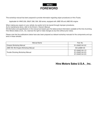
1. FOREWORD
This workshop manual has been prepared to provide information regarding repair procedures on Hino Trucks.
Applicable for HINO 238, 258LP, 268, 338, 358 series, equipped with J08E-VB and J08E-WU engine
When making any repairs on your vehicle, be careful not to be injured through improper procedures.
As for maintenance items, refer to the Driver’s / Owner’s Manual.
All information and specifications in this manual are based upon the latest product information available at the time of printing.
Hino Motors Sales U.S.A., Inc. reserves the right to make changes at any time without prior notice.
Please note that the publications below have also been prepared as relevant workshop manuals for the components and sys-
tems in these vehicles.
Manual Name Pub. No.
Chassis Workshop Manual S1-UNAE14A 2/2
J08E-VB, WU Engine Workshop Manual S5-UJ08E14A
Trouble Shooting Workshop Manual
S7-UNAE14A 1/3
S7-UNAE14A 2/3
S7-UNAE14A 3/3
MENU
2. CHAPTER REFERENCES REGARDING THIS WORKSHOP MANUAL
Use this chart to the appropriate chapter numbers for servicing your particular vehicle.
CHAPTER
MANUAL NO. S1-UNAE14A 1/2 (U.S.A.), S1-CNAE14A 1/2 (CANADA)
MODELS HINO 238, 258LP, 268, 338, 358
Production Model
Code
NE8J, NF8J, NJ8J, NV8J, NH8J
GENERAL INTRODUCTION GN02-001
CLUTCH MAIN UNIT CL02-001
CLUTCH CONTROL CL03-001
TRANSMISSION MAIN UNIT TR02-001
AUTOMATIC TRANSMISSION TR04-001 TR04-002
TRANSMISSION/TRANSFER CONTROL TR06-001 TR06-002
PROPELLER SHAFT PP02-001
DIFFERENTIAL CARRIER DF02-001
BRAKE EQUIPMENT BR01-001 BR01-002
SERVICE BRAKE BR02-001 BR02-002
ABS (ANTI-LOCK BRAKE SYSTEM) BR03-001 BR03-002
EXHAUST BRAKE BR05-001
PARKING BRAKE BR07-001
STEERING EQUIPMENT SR01-001
STEERING UNIT SR02-001
POWER STEERING SR03-001
FRONT AXLE AX02-001
REAR AXLE AX03-001
WHEEL & TIRE AX04-001
SUSPENSION SU02-001
CHASSIS FRAME FC02-001
CAB CA02-001
ELECTRICAL EQUIPMENT EL01-001
ELECTRIC WIRE EL02-001
This manual does not contain items on half-tone dot meshing.
3. CLUTCH EQUIPMENT
CLUTCH MAIN UNIT
CLUTCH CONTROL
TRANSMISSION EQUIPMENT
TRANSMISSION MAIN UNIT
TRANSFER MAIN UNIT
AUTOMATIC TRANSMISSION
PTO (POWER TAKE-OFF)
TRANSMISSION / TRANSFER CONTROL
PROPELLER SHAFT
DIFFERENTIAL EQUIPMENT
DIFFERENTIAL CARRIER
INDEX: CHASSIS GROUP 1/4
PROPELLER SHAFT EQUIPMENT
BRAKE EQUIPMENT
SERVICE BRAKE
ABS
GENERAL INTRODUCTION
WORKSHOP
MANUAL
4. ES START (EASY & SMOOTH START) SYSTEM
EXHAUST BRAKE
RETARDER BRAKE
PARKING BRAKE
STEERING EQUIPMENT
STEERING UNIT
INDEX: CHASSIS GROUP 2/4
POWER STEERING
AXLE EQUIPMENT
FRONT AXLE
REAR AXLE
WHEEL & TIRE
SUSPENSION EQUIPMENT
SUSPENSION
CHASSIS EQUIPMENT
CHASSIS FRAME
COUPLER (5TH WHEEL)
PINTLE HOOK
7. GENERAL INTRODUCTION (CHASSIS) GN02–1
GN02GENERAL INTRODUCTION (CHASSIS) GN02-001
GENERAL INTRODUCTION.....................GN02-2
GENERAL PRECAUTIONS.............................GN02-2
IDENTIFICATION INFORMATION...................GN02-5
HOW TO USE
THIS WORKSHOP MANUAL.........................GN02-13
PRECAUTIONS .............................................GN02-16
SEALANT ON THE TAPERED SCREW
FOR PIPING ..................................................GN02-19
NYLON TUBE REPLACEMENT METHOD ...GN02-20
METRIC INFORMATION ...............................GN02-22
SPECIFIED TORQUE
FOR STANDARD BOLTS AND NUTS ...........GN02-24
SPECIFIED TORQUE
FOR FLANGE BOLTS AND NUTS ................GN02-24
RECOMMENDED LUBRICANTS ..................GN02-26
VEHICLE LIFT
AND SUPPORT LOCATIONS........................GN02-28
INFORMATION DISPLAY ..............................GN02-30
SYMPTOM SIMULATION ..............................GN02-35
GLOSSARY................................................... GN02-37
GLOSSARY OF SAE AND HINO TERMS.....GN02-40
8. GENERAL INTRODUCTION (CHASSIS)GN02–2
GENERAL INTRODUCTION
GENERAL PRECAUTIONS
EN00Z08020100001
Some recommended and standard maintenance services for your vehicle are included in this section. When performing main-
tenance on your vehicle be careful not to get injured by improper work. Improper or incomplete work can cause a malfunction
of the vehicle which may result in personal injury and/or property damage. If you have any question about performing mainte-
nance, please consult your Hino dealer.
DEFINITION OF SAFETY TERMS
WARNING
When working on your vehicle, observe the following general precautions to prevent death, personal injury and/or
property damage in addition to the particular DANGERS, WARNINGS, CAUTIONS and NOTICES in each chapter.
• Always wear safety glasses or goggles to protect your eyes.
• Remove rings, watches, ties, loose hanging jewelry and loose clothing before starting work on the vehicle.
• Bind long hair securely behind the head.
• When working on the vehicle, apply the parking brake firmly, place the gear shift lever in "Neutral" or "N" and
block the wheels.
• Always turn off the starter switch to stop the engine, unless the operation requires the engine running. Remov-
ing the key from the switch is recommended.
• To avoid serious burns, keep yourself away from hot metal parts such as the engine, exhaust manifold, radia-
tor, muffler, exhaust pipe and tail pipe.
• Do not smoke while working on the vehicle since fuel, and gas from battery are flammable.
• Take utmost care when working on the battery. It contains corrosive sulfuric acid.
• Large electric current flows through the battery cable and starter cable. Be careful not to cause a short which
can result in personal injury and/or property damage.
• Read carefully and observe the instructions specified on the jack before using it.
• Use safety stands to support the vehicle whenever you need to work under it. It is dangerous to work under a
vehicle supported only by a jack.
• If it is necessary to run the engine after the hood is raised (tilted), make sure that the parking brake is firmly
applied, the wheels are blocked, and the gear shift lever is positioned in "Neutral" before staring the engine.
• Run the engine only in a well-ventilated area to avoid inhalation of carbon monoxide.
• Keep yourself, your clothing and your tools away from moving parts such as the cooling fan and V-belts when
the engine is running.
• Be careful not to damage lines and hoses by stepping or holding your feet on them.
• Be careful not to leave any tool in the engine compartment. The tool may be hit by moving parts, which can
cause personal injury.
Indicates an extremely hazardous situation if proper procedures are not followed and could
result in death or serious injury.
Indicates a potential hazardous situation if proper procedures are not followed and could
result in death or serious injury.
Indicates a hazardous situation if proper procedures are not followed and could result in
serious injury or damage to parts/equipment.
Indicates the need to follow proper procedures and to pay attention to precautions so that
efficient service is provided.
Provides additional information to help you to perform the repair efficiently.
9. GENERAL INTRODUCTION (CHASSIS) GN02–3
TOWING
• When being towed, always place the gear shift lever in "Neutral" and release the parking brake completely. In order to
protect the bumper, fit a protection bar against the lower edge of the bumper and put a wood block under the frame near
the No. 1 cross member when attaching the towing chain. Never lift or tow the vehicle if the chain is in direct contact with
the bumper.
1. Towing procedures
(1) Make sure that the propeller shaft of the vehicle to be towed is removed. When the differential gear or rear axle shaft is
defective, remove both right and left rear axle shafts, then cover the hub opening to prevent loss of axle lubricant and
entry of dirt or foreign matter.
(2) Use a heavy duty cable or rope when towing the vehicle. Fasten the cable securely to the towing hook on the frame.
(3) The angle of pulling direction of the cable fastened to the towing hook must not exceed 15 in horizontal and vertical
directions from the straight ahead, level direction. Avoid using the hook in a way that subjects it to jerk, as in towing a
vehicle trapped in a gutter.
(4) Keep the gear shift lever in Neutral.
(5) Make sure that the starter switch is kept in the "ON" position, if the engine is not running.
(6) Make sure that the engine of the towed vehicle is kept running. If the engine is off, no compressed air/ no vacuum will be
available for the brake. This is dangerous, as the brake system does not function if the engine is not running.
In addition, the power steering system will not function. The steering wheel, therefore, will become unusually hard to turn,
making it impossible to control the vehicle.
(7) Note that the engine brake and exhaust brake cannot be applied, if the propeller shaft is removed.
(8) Make a slow start to minimize shock. Towing speed should be less than 30 km/h {18 mile/h}.
2. If the engine of the towed vehicle is defective, make sure that the vehicle is towed only by a tow truck designed
for that purpose.
(1) Front end towing (with front wheels raised off the ground)
When towing from the front end with the front wheels raised off the ground, remove the rear axle shafts to protect the
transmission and differential gears from being damaged. The hub openings should be covered to prevent the loss of axle
lubricant or the entry of dirt or foreign matter. The above-mentioned precautions should be observed for vehicles
equipped with either manual or automatic transmission, and for even short distance towing. After being towed, check and
refill the rear axle housing with lubricant if necessary.
(2) Rear end towing
When being towed with the rear wheels raised off the ground, fasten and secure the steering wheel in a straight-ahead
position.
CLEAN AIR ACT
1. Heavy-duty engine rebuilding practices.
§ 86.004-40
• The provisions of this section are applicable to heavy-duty engines subject to model year 2004 or later standards and are
applicable to the process of engine rebuilding (or rebuilding a portion of an engine or engine system). The process of
engine rebuilding generally includes disassembly, replacement of multiple parts due to wear, and reassembly, and also
may include the removal of the engine from the vehicle and other acts associated with rebuilding an engine. Any deviation
from the provisions contained in this section is a prohibited act under section 203(a) (3) of the Clean Air Act (42 U.S.C.
7522(a) (3)).
(1) When rebuilding an engine, portions of an engine, or an engine system, there must be a reasonable technical basis for
knowing that the resultant engine is equivalent, from an emissions standpoint, to a certified configuration (i.e., tolerances,
calibrations, specifications) and the model year(s) of the resulting engine configuration must be identified. A reasonable
basis would exist if:
a. Parts installed, whether the parts are new, used, or rebuilt, are such that a person familiar with the design and func-
tion of motor vehicle engines would reasonably believe that the parts perform the same function with respect to emis-
sions control as the original parts; and
b. Any parameter adjustment or design element change is made only:
In accordance with the original engine manufacturer's instructions; or
Where data or other reasonable technical basis exists that such parameter adjustment or design element change,
when performed on the engine or similar engines, is not expected to adversely affect in-use emissions.
(2) When an engine is being rebuilt and remains installed or is reinstalled in the same vehicle, it must be rebuilt to a configu-
ration of the same or later model year as the original engine. When an engine is being replaced, the replacement engine
must be an engine of (or rebuilt to) a configuration of the same or later model year as the original engine.
10. GENERAL INTRODUCTION (CHASSIS)GN02–4
(3) At time of rebuild, emissions-related codes or signals from on-board monitoring systems may not be erased or reset with-
out diagnosing and responding appropriately to the diagnostic codes, regardless of whether the systems are installed to
satisfy requirements in § 86.004-25 or for other reasons and regardless of form or interface. Diagnostic systems must be
free of all such codes when the rebuilt engine is returned to service. Such signals may not be rendered inoperative during
the rebuilding process.
(4) When conducting a rebuild without removing the engine from the vehicle, or during the installation of a rebuilt engine, all
critical emissions-related components listed in § 86.004-25(2) not otherwise addressed by paragraphs (1) through (3) of
this section must be checked and cleaned, adjusted, repaired, or replaced as necessary, following manufacturer recom-
mended practices.
(5) Records shall be kept by parties conducting activities included in paragraphs (1) through (4) of this section. The records
shall include at minimum the mileage and/or hours at time of rebuild, a listing of work performed on the engine and emis-
sions-related control components including a listing of parts and components used, engine parameter adjustments, emis-
sions-related codes or signals responded to and reset, and work performed under paragraph (4) of this section.
a. Parties may keep records in whatever format or system they choose as long as the records are understandable to an
EPA enforcement officer or can be otherwise provided to an EPA enforcement officer in an understandable format
when requested.
b. Parties are not required to keep records of information that is not reasonably available through normal business prac-
tices including information on activities not conducted by themselves or information that they cannot reasonably
access.
c. Parties may keep records of their rebuilding practices for an engine family rather than on each individual engine
rebuilt in cases where those rebuild practices are followed routinely.
d. Records must be kept for a minimum of two years after the engine is rebuilt.
2. Maintenance instructions.
§ 86.010-38
(1) For each new diesel-fueled engine subject to the standards prescribed in § 86.007-11, as applicable, the manufacturer
shall furnish or cause to be furnished to the ultimate purchaser a statement that
"This engine must be operated only with ultra low-sulfur diesel fuel (meeting EPA specifications for highway die-
sel fuel, including a 15 ppm sulfur cap)."
11. GENERAL INTRODUCTION (CHASSIS) GN02–13
HOW TO USE THIS WORKSHOP MANUAL
EN00Z08020200002
This workshop manual is designed as a guide for servicing the vehicle.
An INDEX is provided on the first page of each chapter.
TROUBLESHOOTING is dealt with in each chapter.
When beginning operations, refer to the TROUBLESHOOTING section for
a guide to appropriate diagnosis.
SPECIAL TOOL is dealt with in each chapter.
When ordering a special tool, confirm the part number with the applicable
parts catalog.
• RERAIR PROCEDURES
Repair procedures when self-explanatory, such as simple installation
and removal of parts, have been omitted. Illustrations, such as the
one below, have been provided to make such simple procedures
clear. Only essential procedures requiring specific directions have
been dealt with explicitly.
12. GENERAL INTRODUCTION (CHASSIS)GN02–14
MAIN CYLINDER
EXAMPLE:
Tightening torque Unit: Nm {kgfcm, lbfft}
In some cases, illustrations may be of parts which differ in some nonessen-
tial way from the parts found on your particular vehicle. In such cases, the
principle or procedure being illustrated applies regardless of such nones-
sential differences.
• DEFINITION OF TERMS
Definition of vehicle right and left.
Right and left refers to the left and right sides of the vehicle as seen
while looking down the center line from the rear towards the front.
SAPH00Z080200014
1 Clevis 8 Return spring
2 Lock nut 9 Body
3 Push rod 10 Hose joint
4 Boot 11 O-ring
5 Retainer ring 12 Soft washer
6 Thrust washer 13 Bolt
7 Piston
A 2.5-4.4 {25-45, 1.8-3.2}
14. CLUTCH MAIN UNIT (EATON 1402) CL02–7
OVERHAUL
EN02Z0202H200001
IMPORTANT POINT - DISMOUNTING
1. REMOVE THE TRANSMISSION, SUPPORTING ITS WEIGHT TO
PREVENT DAMAGE TO THE BEARING AND DISCS.
2. INSTALL TWO WOODEN SPACERS 1"-1-1/2" THICK BETWEEN
RELEASE BEARING AND COVER ASSEMBLY.
3. REMOVE THE CLUTCH FROM THE FLYWHEEL.
IMPORTANT POINT - INSPECTION AND REPLACE-
MENT
1. REPLACE THE PILOT BEARING.
(1) Remove the pilot bearing.
SST:
Pilot Bearing Puller (S0965-01970)
Sliding Hammer (S0942-01442)
(2) Using a suitable tapping rod, install the pilot bearing.
NOTICE
After installing the pilot bearing, ensure that it rotates smoothly.
2. CHECK THE FOLLOWING ITEMS FOR WEAR REPLACE ANY
WORN COMPONENTS:
(1) Cross-shafts and bushings
NOTICE
Excessive wear at these points can cause a side loading condition.
Also, inspect the remaining pivot points of the linkage for excessive
wear.
1.
Remove the
transmission
SAPH02Z020200007
SAPH02Z020200008
SAPH02Z020200009
A.
Check cross-shafts
and bushings
SAPH02Z020200010
15. CLUTCH MAIN UNIT (EATON 1402)CL02–8
(2) Release yoke fingers
(3) Splines on the input shaft
NOTICE
Any wear on the splines will prevent the newly installed driven discs
from sliding freely, thus causing poor release (clutch drag). Select a
disc out of the new installation and slide it full length on the transmis-
sion splines. This will detect a twisted input shaft. Replace input shaft
if disc does not freely slide.
(4) Smooth area of input shaft
(5) Mating surfaces
NOTICE
Inspect the mating surfaces of both the transmission bell housing and
the flywheel housing. Any appreciable wear on either housing will
cause misalignment. Most wear will occur between the 3 and 8 o'clock
positions.
Replace housings if worn.
B.
Check release yoke
fingers
SAPH02Z020200011
D.
Check splines on the
input shaft
SAPH02Z020200012
E.
Check smooth
area of input
shaft for wear /
roughness
SAPH02Z020200013
16. CLUTCH MAIN UNIT (EATON 1402) CL02–9
IMPORTANT POINT - MOUNTING
1. INSERT TWO (2) 3/8" x 16 UNC x 3" (76 MM) LONG GUIDE STUDS
INTO THE TWO UPPER MOUNTING HOLES OF THE FLYWHEEL.
2. INSTALL THE FRONT DISC BY INSERTING THE ALIGNING TOOL
THROUGH THE DISC SPLINES AND THEN INTO THE PILOT
BEARING.
SST:
Clutch Aligning Arbor (S0966-21420)
NOTICE
Make sure the side marked "Flywheel" faces the flywheel.
3. INSTALL THE INTERMEDIATE PLATE ASSEMBLY OVER THE
TWO (2) GUIDE STUDS AND SLIDE IT FORWARD UNTIL IT
TOUCHES THE FLYWHEEL.
NOTICE
Make sure the side marked "Pressure Plate Side" is facing the pres-
sure plate (the drive straps must face the pressure plate).
1.
Insert 2 guide studs
Guide studs
SAPH02Z020200014
2.
Insert the aligning
tool through release
bearing sleeve
Aligning tool
SAPH02Z020200015
3.
Place intermediate
plate properly
orientated
SAPH02Z020200016
17. CLUTCH MAIN UNIT (EATON 1402)CL02–10
4. REMOVE THE ALIGNING TOOL AND INSTALL IT THROUGH THE
SPLINES OF THE REAR DISC, AND INSERT THE ALIGNING
TOOL THROUGH THE FRONT DISC AND ALSO THE PILOT
BEARING.
NOTICE
Make sure the side of the disc marked "Pressure Plate Side" is facing
the pressure plate. As you complete this step, ensure that the ceramic
buttons align with each other as closely as possible. Doing so will aid
the function of the positive separator pins (roll pins).
5. WITH THE ALIGNING TOOL STILL IN PLACE, SLIDE THE COVER
ASSEMBLY OVER BOTH THE ALIGNING TOOL AND THE TWO (2)
GUIDE STUDS UNTIL IT RESTS AGAINST THE INTERMEDIATE
PLATE ASSEMBLY.
4.
Remove aligning tool
Buttons
SAPH02Z020200017
5.
Slide cover assembly
over aligning tool
and guide studs
SAPH02Z020200018
18. CLUTCH MAIN UNIT (EATON 1402) CL02–11
6. INSTALL LOCKWASHER AND SIX (6) 3/8" x 16 UNC MOUNTING
BOLTS HAND TIGHTEN.
(1) Remove the two (2) guide studs and replace with the remaining
mounting bolts with lockwasher. Using a torque wrench, progressively
tighten the eight (8) mounting bolts using the following criss-cross pat-
tern. Starting at lower left.
Tightening Torque:
50-64 Nm {510-665 kgfcm, 37-47 lbfft}
! CAUTION
Failure to tighten these bolts in this manner can:
• Prevent the clutch cover from "centering" into the pilot area of
the flywheel.
• Cause permanent damage to the clutch cover (i.e. become
cracked or broken).
• Cause the clutch assembly to be out-of balance with the fly-
wheel.
7. REMOVE THE ALIGNING TOOL.
8. USING A 1/4" (6 mm) DIAMETER FLAT NOSE PUNCH, LIGHTLY
TAP EACH OF THE FOUR (4) POSITIVE SEPARATOR PINS
TOWARD THE FLYWHEEL. PERFORMING THIS STEP WILL VER-
IFY THAT ALL FOUR (4) PINS ARE FLUSH AGAINST THE FLY-
WHEEL.
! CAUTION
Failure to perform this step properly may cause the clutch to drag
(clutch does not release). Excessive force can damage the pins and
cause a release problem
NOTICE
The four (4) pins can also be set through the inspection opening of
the transmission bell housing if they were not to set prior to transmis-
sion installation.
8
1
5
3
7
2
6
4
6.
Place disc on aligning
tool properly orientated
SAPH02Z020200019
7.
Remove aligning tool
SAPH02Z020200020
SAPH02Z020200021
19. CLUTCH MAIN UNIT (EATON 1402)CL02–12
9. SHIFT THE TRANSMISSION INTO GEAR.
10. POSITION THE TRANSMISSION SO THAT IT IS BOTH SQUARE
TO AND ALIGNED WITH THE ENGINE.
Top view
Roll pin
Clutch cover
Access hole
SAPH02Z020200022
Side view
Gap
0.20"-0.30"
(0.5-0.8mm)
Flywheel
Clutch cover
Roll pin (Qty.4)
Access hole
SAPH02Z020200023
9.
Shift transmission into gear
Shift into gear
SAPH02Z020200024
10.
Align the transmission
to the engine
SAPH02Z020200025
20. CLUTCH MAIN UNIT (EATON 1402) CL02–13
11. WHILE MOVING THE TRANSMISSION FORWARD, ROTATE THE
OUTPUT SHAFT OF THE TRANSMISSION UNTIL THE SPLINES
OF BOTH THE INPUT SHAFT AND THE DISC(S) MESH WITH
EACH OTHER. WHILE PERFORMING THIS TASK, YOU MUST
ALSO ENSURE THAT THE YOKE FINGERS REMAIN IN THE UP
POSITION UNTIL THEY CAN BE ROTATED OVER THE RELEASE
BEARING HOUSING INTO THEIR FINAL POSITION.
! CAUTION
• Do not use the cross-shaft release lever (or a pipe over it) to pull
the transmission into its final position.
• Do not excessively force the transmission into the clutch assem-
bly or engine housing. If it does not enter freely, investigate the
cause of the problem and make any necessary changes.
• If the input shaft will not slide into the discs, they may need to be
repositioned. Do not let the transmission drop or hang unsup-
ported in the driven discs.
This can cause the discs to become distorted and the clutch will
not release.
12. INSTALL THE TRANSMISSION MOUNTING BOLTS AND TORQUE
TO THE PROPER SPECIFICATION.
Tightening Torque:
37.5-48.5 Nm {382-494 kgfcm, 28-35 lbfft}
IMPORTANT POINT - ADJUSTMENT
1. CHECK LOCATION OF THE KWIK-ADJUSTER
(1) Remove the cover of inspection hole at the bottom of the clutch hous-
ing.
(2) If the Kwik-Adjuster exists in approachable position, adjustment can
be performed.
If position of the Kwik-Adjuster cannot be identified, perform following
procedure.
11.
Mesh input shaft and
disc (s) by rotating
output shaft
SAPH02Z020200026
SAPH02Z020200027
Socket wrench
Kwik-adjuster
SAPH02Z020200028
21. CLUTCH MAIN UNIT (EATON 1402)CL02–14
2. ARRANGE THE KWIK-ADJUSTER
(1) Set SST the crank pulley.
SST:
Cranking Tool (S0940-91200)
(2) Turn the crank pulley till the Kwik-Adjuster matches the inspection
hole.
3. ADJUSTING PROCEDURES
(1) Adjust the release bearing position;
• When the clutch disc is worn (pedal play less than limit)
Pedal play limit; 35 mm {1.38 in.}
• When the clutch disc replaced.
(2) Adjust the free travel by release cylinder push rod only;
• When the clutch disc or control linkage is replaced.
NOTICE
The above adjusting should be made after adjusting the release bear-
ing position.
(3) Manual Adjust: Kwik-Adjust
• Depress adjusting bolt and rotate.
Kwik-Adjust will re-engage at 1/3 of a turn.
NOTICE
• Open-end wrenches are not recommended.
• Internal adjustments are performed with pedal down (clutch
released).
SST
Crank pulley
Torque
wrench
SAPH02Z020200029
Kwik-adjuster
SAPH02Z020200030
1 STEP: Master cylinder
push rod play
2 STEP:
Release cylinder
push rod play
Clutch pedal play
SAPH02Z020200031
Adjusting
bolt (push
toward
clutch)
Kwik-
adjust
SAPH02Z020200032
22. CLUTCH MAIN UNIT (EATON 1402) CL02–15
4. ADJUST THE RELEASE BEARING POSITION
(1) Set 0.75" (19 mm) dimension: With pedal down, turn adjusting ring to
obtain approximately 0.75" (19 mm). Turning the adjusting ring clock-
wise moves the release bearing toward the transmission. Turning the
adjusting ring counterclockwise moves the release bearing toward the
engine.
(2) Check release travel dimensions with release yoke rotated toward
release bearing, eliminating excess play in system. Having set this,
depress pedal down fully releasing clutch and check release travel to
settings shown.
NOTICE
It may be necessary to reduce the 0.75" (19 mm) settings to be able to
achieve 0.500"-0.562" (13-14 mm) travel on some models of transmis-
sions.
5. ADJUST THE FREE TRAVEL
(1) Remove the return spring.
(2) Loosen the lock nut and turn the push rod counterclockwise until the
release bearing contacts the release lever plate or release lever.
(3) Turn the push rod clockwise about 3 1/3 turns.
(4) Tighten the lock nut.
0.75" (19mm)
Clutch
Transmission
MIN. 1.25
(32mm)
MAX. 1.32
(33mm)
Pedal
UP
Pedal
DOWN
SAPH02Z020200033
Master cylinder
Push rod
0
SAPH02Z020200034
Lock nut
3.18
SAPH02Z020200035
Standard: Clearance between release bearing and
release yoke: 3.18 mm {0.125 in.}
23. CLUTCH MAIN UNIT (EATON 1402)CL02–16
CLUTCH ASSEMBLY (EATON SOLO1402)
DATA AND SPECIFICATIONS
EN02Z0202I200002
CLUTCH FACING Unit: mm {in.}
COMPONENT LOCATOR
EN02Z0202D100002
Tightening torque Unit: Nm {kgfcm, lbfft}
Material Sintered metal (Ceramic metal)
Type Dry two plate with damper spring
Inside diameter 222 {8.8}
Outside diameter 350 {13.8}
Thickness 11.5 {0.45} Adjustment-Free
1 Clutch cover 3 Intermediate plate
2 Clutch disc 4 Bolt
A 37.5-48.5 {383-494, 28-35}
Wear indicator
Shipping bolts (4)
to be removed
at installation
SAPH02Z020200036
24. Thank you very much for
your reading. Please Click
Here. Then Get COMPLETE
MANUAL. NO WAITING
NOTE:
If there is no response to
click on the link above,
please download the PDF
document first and then
click on it.
25. CLUTCH MAIN UNIT (EATON 1402) CL02–17
OVERHAUL
EN02Z0202H200002
IMPORTANT POINT - DISMOUNTING
1. REMOVE THE TRANSMISSION, SUPPORTING ITS WEIGHT TO
PREVENT DAMAGE TO THE BEARING AND DISCS.
NOTICE
If a SOLO Clutch is to be removed and reinstalled on the flywheel, four
(4) shipping bolts must be installed prior to unbolting the clutch (3/8"
x 16 UNC x 1-1/4").
2. LOCATE FOUR (4) 3/8" x 16 x 1 - 1/4" UNC, HEX HEAD MACHINE
SCREWS. INSTALL THEM IN THE 4 COVER HOLES, TURNING
THEM ONE COMPLETE TURN AFTER THEY CONTACT THE
COVER.
3. REMOVE THE CLUTCH FROM THE FLYWHEEL.
NOTICE
Mark the proper position of the discs and intermediate plate adapter
ring (for reinstallation).
IMPORTANT POINT - INSPECTION AND REPLACE-
MENT
1. REPLACE THE PILOT BEARING.
(1) Remove the pilot bearing.
SST:
Pilot Bearing Puller (S0965-01970)
Sliding Hammer (S0942-01442)
1.
Remove the
transmission
SAPH02Z020200037
2.
Located 4 hex head
machine screws
(4) 3/8" x 16 x 1-1/4" UNC
SAPH02Z020200038
SAPH02Z020200039
26. CLUTCH MAIN UNIT (EATON 1402)CL02–18
(2) Using a suitable tapping rod, install the pilot bearing.
NOTICE
After installing the pilot bearing, ensure that it rotates smoothly.
2. CHECK THE FOLLOWING ITEMS FOR WEAR REPLACE ANY
WORN COMPONENTS:
(1) Cross-shafts and bushings
NOTICE
Excessive wear at these points can cause a side loading condition.
Also, inspect the remaining pivot points of the linkage for excessive
wear.
(2) Release yoke fingers
(3) Splines on the input shaft
NOTICE
Any wear on the splines will prevent the newly installed driven discs
from sliding freely, thus causing poor release (clutch drag). Select a
disc out of the new installation and slide it full length on the transmis-
sion splines. This will detect a twisted input shaft. Replace input shaft
if disc does not freely slide.
SAPH02Z020200040
A.
Check cross-shafts
and bushings
SAPH02Z020200041
B.
Check release yoke
fingers
SAPH02Z020200042
D.
Check splines on the
input shaft
SAPH02Z020200043
27. CLUTCH MAIN UNIT (EATON 1402) CL02–19
(4) Smooth area of input shaft
(5) Mating surfaces
NOTICE
Inspect the mating surfaces of both the transmission bell housing and
the flywheel housing. Any appreciable wear on either housing will
cause misalignment. Most wear will occur between the 3 and 8 o'clock
positions.
Replace housings if worn.
IMPORTANT POINT - MOUNTING
1. INSERT TWO (2) 3/8" x 16 UNC x 3" (76 MM) LONG GUIDE STUDS
INTO THE TWO UPPER MOUNTING HOLES OF THE FLYWHEEL.
2. INSTALL THE FRONT DISC BY INSERTING THE ALIGNING TOOL
THROUGH THE DISC SPLINES AND THEN INTO THE PILOT
BEARING.
SST:
Clutch Aligning Arbor (S0966-21420)
NOTICE
Make sure the side marked "Flywheel" faces the flywheel.
E.
Check smooth
area of input
shaft for wear /
roughness
SAPH02Z020200044
1.
Insert 2 guide studs
Guide studs
SAPH02Z020200045
2.
Insert the aligning
tool through release
bearing sleeve
Aligning tool
SAPH02Z020200015
28. CLUTCH MAIN UNIT (EATON 1402)CL02–20
3. INSTALL THE INTERMEDIATE PLATE ASSEMBLY OVER THE
TWO (2) GUIDE STUDS AND SLIDE IT FORWARD UNTIL IT
TOUCHES THE FLYWHEEL.
NOTICE
Make sure the side marked "Pressure Plate Side" is facing the pres-
sure plate (the drive straps must face the pressure plate).
4. REMOVE THE ALIGNING TOOL AND INSTALL IT THROUGH THE
SPLINES OF THE REAR DISC, AND INSERT THE ALIGNING
TOOL THROUGH THE FRONT DISC AND ALSO THE PILOT
BEARING.
NOTICE
Make sure the side of the disc marked "Pressure Plate Side" is facing
the pressure plate. As you complete this step, ensure that the ceramic
buttons align with each other as closely as possible. Doing so will aid
the function of the positive separator pins (roll pins).
3.
Place intermediate
plate properly
orientated
SAPH02Z020200046
4.
Remove aligning tool
Buttons
SAPH02Z020200017