5. 4
SECTION NINE
CHASSIS
SECTION TEN
ATTACHMENTS
ROLL OVER PROTECTION STRUCTURE (ROPS) .....................................10 - 2
ROPS TIGHTENING TORQUES ........................................................ 10 - 2
6. July 2004 1 - 1
SECTION ONE
GENERAL INFORMATION
7. SM96106 - SECTION ONE GENERAL INFORMATION
July 2004 1 - 3
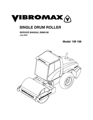
MACHINE DESCRIPTION
This book introduces the new
Vibromax 6 series single drum
rollers. Included within the pag-
es of the book are materials
covering the Model VM106.
The new roller uses the Cum-
mins 3.9 liter 4 cylinder engine.
The engine is turbocharged
and tuned to meet the latest
EPA emissions standards.
A Mannesman Rexroth vari-
able displacement, axial piston
hydrostatic pump, used for ma-
chine propulsion, is mounted to
the flywheel end of the engine.
It provides oil to a Rexroth 2
speed drum drive motor and a
2 speed axle drive motor in a
parallel path. The Rexroth
drum motor is mounted on the
left side of the drum, drives
through a L&S planetary gear-
box and is isolated from the
drum by rubber buffers. This ar-
rangement is used in the heavy
roller models with a great deal
of success. The axle drive mo-
tor is attached directly to the in-
termediate gearbox
incorporated into the rear axle.
8. SM96106 - SECTION ONE GENERAL INFORMATION
1 - 4 July 2004
The vibration system on the VM106 uses a
Rexroth hydrostatic pump mounted directly
behind the propulsion pump. It is similar in
design to the propulsion pump. The vibrato-
ry pump supplies oil to a Rexroth hydrostat-
ic motor mounted at the right side of the
drum. This operates at frequencies of 1860
or 2160 vibrations per minute on both the
smooth drum and pad foot versions.
A steering pump, mounted to the rear of the
vibratory pump, provides the oil needed for
steering. The steering pump also acts as
the charge pump in the propulsion and vi-
bration systems. The steering pump draws
oil from the reservoir, passes it through the
steering control valve, through the inline hy-
draulic filter, and into the charge circuit.
This machine comes standard with parking
brakes at both the front drum and the rear
axle. A spring applied-hydraulically re-
leased multi disc brake is part of the drum
drive motor gearbox. The axle uses a spring
applied hydraulically released multiple disc
brake at each axle shaft.
Pressure testing has been made easier by
placing all the test ports at a centrally locat-
ed test station under the engine hood.
The electrical system consists of a 12 volt
battery, starter, alternator system, optional
lighting and standard instrumentation.
9. SM96106 - SECTION ONE GENERAL INFORMATION
July 2004 1 - 5
SERIAL NUMBERS
1 Model / Serial Number
2 Front Drum Drive Motor S/N
3 Steering Unit S/N
4 Axle S/N
5 Vibratory Motor S/N
6 Hydraulic Pumps S/N
7 Axle Drive Motor S/N
8 Engine S/N
10. SM96106 - SECTION ONE GENERAL INFORMATION
1 - 6 July 2004
IDENTIFYING MACHINE COMPONENTS
1 Articulation joint 11 Isolation buffer
2 Smooth drum 12 Scraper
3 Lifting and towing eyes 13 Engine exhaust
4 Operator’s platform 14 Fuel tank
5 Battery 15 Cooling system
6 Hydraulic tank 16 Vibration motor
7 Engine 17 Steering cylinder
8 Axle 18 Hydraulic pumps
9 Air filter 19 Axle drive motor
10 Drum drive motor
11. Thank you very much for
your reading. Please Click
Here. Then Get COMPLETE
MANUAL. NO WAITING
NOTE:
If there is no response to
click on the link above,
please download the PDF
document first and then
click on it.
12. SM96106 - SECTION ONE GENERAL INFORMATION
July 2004 1 - 7
FLUID SPECIFICATIONS
MACHINE PART
CAPACITY USA
(metric)
SPECIFICATIONS
Fuel tank 79.3 gal (300 l) see diesel fuel
Engine
crankcase
11.5 qts(11.0 l) engine oil
API classification API-CI-4
multigrade engine oil (see oil chart)
Hydraulic system
Reservoir only
21.1 gal (80 l)
15.9 gal (60 l)
cold weather HLP 46 DIN 51524/2
hot weather HLP 68 DIN 51524/2
Mobil DTE 25,26
Shell Tellus OL 46,68
Amoco Rykon HD 46,68
Texaco Rando HD 46,68
Input Gearbox
Differential gear
Planetary (each)
1.8 qts (1.75 l)
10.0 qts (9.5 l)
2.1 qts (2.0 l)
SAE 90 API GL-5 gear lubricant
Alternate
SAE 85/140 API GL-5 gear lubricant
Drum gearbox 1.4 qts (1.3 l) CLP 220 LS 2 DIN 51517/3
Mobilgear 630
Mobilgear SHC 220
Texaco Syngear 220
Vibration system 3.7 qts (3.5 l) CLP 150 DIN 51517/3
Mobil Gear 629
Shell Omala 150
Texaco Meropa 150
Battery as required Distilled water
Grease as required KP3K DIN 51502
Mobil Oil - Mobilux 3
Shell Oil - Alvania 3
Texaco Oil - Starplex 3
Engine coolant 14.8 qts (14 l) 50% ethylene glycol and 50% water
-34 degrees F (-37 degrees C)
Tire ballast see tire ballast Calcium Chloride (77%CaCl2
)
13. SM96106 - SECTION ONE GENERAL INFORMATION
1 - 8 July 2004
MACHINE SPECIFICATIONS
MODEL VM106
in. mm
a 112.0 2846
b 88.6 2250
c 60.0 1523
d1 59.8 1520
d2 59.1 1500
d3 55.1 1400
d4 63 1600
h 115.6 2935
h1 86.0 2185
k 17.6 447
l 214.3 5444
o 3 75
s 1 25
w 82.7 2100
e1 41 degrees
e2 32 degrees
14. SM96106 - SECTION ONE GENERAL INFORMATION
July 2004 1 - 9
ENGINE Make/Model/Type/Displacement - cu. in. (cc)
HP, SAE net (kW) @2200 rpm
Air Cleaner / Fuel filter
Fuel capacity - gal (ltr)
Cummins 3.9 125C, 4 cylinder turbo diesel (water cooled), 239 cu.in. (3920cc)
with charge air cooler
125 (93)
Dual replaceable elements, Spin-on cartridge
79.3 (300)
VM106D VM106PD
Operating weight max. -lb (kg) 24912 (11300) 25574 (11600)
Weight, front-lb (kg) 13228 (6000) 13889 (6300)
Weight, rear axle - lb (kg) 11684 (5300) 11684 (5300)
Static applied linear drum load lb/in (kg/cm) 160 (28.6) -----------
Articulation/oscillation-degrees 35/15 35/15
Turning radius-inside-ft. (m) 11.16 (3.4) 11.16 (3.4)
Drum shell thickness-in. (mm) 1.0 (25) 1.0 (25)
Number of pad feet/height of foot - in. (mm) 132/ 3.9 (100)
Contact area of foot-sq. in. (cm) 64 sq.in.(413 sq. cm)
Tire size 23.1 - 26 8PR diamond tread 23.1 - 26 8PR tractor tread
Travel speed - 1st range mph (km/hr) 0 - 2.8 (0 - 4.5) 0 - 2.8 (0 - 4.5)
- 2nd range mph (km/hr) 0 - 6.5 (0 - 10.5) 0 - 6.5 (0 - 10.5)
Theoretical gradeability up to - % 60 65
Brakes - front drum disc disc
- rear axle disc - input shaft disc - input shaft
1st Stage 2nd Stage 1st Stage 2nd Stage
Max compaction depth up to - in. (cm) 35 (90) ------------ 28 (70) ------------
Frequency - vpm (Hz) 1860 (31) 2160 (36) 1860 (31) 2160 (36)
Amplitude - in. (mm) .077 (1.95) .035 (0.9) .077 (1.95) .035 (0.9)
Centrifugal force - lbf (kN) 58675 (261) 36644 (163) 63396 (282) 39566 (176)
Centrifugal force/drum width - lb/in. (N/cm) 710 (1243) 443 (776) 767 (1343) 479 (838)
15. SM96106 - SECTION ONE GENERAL INFORMATION
1 - 10 July 2004
STANDARD TORQUE DATA
Where no special torque data is specified, the following torque figures should be applied.
Threads should be lubricated with engine oil or grease.
STANDARD TORQUE SPECIFICATIONS +/- 10%
GRADE 8.8 GRADE 10.9 GRADE 12.9
SIZE ft-lbs Nm ft-lbs Nm ft-lbs Nm
5mm 4 5.5 5.5 7.5 6.6 9
6mm 6.6 9 9.2 12.5 11 15
8mm 16.5 22.5 23 31.5 26.5 36
10mm 32 44 45 62 55 75
12mm 57 77.5 81 110 95 130
14mm 88 120 125 170 155 210
16mm 140 190 195 265 236 320
18mm 192 260 269 365 320 435
20mm 273 370 383 520 457 620
22mm 369 500 516 700 619 840
24mm 471 640 665 900 796 1080
27mm 702 950 996 1350 1195 1620
30mm 955 1300 1328 1800 1593 2160
NUTS FOR TUBES AND HOSES
DIAMETER & PITCH NEWTONS/METER POUNDS/FOOT
16MM X 1.5 20 14.5
18MM X 1.5 35 26
20MMX1.45 45 33.2
24MM X 1.5 60 44
FITTINGS, CONNECTIONS AND PLUGS
DIAMETER & PITCH NEWTONS/METER POUNDS/FOOT
10MM X 1 20 14.5
12MM X 1.5 35 26
14MM X 1.5 45 33.2
16. SM96106 - SECTION ONE GENERAL INFORMATION
July 2004 1 - 11
16MM X 1.5 60 44
18MM X 1.5 70 51
22MM X 1.5 100 73
27MM X 2 200 147
33MM X 2 280 207
42MM X 2 380 281
FLANGES
DIAMETER & PITCH NEWTONS/METER POUNDS/FOOT
8MM X 1.5 28 21
10MM X 1.5 55 41
12MM X 1.75 90 67
14MM X 2 145 107
16MM X 2 230 170
FITTINGS, CONNECTIONS AND PLUGS
DIAMETER & PITCH NEWTONS/METER POUNDS/FOOT
17. SM96106 - SECTION ONE GENERAL INFORMATION
1 - 12 July 2004
DIESEL FUEL SPECIFICATION
If fuel is stored for a long time, foreign particles or water can collect in the fuel storage tank.
Many engine problems are caused by contaminated fuel. Store fuel outside and keep the
fuel as cool as possible. Drain water from the fuel storage tank at regular intervals.
NOTE: Paraffin crystals will start to form in fuel when the fuel temperature falls below the
fuel’s cloud point. These paraffin crystals will clog the fuel filter and cause the engine to stop
or lose power. At ambient temperatures above 32O
F (0O
C) use #2 diesel fuel. At temperature
below 32OF (0OC) use #1 diesel fuel blend.
Different brands of fuel can exhibit different properties. Make sure that the number 2 diesel
fuel you use meets the following minimum requirements.
MINIMUM REQUIREMENTS FOR NO.2 DIESEL FUEL:
Maximum cloud point -10O
F (-23O
C)
Maximum pour point 42O
F (6O
C) below the lowest ambient air
temperature at which the engine must start
Cetane number, min 40 (45 to 55 in winter or at high altitude)
Max. sulphur content, by weight 0.50%
Max. water content & sediment by volume 0.05%
Max, ash content, by weight 0.01%
Max. carbon residue (10% point) 0.20%
Distillation temperature @ 90% point 540 to 625O
F (282-329O
C)
Distillation temperature @ end point 675OF (357OC)
Minimum flash point 125O
F (52O
C)
Viscosity at 100OF (38OC)
Centistokes 2.0 to 4.3
Saybolt Universal Seconds (SUS) 32 to 40
Copper strip test, 3 hours @ 212OF (100OC) No 3 ASTM
Minimum API gravity 30