SlideShare a Scribd company logo
Component Locator
Panel Identification
Legend
(1) PA + PPE
(2) ABS + PC
(3) PA + PPE
(4) ABS + PC
(5) PET
(6) Steel
(7) ABS + PC
(8) TPO
(9) PET
(10) PA + PPE
(11) ABS + PC
(12) PA + PPE
(13) TPO
(14) PET
873924
3-2 2003 Saturn Ion
Exterior body panels are constructed of various
materials, due to the increased dent and corrosion
resistance of modern composites. All vertical panels,
such as fenders, doors, quarters, and rocker
panels, are made from rigid thermoplastic. Front and
rear fascias are constructed of thermoplastic
olefin (TPO). The hood, roof, and deck are steel.
Different materials require different procedures
for preparing and refinishing. Before beginning any
repair, identify the type of material involved.
Panel Identification
Identifying Symbol
Chemical Composition or
Plastic “Family” Name
Typical Area where Used Common or Trade Names
PE Polyethylene
Inner Fender Panels,
Valances, Spoilers, Inner
Trim Panels, Seatbelt
Covers, Gas Tank Shields
Dylan, Fortiflex, Marlex,
Alathon, Hi-Fax,
Hosalen, Paxon
PP Polypropylene
Kick Panels, Deflector
Panels, Cowl Panels, Interior
Moldings, Radiator Shrouds,
Inner Fenders, Bumper
Covers
Profax, Oleflo, Marlex, Azdel,
Novolen, Tenite, Daplen,
Escorene
ABS Acrylonitrite/Butadine/Styrene
Instrument Clusters, Trim
Moldings, Consoles, Armrest
Supports, Steering Column
Jackets
ABS, Cycolac, Abson,
Kralastic, Lustran,
Absafil, Dyel
ABS + PC
Acrylonitrite/Butadine-Styrene
+ Polycarbonate
Instrument Panels, Exterior
Door Panels, Rocker Panel
Covers
Babyland, Proloy,
Cycoloy, KHA
E/P/TPO
Ethylene/Polypropylene
(Rubber)
Bumper Covers
TPO, TPR (Thermoplastic
Rubber) EPI, EPII
PA + PPE
Polyamide +
Polyphenylene Ether
Fenders GTX
2003 Saturn Ion 3-3
2003SaturnIon
Structure Identification
Number Description Procedure
1
Impact Bar Bracket Replacement – Front Bumper Impact Bar Bracket Replacement -
Front Bumper on page 3-15
2 Tie Bar Replacement Tie Bar Replacement on page 3-17
3
Tie Bar Replacement – Lower Tie Bar Replacement - Lower on
page 3-21
4
Latch Primary Support Replacement – Hood Latch Primary Support Replacement -
Hood on page 3-26
5
Tie Bar Replacement – Left Tie Bar Replacement - Left on
page 3-19
6
Tie Bar Replacement – Right Tie Bar Replacement - Right on
page 3-23
7
Bracket Replacement Side Rail – Front Compartment Bracket Replacement Front
Compartment - Side Rail on page 3-30
867419
3-4 2003 Saturn Ion
Structure Identification (cont’d)
Number Description Procedure
8
Wheelhouse Replacement – Front Wheelhouse Replacement - Front on
page 3-32
9
Wheelhouse Extension Replacement – Front Wheelhouse Extension Replacement -
Front on page 3-34
10
Rail Replacement Front Compartment – Side Upper Rail Replacement Front Compartment -
Side Upper on page 3-36
11
Rail Sectioning Front Compartment – Side Upper Rail Sectioning Front Compartment -
Side Upper on page 3-39
12
Plenum Panel Replacement – Upper Plenum Panel Replacement - Upper on
page 3-43
13
Plenum Panel Replacement – Lower Plenum Panel Replacement - Lower on
page 3-45
14 Dash Panel Replacement Dash Panel Replacement on page 3-48
15
Cross Bar New Replacement – Floor Panel Cross Bar No.1 Replacement - Floor
Panel on page 3-51
16
Rail Replacement Front Compartment – Front Rail Replacement Front Compartment -
Front on page 3-53
17
Rail Replacement Front Compartment – Front Half Rail Replacement Front Compartment -
Front Half on page 3-55
18
Rail Sectioning Front Compartment – Front Rail Sectioning Front Compartment -
Front on page 3-59
19
Rail Replacement Front Side Underbody – Outer Rail Replacement Front Side
Underbody - Outer on page 3-63
20
Suspension Support Replacement – Front Suspension Support Replacement -
Front on page 3-66
21
Extension Replacement Front Compartment
Side Rail – Rear
Extension Replacement Front
Compartment Side Rail - Rear on
page 3-68
22
Windshield Frame Reinforcement Replacement –
Inner Upper
Windshield Frame Reinforcement
Replacement - Inner Upper on
page 3-70
23
Hinge Pillar Body Replacement – Front Inner Hinge Pillar Body Replacement - Front
Inner on page 3-75
24
Hinge Pillar Body Reinforcement Replacement –
Front Inner
Hinge Pillar Body Reinforcement
Replacement - Front Inner on
page 3-73
25
Hinge Pillar Body Sectioning – Front Hinge Pillar Body Sectioning - Front on
page 3-78
26
Roof Panel Replacement – Outer Roof Panel Replacement - Outer on
page 3-81
27
Windshield Frame Header Panel Replacement – Front Windshield Frame Header Panel
Replacement - Front on page 3-85
28
Rear Window Frame Header Panel Replacement – Rear Rear Window Frame Header Panel
Replacement - Rear on page 3-87
29
Floor Panel Replacement – Center Floor Panel Replacement - Center on
page 3-89
30
Rocker Panel Replacement – Inner Rocker Panel Replacement - Inner on
page 3-93
31
Rocker Panel Extension Replacement – Inner Rocker Panel Extension Replacement -
Inner on page 3-95
32
Rocker Panel Reinforcement Replacement – Inner Rocker Panel Reinforcement
Replacement - Inner on page 3-97
33
Rocker Panel Reinforcement Sectioning – Inner Rocker Panel Reinforcement Sectioning
- Inner on page 3-100
2003 Saturn Ion 3-5
2003SaturnIon
Structure Identification (cont’d)
Number Description Procedure
34
Pillar Lock Front Door Sectioning – Outer Pillar Lock Front Door Sectioning -
Outer on page 3-103
35
Pillar Lock Front Door Reinforcement Replacement
– Outer
Pillar Lock Front Door Reinforcement
Replacement - Outer on page 3-107
36
Pillar Lock Front Door Reinforcement Pillar Lock Front Door Reinforcement
Sectioning - Outer on page 3-109
37
Pillar Lock Front Door Replacement – Inner Pillar Lock Front Door Replacement -
Inner on page 3-112
38
Pillar Lock Front Door Sectioning Replacement – Outer Pillar Lock Front Door Reinforcement
Sectioning - Outer on page 3-109
39
Rear Window Reinforcement Replacement – Lower Front Rear Window Reinforcement
Replacement - Lower Front on
page 3-114
40
Rear Window Panel Replacement Rear Window Panel Replacement on
page 3-116
41
Rear Window Reinforcement – Rear Rear Window Reinforcement
Replacement - Rear on page 3-119
42
Pillar Lock Rear Door Replacement – Inner Pillar Lock Rear Door Replacement -
Inner on page 3-121
43
Body Side Panel Replacement – Outer Body Side Panel Replacement - Outer
on page 3-123
44
Rear Compartment Floor Panel Sectioning Rear Compartment Floor Panel
Sectioning on page 3-126
45
Wheelhouse Replacement – Rear Inner Wheelhouse Replacement - Rear Inner
on page 3-130
46
Quarter Panel Sectioning – Outer Quarter Panel Sectioning - Outer on
page 3-133
47
Quarter Panel Replacement – Inner Quarter Panel Replacement - Inner on
page 3-136
48
Cross Bar No. 4 Replacement – Floor Panel Cross Bar No.4 Replacement - Floor
Panel on page 3-140
49
Cross Bar No. 4 Extension Replacement – Floor Panel Cross Bar No.4 Extension Replacement
- Floor Panel on page 3-138
50
Cross Bar No. 5 Replacement – Floor Panel Center Cross Bar No.5 Replacement - Floor
Panel on page 3-145
51
Cross Bar No. 5 Extension Replacement – Floor Panel Cross Bar No.5 Extension Replacement
- Floor Panel on page 3-143
52
Rail Replacement Rear Side Underbody Rail Replacement Rear Side
Underbody on page 3-147
53
Rail Sectioning Rear Side Underbody Rail Sectioning Rear Side Underbody
on page 3-150
54
Rail Side Underbody Gusset Replacement – Rear Rail Underbody Gusset Replacement -
Rear on page 3-155
55
Rail Side Underbody Reinforcement Replacement – Rear Rail Underbody Reinforcement
Replacement - Rear on page 3-157
56
Impact Bar Anchor Plate Replacement – Rear Bumper Impact Bar Anchor Plate Replacement -
Rear Bumper on page 3-160
57
Body Rear End Panel Replacement Body Rear End Panel Replacement on
page 3-162
58
Battery Tray Replacement Battery Tray Replacement on
page 3-28
3-6 2003 Saturn Ion
Specifications
Dimensions - Body
Rear End
Location Description Length = x Width = y Height = z Point to Point
2 Center Line — — — x
a
Rear Tail Lamp
Pocket Hole
5162 532 683 x
b
Rear Impact Beam
Upper Outer
Attach Hole
5149 587 447 x
c
Rear Impact Beam
Lower Outer
Attach Hole
5176 439 327 x
d (Sedan)
Rear Header Panel
Roof Attachment Hole
4133 306 1326 x
d (Coupe)
Rear Header Panel
Roof Attachment Hole
4068 306 1285 x
All dimensions are measured from a zero line, a center line, and a common datum. All dimensions are symmetrical unless
otherwise specified.
876934
2003 Saturn Ion 3-7
2003SaturnIon
Coupe Side
Location Description Length = x Width = y Height = z Point to Point
a
Rear Lower Hinge
Lower Hole
3996 770 555 x
b
Rear Lower Hinge
Upper Hole
4046 759 649 x
c
Rear Upper Hinge
Lower Hole
4067 747 758 x
d
Rear Upper Hinge
Upper Hole
4056 738 863 x
e
Fascia Bracket Rear
Upper Hole
4989 768 798 x
f
Quarter Panel Rear Inner
Lower Hole
4822 730 445 x
g
Quarter Panel Dog Leg
Outer Attach Hole
3955 762 320 x
h
Quarter Panel Dog Leg
Outer Attach Hole
3961 762 235 x
i Rocker Panel Rear Hole 3780 762 250 x
j Rocker Panel Center Hole 3228 756 234 x
k Rocker Panel Front Hole 2432 762 250 x
l Front Lower Hinge Rear Hole 2260 750 396 x
m
Front Lower Hinge
Front Hole
2225 750 396 x
n Body Side Control Hole 2175 745 640 x
o
Front Upper Hinge
Front Hole
2225 739 754 x
p Front Upper Hinge Rear Hole 2260 739 754 x
876935
3-8 2003 Saturn Ion
Location Description Length = x Width = y Height = z Point to Point
q
Door Opening Point to Point
Measurement to Weld
Flange Die Marks
x x x 1588
r
Door Opening Point to Point
Measurement to Weld
Flange Die Marks
x x x 1868
All dimensions are measured from a zero line, a center line, and a common datum. All dimensions are symmetrical unless
otherwise specified.
Front End
Location Description Length = x Width = y Height = z Point to Point
2 Center Line — — — x
a
Front Lamp Assembly Inner
Attach Hole
1146 327 675 x
b
Front Lamp Assembly Center
Attach Hole
1208 458 682 x
c
Front Lamp Assembly Outer
Attach Hole
1271 589 676 x
d
Front Lamp Assembly Lower
Attach Hole
1307 561 594 x
e Lower Tie Bar Outer Hole 998 314 428 x
f Center Brace Hole 1089 17 568 x
g Lower Tie Outer Slot 998 314 428 x
h
Front Header Panel Roof
Attachment Hole
(Sedan and Coupe)
2799 297 1307 x
All dimensions are measured from a zero line, a center line, and a common datum. All dimensions are symmetrical unless
otherwise specified.
876936
2003 Saturn Ion 3-9
2003SaturnIon
Underbody
876938
3-10 2003 Saturn Ion
Location Description Length = x Width = y Height = z Point to Point
2 Center Line — — — x
a Rear Cradle Attachment Hole 2100 332 201 x
b
Front Rail Outer Torque Box
Master Gage Hole
2218 600 121 x
c
Floor Pan Drain Hole
Front Hole
2420 542 190 x
d
Front Rail Hole Front of Rear
Portion
2675 421 134 x
e
Floor Pan Sled Rail
Front Hole
2585 162 133 x
f
Front Rail Hole Rear of Rear
Portion
3171 601 167 x
g
Floor Pan Sled Rail
Rear Hole
3374 170 144 x
h Floor Pan Rear Drain Hole 3378 521 190 x
i
Rear Rail Torque Box Master
Gage Hole
3593 592 203 x
j Front Rail Hole 3826 600 184 x
k 5 Bar Outer Hole 4235 180 354 x
l Rear Rail Rear Slot 4757 487 372 x
m
Rear Compartment Floor
Pan Drain Hole
5000 40 221 x
t
Front Cradle
Attachment Hole
1371 474 231 x
n to o
Rear Rail Rear Hole to Rear
Rail Master Gage Hole
— — — 1174
o to p
Rear Rail Master Gage Hole
to Front Rail Rear Hole
— — — 419
p to q
Front Rail Rear Hole to Front
Rail Master Gage Hole
— — — 956
q to s
Front Rail Master Gage Hole
to Front Cradle
Attachment Hole
— — — 847
r to s
Rear Cradle Attachment Hole
to Front Cradle
Attachment Hole
— — — 742
s to t
Front Cradle Attachment
Hole to Front Cradle
Attachment Hole
— — — 948
t to r
Front Cradle Attachment
Hole to Opposite Rear
Cradle Attachment
— — — 1087
r to f
Rear Cradle Attachment Hole
to Opposite Rear Rail
Rear Hole
— — — 1756
r to i
Rear Cradle Attachment Hole
to Rear Rail Master
Gage Hole
— — — 1756
f to o
Front Rail Rear Hole to
Opposite Rear Rail Master
Gage Hole
— — — 1243
o to l
Rear Rail Master Gage Hole
to Opposite Rear Rail
Rear Hole
— — — 1591
l to n
Rear Rail Rear Hole to Rear
Rail Rear Hole
— — — 974
All dimensions are measured from a zero line, a center line, and a common datum. All dimensions are symmetrical unless
otherwise specified.
2003 Saturn Ion 3-11
2003SaturnIon
Engine Compartment
Location Description Length = x Width = y Height = z Point to Point
2 Center Line — — — x
a
Upper Cowl Panel Rear
Flange Hole
2115 590 873 x
b
Front Upper Rail Rear
Fender Attach
1786 698 805 x
c
Front Upper Rail Center
Fender Attach
1594 688 773 x
d
Front Upper Rail Front
Fender Attach
1425 681 739 x
e Strut Tower Center Hole 1811 553 815 x
f
Front Upper Tie Bar Rear
Flange Hole
1226 232 700 x
g
Point to Point Front Fender
Attach Hole to Rear Hinge
Attach Hole
— — — 1499
h
Front Engine Mount Hole
Rail Surface Not Top of Stud
1461 470 515 x
i
Rear Engine Mount Hole Rail
Surface Not Top of Stud
1657 465 515 x
All dimensions are measured from a zero line, a center line, and a common datum. All dimensions are symmetrical unless
otherwise specified.
876940
3-12 2003 Saturn Ion
Sedan Side
876943
2003 Saturn Ion 3-13
2003SaturnIon
Location Description Length = x Width = y Height = z Point to Point
a
Rear Upper Hinge
Upper Hole
3301 746 776 x
b
Quarter Panel Dog Leg
Outer Attachment Hole
4226 779 768 x
c
Fascia Bracket Rear
Upper Hole
4974 746 596 x
d
Quarter Panel Dog Leg
Outer Attach Hole
4068 767 617 x
e
Quarter Panel Dog Leg
Outer Attachment Hole
3991 767 437 x
f
Quarter Panel Dog Leg
Outer Attachment Hole
3780 762 250 x
g Rear Lower Hinge Rear Hole 3289 746 430 x
h Rear Lower Hinge Front Hole 3254 747 430 x
i Front Lower Hinge Rear Hole 2259 748 396 x
j Rear Cradle Attachment Hole 2100 332 201 x
k
Front Lower Hinge
Front Hole
2225 740 396 x
l Front Rail Outer Panel Hole 1840 463 430 x
m
Front Cradle
Attachment Hole
1371 500 280 x
n
Weld Nut Hole Washer Bottle
Attachment
1222 540 409 x
o
Front Upper Outer Rail
Front Hole
1880 743 760 x
p Body Side Control Hole 2175 745 640 x
q
Front Upper Hinge
Front Hole
2224 737 754 x
r Front Upper Hinge Rear Hole 2260 737 754 x
s
Front Door Latch Striker
Upper Hole
3263 748 574 x
t
Rear Upper Hinge
Lower Hole
3299 754 741 x
u
Rear Latch Striker
Upper Hole
4145 739 736 x
v
Rear Door Opening Point to
Point Measurements to Weld
Flange Die Marks
— — — 1015
w
Rear Door Opening Point to
Point Measurement to Weld
Flange Die Marks
— — — 1188
x
Front Door Opening Point to
Point Measurement to Weld
Flange Die Marks
— — — 970
y
Front Door Opening Point to
Point Measurement to Weld
Flange Die Marks
— — — 1337
All dimensions are measured from a zero line, a center line, and a common datum. All dimensions are symmetrical unless
otherwise specified.
3-14 2003 Saturn Ion
Repair Instructions
Impact Bar Bracket Replacement - Front
Bumper
Removal Procedure
Caution: To avoid personal injury when exposed
to welding flashes or to galvanized (Zinc Oxide)
metal toxic fumes while grinding/cutting on
any type of metal or sheet molded compound, you
must work in a properly ventilated area, wearing
an approved respirator, eye protection, earplugs,
welding gloves, and protective clothing.
1. Disable the SIR system.
2. Disconnect the negative battery cable.
3. Remove all related panels and components.
4. Repair as much of the damage as possible. Refer
to Dimensions - Body on page 3-7.
5. Remove the sealers and anti-corrosion materials
from the repair area, as necessary.
Important: Note the number and location of the
factory welds for installation of the impact bar bracket
- front bumper
6. Locate and drill out all the factory welds from the
outside surface of the rail.
868868
867608
2003 Saturn Ion 3-15
2003SaturnIon
7. Remove the front bumper impact bar bracket.
Installation Procedure
1. Prepare all mating surfaces as necessary.
2. Apply 3M Weld-Thru Coating P/N 05916 or
equivalent to all mating surfaces.
Important: Verify the location of the front rail using
3-dimensional measuring equipment.
3. Position the impact bar bracket on the rail and
clamp in place.
867609
867597
867609
3-16 2003 Saturn Ion
4. Plug weld accordingly.
5. Clean and prepare all of the welded surfaces.
6. Install all of the related panels and components.
7. Apply the sealers and anti-corrosion materials
to the repair area, as necessary.
8. Paint the repaired area.
9. Connect the negative battery cable.
10. Enable the SIR system.
Tie Bar Replacement
Removal Procedure
Caution: To avoid personal injury when exposed
to welding flashes or to galvanized (Zinc Oxide)
metal toxic fumes while grinding/cutting on
any type of metal or sheet molded compound, you
must work in a properly ventilated area, wearing
an approved respirator, eye protection, earplugs,
welding gloves, and protective clothing.
1. Disable the SIR system.
2. Disconnect the negative battery cable.
3. Remove all related panels and components.
4. Repair as much of the damage as possible to
factory specifications. Refer to Dimensions -
Body on page 3-7.
5. Note the location and remove the sealers and
anti-corrosion materials from the repair area, as
necessary.
Important: Do not damage any inner panels or
reinforcements.
6. Locate and drill out all factory welds. Note the
number and location of the welds for installation
of the tie bar.
868868
867423
867488
2003 Saturn Ion 3-17
2003SaturnIon
7. Remove the damaged tie bar.
Installation Procedure
Important: If the location of the original plug weld
holes can not be determined, space the plug
weld holes every 40 mm (1 1/2 in) apart.
1. Drill 8 mm (5/16 in) plug weld holes in the service
part as necessary in the locations noted from the
original panel.
2. Prepare all mating surfaces as necessary.
3. Apply 3M Weld-Thru Coating P/N 05916 or
equivalent to all mating surfaces.
4. Position the tie bar to the vehicle using
3-dimensional measuring equipment. Clamp the
tie bar into place.
5. Plug weld accordingly.
6. Clean and prepare all welded surfaces.
7. Apply the sealers and anti-corrosion materials to
the repair area, as necessary.
8. Paint the repair area.
9. Install all related panels and components.
10. Connect the negative battery cable.
11. Enable the SIR system.
867491
865271
867423
3-18 2003 Saturn Ion
Tie Bar Replacement - Left
Removal Procedure
Caution: To avoid personal injury when exposed
to welding flashes or to galvanized (Zinc Oxide)
metal toxic fumes while grinding/cutting on
any type of metal or sheet molded compound, you
must work in a properly ventilated area, wearing
an approved respirator, eye protection, earplugs,
welding gloves, and protective clothing.
Caution: When performing service on or near the
SIR components or the SIR wiring, the SIR
system must be disabled. Refer to SIR Disabling
and Enabling Zones. Failure to observe the correct
procedure could cause deployment of the SIR
components, personal injury, or unnecessary SIR
system repairs.
1. Disable the SIR system.
Caution: Before servicing any electrical
component, the ignition key must be in the OFF or
LOCK position and all electrical loads must be
OFF, unless instructed otherwise in these
procedures. If a tool or equipment could easily
come in contact with a live exposed electrical
terminal, also disconnect the negative battery
cable. Failure to follow these precautions
may cause personal injury and/or damage to the
vehicle or its components.
2. Disconnect the negative battery cable.
3. Remove all related panels and components.
4. Repair as much of the damage as possible. Refer
to Dimensions - Body on page 3-7.
5. Remove the sealers and anti-corrosion materials
from the repair area, as necessary.
Important: Note the number and location of the
factory welds for installation of the tie bar-left.
6. Locate and drill out all the necessary
factory welds.
867423
867500
2003 Saturn Ion 3-19
2003SaturnIon
7. Remove the left tie bar.
Installation Procedure
Important: If the location of the original plug weld
holes can not be determined, space the plug
weld holes every 40 mm (1 1/2 in) apart.
1. Drill 8 mm (5/16 in) plug weld holes in the service
part as necessary in the locations noted from the
original panel.
2. Prepare all mating surfaces as necessary.
3. Apply 3M Weld-Thru Coating P/N 05916 or
equivalent to all mating surfaces.
4. Position the left tie bar to the vehicle using
3-dimensional measuring equipment. Clamp the
tie bar in place.
867504
865272
867504
3-20 2003 Saturn Ion
5. Plug weld accordingly.
6. Clean and prepare all of the welded surfaces.
7. Install all of the related panels and components.
8. Apply the sealers and anti-corrosion materials
to the repair area, as necessary.
9. Paint the repaired area.
10. Connect the negative battery cable.
11. Enable the SIR system.
Tie Bar Replacement - Lower
Removal Procedure
Caution: To avoid personal injury when exposed
to welding flashes or to galvanized (Zinc Oxide)
metal toxic fumes while grinding/cutting on
any type of metal or sheet molded compound, you
must work in a properly ventilated area, wearing
an approved respirator, eye protection, earplugs,
welding gloves, and protective clothing.
Caution: When performing service on or near the
SIR components or the SIR wiring, the SIR
system must be disabled. Refer to SIR Disabling
and Enabling Zones. Failure to observe the correct
procedure could cause deployment of the SIR
components, personal injury, or unnecessary SIR
system repairs.
1. Disable the SIR system.
Caution: Before servicing any electrical
component, the ignition key must be in the OFF or
LOCK position and all electrical loads must be
OFF, unless instructed otherwise in these
procedures. If a tool or equipment could easily
come in contact with a live exposed electrical
terminal, also disconnect the negative battery
cable. Failure to follow these precautions
may cause personal injury and/or damage to the
vehicle or its components.
2. Disconnect the negative battery cable.
Important: This panel is replaced at factory seams or
can be unbolted for removal.
3. Remove all related panels and components.
4. Repair as much of the damage as possible. Refer
to Dimensions - Body on page 3-7.
5. Remove the sealers and anti-corrosion materials
from the repair area, as necessary.
867423
867423
2003 Saturn Ion 3-21
2003SaturnIon
Important: Note the number and location of the
factory welds for installation of the lower tie bar.
6. Locate and drill out all the necessary
factory welds.
7. Remove the lower tie bar.
Installation Procedure
Important: If the location of the original plug weld
holes can not be determined, space the plug
weld holes every 40 mm (1 1/2 in) apart.
1. Drill 8 mm (5/16 in) plug weld holes in the service
part as necessary in the locations noted from the
original panel.
2. Prepare all mating surfaces as necessary.
3. Apply 3M Weld-Thru Coating P/N 05916 or
equivalent to all mating surfaces.
867424
867470
865257
3-22 2003 Saturn Ion
4. Position the tie bar on the vehicle using
3-dimensionial measuring equipment. Clamp the
tie bar into place.
5. Plug weld accordingly.
6. Clean and prepare all of the welded surfaces.
7. Install all of the related panels and components.
8. Apply the sealers and anti-corrosion materials
to the repair area, as necessary.
9. Paint the repaired area.
10. Connect the negative battery cable.
11. Enable the SIR system.
Tie Bar Replacement - Right
Removal Procedure
Caution: To avoid personal injury when exposed
to welding flashes or to galvanized (Zinc Oxide)
metal toxic fumes while grinding/cutting on
any type of metal or sheet molded compound, you
must work in a properly ventilated area, wearing
an approved respirator, eye protection, earplugs,
welding gloves, and protective clothing.
Caution: Refer to SIR Caution on page 1-1 in
General Information.
Important: The graphic shows the left hand procedure.
The right hand procedure is similar.
1. Disable the SIR system.
867470
867423
867423
2003 Saturn Ion 3-23
2003SaturnIon
Caution: Before servicing any electrical
component, the ignition key must be in the OFF or
LOCK position and all electrical loads must be
OFF, unless instructed otherwise in these
procedures. If a tool or equipment could easily
come in contact with a live exposed electrical
terminal, also disconnect the negative battery
cable. Failure to follow these precautions
may cause personal injury and/or damage to the
vehicle or its components.
2. Disconnect the negative battery cable.
3. Remove all related panels and components.
4. Repair as much of the damage as possible. Refer
to Dimensions - Body on page 3-7.
5. Remove the sealers and anti-corrosion materials
from the repair area, as necessary.
Important: Note the number and location of the
factory welds for installation of the right tie bar.
6. Locate and drill out all the necessary
factory welds.
7. Remove the right tie bar panel from the vehicle.
867500
867504
3-24 2003 Saturn Ion
Installation Procedure
Important: If the location of the original plug weld
holes can not be determined, space the plug
weld holes every 40 mm (1 1/2 in) apart.
1. Drill 8 mm (5/16 in) plug weld holes in the service
part as necessary in the locations noted from the
original panel.
2. Prepare all mating surfaces as necessary.
3. Apply 3M Weld-Thru Coating P/N 05916 or
equivalent to all mating surfaces.
4. Position the right tie bar panel to the vehicle using
3-dimensional measuring equipment. Clamp the
tie bar in place.
5. Plug weld accordingly.
6. Clean and prepare all of the welded surfaces.
7. Install all of the related panels and components.
8. Apply the sealers and anti-corrosion materials
to the repair area, as necessary.
9. Paint the repaired area.
10. Connect the negative battery cable.
11. Enable the SIR system.
865272
867504
867423
2003 Saturn Ion 3-25
2003SaturnIon
Latch Primary Support
Replacement - Hood
Removal Procedure
Caution: To avoid personal injury when exposed
to welding flashes or to galvanized (Zinc Oxide)
metal toxic fumes while grinding/cutting on
any type of metal or sheet molded compound, you
must work in a properly ventilated area, wearing
an approved respirator, eye protection, earplugs,
welding gloves, and protective clothing.
Caution: When performing service on or near the
SIR components or the SIR wiring, the SIR
system must be disabled. Refer to SIR Disabling
and Enabling Zones. Failure to observe the correct
procedure could cause deployment of the SIR
components, personal injury, or unnecessary SIR
system repairs.
1. Disable the SIR system.
Caution: Before servicing any electrical
component, the ignition key must be in the OFF or
LOCK position and all electrical loads must be
OFF, unless instructed otherwise in these
procedures. If a tool or equipment could easily
come in contact with a live exposed electrical
terminal, also disconnect the negative battery
cable. Failure to follow these precautions
may cause personal injury and/or damage to the
vehicle or its components.
2. Disconnect the negative battery cable.
3. Remove all related panels and components.
4. Repair as much of the damage as possible. Refer
to Dimensions - Body on page 3-7.
5. Remove the sealers and anti-corrosion materials
from the repair area, as necessary.
Important: Note the number and location of the
factory welds for installation of the latch primary
support.
6. Locate and drill out all the necessary
factory welds.
867423
867511
3-26 2003 Saturn Ion
7. Remove the latch primary support.
Installation Procedure
Important: If the location of the original plug weld
holes can not be determined, space the plug
weld holes every 40 mm (1 1/2 in) apart.
1. Drill 8 mm (5/16 in) plug weld holes in the service
part as necessary in the locations noted from the
original panel.
2. Prepare all mating surfaces as necessary.
3. Apply 3M Weld-Thru Coating P/N 05916 or
equivalent to all mating surfaces.
4. Position the latch primary support on the vehicle
using 3-dimensional measuring equipment. Clamp
the support into place.
867514
865273
867514
2003 Saturn Ion 3-27
2003SaturnIon
5. Plug weld accordingly.
6. Clean and prepare all of the welded surfaces.
7. Install all of the related panels and components.
8. Apply the sealers and anti-corrosion materials
to the repair area, as necessary.
9. Paint the repaired area.
10. Connect the negative battery cable.
11. Enable the SIR system.
Battery Tray Replacement
Removal Procedure
Caution: To avoid personal injury when exposed
to welding flashes or to galvanized (Zinc Oxide)
metal toxic fumes while grinding/cutting on
any type of metal or sheet molded compound, you
must work in a properly ventilated area, wearing
an approved respirator, eye protection, earplugs,
welding gloves, and protective clothing.
Caution: When performing service on or near the
SIR components or the SIR wiring, the SIR
system must be disabled. Refer to SIR Disabling
and Enabling Zones. Failure to observe the correct
procedure could cause deployment of the SIR
components, personal injury, or unnecessary SIR
system repairs.
1. Disable the SIR system.
Caution: Before servicing any electrical
component, the ignition key must be in the OFF or
LOCK position and all electrical loads must be
OFF, unless instructed otherwise in these
procedures. If a tool or equipment could easily
come in contact with a live exposed electrical
terminal, also disconnect the negative battery
cable. Failure to follow these precautions
may cause personal injury and/or damage to the
vehicle or its components.
2. Disconnect the negative battery cable.
Important: This panel is replaced at factory seams.
3. Remove all related panels and components.
4. Repair as much of the damaged area as possible.
Refer to Dimensions - Body on page 3-7.
5. Remove the sealers and anti-corrosion materials
from the repair area, as necessary.
867423
872730
3-28 2003 Saturn Ion
Important: Note the number and location of the
factory welds for installation of the battery tray.
6. Locate and drill out all the necessary
factory welds.
7. Remove the battery tray.
Installation Procedure
Important: If the location of the original plug weld
holes can not be determined, space the plug
weld holes every 40 mm (1 1/2 in) apart.
1. Drill 8 mm (5/16 in) plug weld holes in the service
part as necessary in the locations noted from the
original panel.
2. Prepare all mating surfaces for welding as
necessary.
3. Apply 3M Weld-Thru Coating P/N 05916 or
equivalent to all mating surfaces.
4. Position the battery tray to the vehicle. Clamp the
battery tray in place.
5. Plug weld accordingly.
6. Clean and prepare all of the welded surfaces.
7. Install all of the related panels and components.
8. Apply the sealers and anti-corrosion materials
to the repair area, as necessary.
9. Paint the repaired area.
10. Connect the negative battery cable.
11. Enable the SIR system.
872732
872732
872730
2003 Saturn Ion 3-29
2003SaturnIon
Bracket Replacement Front Compartment
- Side Rail
Removal Procedure
Caution: To avoid personal injury when exposed
to welding flashes or to galvanized (Zinc Oxide)
metal toxic fumes while grinding/cutting on
any type of metal or sheet molded compound, you
must work in a properly ventilated area, wearing
an approved respirator, eye protection, earplugs,
welding gloves, and protective clothing.
Caution: When performing service on or near the
SIR components or the SIR wiring, the SIR
system must be disabled. Refer to SIR Disabling
and Enabling Zones. Failure to observe the correct
procedure could cause deployment of the SIR
components, personal injury, or unnecessary SIR
system repairs.
1. Disable the SIR system.
Caution: Before servicing any electrical
component, the ignition key must be in the OFF or
LOCK position and all electrical loads must be
OFF, unless instructed otherwise in these
procedures. If a tool or equipment could easily
come in contact with a live exposed electrical
terminal, also disconnect the negative battery
cable. Failure to follow these precautions
may cause personal injury and/or damage to the
vehicle or its components.
2. Disconnect the negative battery cable.
3. Remove all related panels and components.
4. Repair as much of the damage as possible. Refer
to Dimensions - Body on page 3-7.
5. Remove the sealers and anti-corrosion materials
from the repair area, as necessary.
Important: Note the number and location of the
factory welds for installation of the bracket side
rail-front compartment.
6. Locate and drill out all the necessary
factory welds.
867612
867617
3-30 2003 Saturn Ion
7. Remove the side rail bracket from the front
compartment lower rail.
Installation Procedure
Important: If the location of the original plug weld
holes can not be determined, space the plug
weld holes every 40 mm (1 1/2 in) apart.
1. Drill 8 mm (5/16 in) plug weld holes in the service
part as necessary in the locations noted from the
original panel.
2. Prepare all mating surfaces as necessary.
3. Apply 3M Weld-Thru Coating P/N 05916 or
equivalent to all mating surfaces.
4. Position the side rail bracket to the front
compartment lower rail and tie bar side panel.
Clamp the bracket in place.
867618
865267
867618
2003 Saturn Ion 3-31
2003SaturnIon
5. Plug weld accordingly.
6. Clean and prepare all of the welded surfaces.
7. Install all of the related panels and components.
8. Apply the sealers and anti-corrosion materials
to the repair area, as necessary.
9. Paint the repaired area.
10. Connect the negative battery cable.
11. Enable the SIR system.
Wheelhouse Replacement - Front
Removal Procedure
Caution: To avoid personal injury when exposed
to welding flashes or to galvanized (Zinc Oxide)
metal toxic fumes while grinding/cutting on
any type of metal or sheet molded compound, you
must work in a properly ventilated area, wearing
an approved respirator, eye protection, earplugs,
welding gloves, and protective clothing.
Caution: When performing service on or near the
SIR components or the SIR wiring, the SIR
system must be disabled. Refer to SIR Disabling
and Enabling Zones. Failure to observe the correct
procedure could cause deployment of the SIR
components, personal injury, or unnecessary SIR
system repairs.
1. Disable the SIR system.
2. Disconnect the negative battery cable.
Important: The upper strut mounting surface is a
dimensionally critical area, and 3-dimensional
measuring equipment should be used to locate the
front wheelhouse assembly. The front wheelhouse can
be serviced as a complete assembly for both the
left and right wheelhouses. A wheelhouse front panel
is also available to service separately on the left or
the right sides.
3. Remove the sealers and anti-corrosion materials
from the repair area, as necessary.
Important: Be sure to inspect the front of the cowl
and dash panel for damage. If the metal surface
is damaged, the cowl panel must be repaired to restore
the structural integrity of the vehicle.
4. Visually inspect the damaged area. Repair as
much of the damage as possible. Refer to
Dimensions - Body on page 3-7.
867612
867478
3-32 2003 Saturn Ion
5. Locate and drill out all factory welds.
Important: Note the number and location of welds for
installation of the front wheelhouse.
6. Remove the front wheelhouse from the vehicle.
Installation Procedure
Important: If the location of the original plug weld
holes can not be determined, space the plug
weld holes every 40 mm (1 1/2 in) apart.
1. Drill 8 mm (5/16 in) plug weld holes as necessary
in the locations noted from the original assembly.
2. Prepare the mating surfaces as necessary.
3. Apply 3M Weld-Thru Coating P/N 05916 or
equivalent to all mating surfaces.
4. Position the front wheelhouse in the vehicle using
3-dimensional measuring equipment. Clamp the
wheelhouse in place.
867495
867507
865277
2003 Saturn Ion 3-33
2003SaturnIon
5. Plug weld accordingly.
6. Clean and prepare all of the welded surfaces.
7. Install all related panels and components.
8. Apply the sealers and anti-corrosion materials to
the repair area, as necessary.
9. Paint the repaired area.
10. Connect the negative battery cable.
11. Enable the SIR system.
Wheelhouse Extension
Replacement - Front
Removal Procedure
Caution: To avoid personal injury when exposed
to welding flashes or to galvanized (Zinc Oxide)
metal toxic fumes while grinding/cutting on
any type of metal or sheet molded compound, you
must work in a properly ventilated area, wearing
an approved respirator, eye protection, earplugs,
welding gloves, and protective clothing.
Caution: When performing service on or near the
SIR components or the SIR wiring, the SIR
system must be disabled. Refer to SIR Disabling
and Enabling Zones. Failure to observe the correct
procedure could cause deployment of the SIR
components, personal injury, or unnecessary SIR
system repairs.
1. Disable the SIR system.
Caution: Before servicing any electrical
component, the ignition key must be in the OFF or
LOCK position and all electrical loads must be
OFF, unless instructed otherwise in these
procedures. If a tool or equipment could easily
come in contact with a live exposed electrical
terminal, also disconnect the negative battery
cable. Failure to follow these precautions
may cause personal injury and/or damage to the
vehicle or its components.
2. Disconnect the negative battery cable.
3. Remove all related panels and components.
4. Repair as much of the damage as possible. Refer
to Dimensions - Body on page 3-7.
5. Remove the sealers and anti-corrosion materials
from the repair area, as necessary.
867495
868716
3-34 2003 Saturn Ion
Important: Note the number and location of the
factory welds for installation of the front wheelhouse
extension.
6. Locate and drill out all the necessary
factory welds.
7. Remove the front wheelhouse extension.
Installation Procedure
Important: If the location of the original plug weld
holes can not be determined, space the plug
weld holes every 40 mm (1 1/2 in) apart.
1. Drill 8 mm (5/16 in) plug weld holes in the service
part as necessary in the locations noted from the
original panel.
2. Prepare all mating surfaces as necessary.
3. Apply 3M Weld-Thru Coating P/N 05916 or
equivalent to all mating surfaces.
868717
868718
865281
2003 Saturn Ion 3-35
2003SaturnIon
4. Position the front wheelhouse extension to the
vehicle using 3-dimensional measuring equipment.
Clamp the extension in place.
5. Plug weld accordingly.
6. Clean and prepare all of the welded surfaces.
7. Install all of the related panels and components.
8. Apply the sealers and anti-corrosion materials
to the repair area, as necessary.
9. Paint the repaired area.
10. Connect the negative battery cable.
11. Enable the SIR system.
Rail Replacement Front Compartment -
Side Upper
Removal Procedure
Caution: To avoid personal injury when exposed
to welding flashes or to galvanized (Zinc Oxide)
metal toxic fumes while grinding/cutting on
any type of metal or sheet molded compound, you
must work in a properly ventilated area, wearing
an approved respirator, eye protection, earplugs,
welding gloves, and protective clothing.
Caution: Refer to SIR Caution on page 1-1 in
General Information.
1. Disable the SIR system.
868718
868716
868719
3-36 2003 Saturn Ion
Caution: Before servicing any electrical
component, the ignition key must be in the OFF or
LOCK position and all electrical loads must be
OFF, unless instructed otherwise in these
procedures. If a tool or equipment could easily
come in contact with a live exposed electrical
terminal, also disconnect the negative battery
cable. Failure to follow these precautions
may cause personal injury and/or damage to the
vehicle or its components.
2. Disconnect the negative battery cable.
3. Remove all related panels and components.
4. Repair as much of the damage as possible to
factory specifications. Refer to Dimensions -
Body on page 3-7.
5. Remove the sealers and anti-corrosion materials
from the repair area, as necessary.
Important: Do not damage any inner panels or
reinforcements.
6. Locate and drill out all factory welds. Note the
number and location of the welds for installation
of the front upper rail.
7. Remove the damaged front upper rail.
868721
868722
2003 Saturn Ion 3-37
2003SaturnIon
Installation Procedure
Important: If the location of the original plug weld
holes can not be determined, space the plug
weld holes every 40 mm (1 1/2 in) apart.
1. Drill 8 mm (5/16 in) plug weld holes in the service
part as necessary in the locations noted from the
original panel.
2. Prepare all mating surfaces as necessary.
3. Apply 3M Weld-Thru Coating P/N 05916 or
equivalent to all mating surfaces.
4. Position the front upper rail on the vehicle using
3-dimensional measuring equipment. Clamp the
rail in place.
5. Plug weld accordingly.
6. Clean and prepare all welded surfaces.
7. Install all related panels and components.
8. Apply the sealers and anti-corrosion materials to
the repair area, as necessary.
9. Paint the repair area.
10. Connect the negative battery cable.
11. Enable the SIR system.
868720
868722
868719
3-38 2003 Saturn Ion
Rail Sectioning Front Compartment -
Side Upper
Removal Procedure
Caution: To avoid personal injury when exposed
to welding flashes or to galvanized (Zinc Oxide)
metal toxic fumes while grinding/cutting on
any type of metal or sheet molded compound, you
must work in a properly ventilated area, wearing
an approved respirator, eye protection, earplugs,
welding gloves, and protective clothing.
Caution: Sectioning should be performed only in
the recommended areas. Failure to do so may
compromise the structural integrity of the vehicle
and cause personal injury if the vehicle is in a
collision.
Caution: Refer to SIR Caution on page 1-1 in
General Information.
1. Disable the SIR system.
Caution: Before servicing any electrical
component, the ignition key must be in the OFF or
LOCK position and all electrical loads must be
OFF, unless instructed otherwise in these
procedures. If a tool or equipment could easily
come in contact with a live exposed electrical
terminal, also disconnect the negative battery
cable. Failure to follow these precautions
may cause personal injury and/or damage to the
vehicle or its components.
2. Disconnect the negative battery cable.
3. Remove all related panels and components.
4. Repair as much of the damage as possible. Refer
to Dimensions - Body on page 3-7.
5. Remove the sealers and anti-corrosion materials
from the repair area, as necessary.
Important: Note the number and location of the
factory welds for installation of the front compartment
of the side upper rail.
6. Locate and drill out all the necessary
factory welds.
868719
874293
2003 Saturn Ion 3-39
2003SaturnIon
7. Measure forward 50 mm (2 in) (a) of the center of
the third fender bolt hole location. Mark the
location.
8. Using the mark made in the previous step as a
starting point, use a sliding square to transfer a
line on the top, side, and bottom of the rail.
9. Cut the side upper rail at the marked location.
10. Remove the front portion of the side upper rail.
11. Drill 2 8 mm (5/16 in) plug weld holes 10 mm
(1/2 in) rearward from the edge of the top,
bottom, and outer side on the front edge of the
remaining portion of the side upper rail on
the vehicle.
874296
874298
874299
3-40 2003 Saturn Ion
Installation Procedure
1. Measure a section on the service part that is
25 mm (1 in) (a) forward of the third fender
bolt hole. Mark this section.
2. Using the mark made in the previous step as a
starting point, use a sliding square to transfer a
line on the top, side, and bottom of the rail.
3. Cut the service part at the marked location.
Important: If the location of the original plug weld
holes can not be determined, space the plug weld
holes every 40 mm (11⁄2 in) apart.
4. Drill 8 mm (5/16 in) plug weld holes as necessary
in the locations noted on the original panel.
5. Prepare all mating surfaces as necessary.
6. Apply 3M Weld-Thru Coating P/N 05916 or
equivalent to all mating surfaces.
7. Measure 25 mm (1 in) forward from the cut area.
Mark the location on top of the rail.
8. Using the mark made in the previous step as a
starting point, use a sliding square to transfer a
line on the top, side, and bottom of the rail.
874296
874298
874290
2003 Saturn Ion 3-41
2003SaturnIon
Important: Do not cut past the scribed line.
9. At the weld flange areas of the rail and at each
radius, cut toward the scribed line. This will aid
in the flange-forming process.
10. Bend the cut area of the rail inward to create a
25 mm (1 in) step flange for the weld joint.
Important: Flanges on the service part will slide
inside the rail portion of the vehicle.
11. Position the side upper rail to the vehicle using
3-dimensional measuring equipment. Clamp the
rail in place.
12. Stitch and plug weld accordingly.
13. Clean and prepare all of the welded surfaces.
14. Install all of the related panels and components.
15. Apply the sealers and anti-corrosion materials
to the repair area, as necessary.
16. Paint the repaired area.
17. Connect the negative battery cable.
18. Enable the SIR system.
875630
874299
868719
3-42 2003 Saturn Ion
Plenum Panel Replacement - Upper
Removal Procedure
Caution: To avoid personal injury when exposed
to welding flashes or to galvanized (Zinc Oxide)
metal toxic fumes while grinding/cutting on
any type of metal or sheet molded compound, you
must work in a properly ventilated area, wearing
an approved respirator, eye protection, earplugs,
welding gloves, and protective clothing.
Caution: When performing service on or near the
SIR components or the SIR wiring, the SIR
system must be disabled. Refer to SIR Disabling
and Enabling Zones. Failure to observe the correct
procedure could cause deployment of the SIR
components, personal injury, or unnecessary SIR
system repairs.
1. Disable the SIR system.
Caution: Before servicing any electrical
component, the ignition key must be in the OFF or
LOCK position and all electrical loads must be
OFF, unless instructed otherwise in these
procedures. If a tool or equipment could easily
come in contact with a live exposed electrical
terminal, also disconnect the negative battery
cable. Failure to follow these precautions
may cause personal injury and/or damage to the
vehicle or its components.
2. Disconnect the negative battery cable.
3. Remove all related panels and components.
4. Repair as much of the damage as possible. Refer
to Dimensions - Body on page 3-7.
5. Remove the sealers and anti-corrosion materials
from the repair area, as necessary.
Important: Note the number and location of the
factory welds for installation of the upper
plenum panel.
6. Locate and drill out all the necessary
factory welds.
870823
870852
2003 Saturn Ion 3-43
2003SaturnIon
7. Remove the upper plenum panel.
Installation Procedure
Important: If the location of the original plug weld
holes can not be determined, space the plug
weld holes every 40 mm (11⁄2 in) apart.
1. Drill 8 mm (5/16 in) plug weld holes in the service
part as necessary in the locations noted from the
original panel.
2. Prepare all mating surfaces as necessary.
3. Apply 3M Weld-Thru Coating P/N 05916 or
equivalent to all mating surfaces.
4. Position the upper plenum panel to the vehicle
using 3-dimensional measuring equipment. Clamp
the panel in place.
870855
870847
870855
3-44 2003 Saturn Ion
5. Plug weld accordingly.
6. Clean and prepare all of the welded surfaces.
7. Install all of the related panels and components.
8. Apply the sealers and anti-corrosion materials
to the repair area, as necessary.
9. Paint the repaired area.
10. Connect the negative battery cable.
11. Enable the SIR system.
Plenum Panel Replacement - Lower
Removal Procedure
Caution: To avoid personal injury when exposed
to welding flashes or to galvanized (Zinc Oxide)
metal toxic fumes while grinding/cutting on
any type of metal or sheet molded compound, you
must work in a properly ventilated area, wearing
an approved respirator, eye protection, earplugs,
welding gloves, and protective clothing.
Caution: When performing service on or near the
SIR components or the SIR wiring, the SIR
system must be disabled. Refer to SIR Disabling
and Enabling Zones. Failure to observe the correct
procedure could cause deployment of the SIR
components, personal injury, or unnecessary SIR
system repairs.
1. Disable the SIR system.
Caution: Before servicing any electrical
component, the ignition key must be in the OFF or
LOCK position and all electrical loads must be
OFF, unless instructed otherwise in these
procedures. If a tool or equipment could easily
come in contact with a live exposed electrical
terminal, also disconnect the negative battery
cable. Failure to follow these precautions
may cause personal injury and/or damage to the
vehicle or its components.
2. Disconnect the negative battery cable.
Important: This panel is replaced at factory seams.
3. Remove all related panels and components.
4. Repair as much of the damage as possible. Refer
to Dimensions - Body on page 3-7.
5. Remove the sealers and anti-corrosion materials
from the repair area, as necessary.
870823
870823
2003 Saturn Ion 3-45
2003SaturnIon
6. Locate and drill out all the necessary
factory welds.
7. Locate and drill out all of the necessary factory
welds at the following locations:
• The dash panel to the lower plenum
• The inside ends of the lower plenum
• On the top rear portion of the front upper rail
to the plenum
8. Pull the body side panel outward and upward.
870828
870842
870838
3-46 2003 Saturn Ion
9. Remove the lower plenum panel from the vehicle.
Installation Procedure
Important: The service part comes as an assembly
that includes the lower dash panel. If the repair
does not require the dash panel, remove the dash
panel before you install the lower plenum panel.
Important: If the location of the original plug weld
holes can not be determined, space the plug
weld holes every 40 mm (11⁄2 in) apart.
1. Drill 8 mm (5/16 in) plug weld holes in the service
part as necessary in the corresponding locations
noted on the original panel.
2. Prepare all mating surfaces as necessary.
3. Apply 3M Weld-Thru Coating P/N 05916 or
equivalent to all mating surfaces.
4. Position the lower plenum panel to the vehicle.
870834
870826
870828
2003 Saturn Ion 3-47
2003SaturnIon
5. Plug weld accordingly.
6. Clean and prepare all of the welded surfaces.
7. Install all of the related panels and components.
8. Apply the sealers and anti-corrosion materials
to the repair area, as necessary.
9. Paint the repaired area.
10. Connect the negative battery cable.
11. Enable the SIR system.
Dash Panel Replacement
Removal Procedure
Caution: To avoid personal injury when exposed
to welding flashes or to galvanized (Zinc Oxide)
metal toxic fumes while grinding/cutting on
any type of metal or sheet molded compound, you
must work in a properly ventilated area, wearing
an approved respirator, eye protection, earplugs,
welding gloves, and protective clothing.
Caution: When performing service on or near the
SIR components or the SIR wiring, the SIR
system must be disabled. Refer to SIR Disabling
and Enabling Zones. Failure to observe the correct
procedure could cause deployment of the SIR
components, personal injury, or unnecessary SIR
system repairs.
1. Disable the SIR system.
Caution: Before servicing any electrical
component, the ignition key must be in the OFF or
LOCK position and all electrical loads must be
OFF, unless instructed otherwise in these
procedures. If a tool or equipment could easily
come in contact with a live exposed electrical
terminal, also disconnect the negative battery
cable. Failure to follow these precautions
may cause personal injury and/or damage to the
vehicle or its components.
2. Disconnect the negative battery cable.
Important: This panel is replaced at factory seams.
3. Remove all related panels and components.
4. Repair as much of the damage as possible. Refer
to Dimensions - Body on page 3-7.
5. Remove the sealers and anti-corrosion materials
from the repair area, as necessary.
870823
868877
3-48 2003 Saturn Ion
Important: Note the number and location of the
factory welds for installation of the dash panel.
6. Locate and drill out all the necessary
factory welds.
7. Remove the dash panel.
Installation Procedure
Important: The service part comes as an assembly
that includes the plenum lower panel. If the repair does
not require the plenum, remove the plenum before
you install the dash panel.
Important: If the location of the original plug weld
holes can not be determined, space the plug
weld holes every 40 mm (11⁄2 in) apart.
1. Drill 8 mm (5/16 in) plug weld holes in the service
part as necessary in the corresponding locations
noted on the original panel.
870810
870809
865505
2003 Saturn Ion 3-49
2003SaturnIon
Thank you very much
for your reading.
Please Click Here
Then Get More
Information.

More Related Content

Similar to 2009 GMC ACADIA Service Repair Manual

How to repair a moped
How to repair a mopedHow to repair a moped
How to repair a moped
TGS6
 
Ayyedek parca resim2
Ayyedek parca resim2Ayyedek parca resim2
Ayyedek parca resim2
ayyedekparca
 
Ayyedek parca resim2
Ayyedek parca resim2Ayyedek parca resim2
Ayyedek parca resim2
ayyedekparca
 
BAJA SAE INDIA 2015
BAJA SAE INDIA 2015BAJA SAE INDIA 2015
BAJA SAE INDIA 2015
Vaibhav porwal
 
Ch3 engine v3_20130321
Ch3 engine v3_20130321Ch3 engine v3_20130321
Ch3 engine v3_20130321_AXE_PM
 
Virtual baja 2016 17227 tezpur university_presentation
Virtual baja 2016 17227 tezpur university_presentationVirtual baja 2016 17227 tezpur university_presentation
Virtual baja 2016 17227 tezpur university_presentation
Bishal Purkayastha
 

Similar to 2009 GMC ACADIA Service Repair Manual (6)

How to repair a moped
How to repair a mopedHow to repair a moped
How to repair a moped
 
Ayyedek parca resim2
Ayyedek parca resim2Ayyedek parca resim2
Ayyedek parca resim2
 
Ayyedek parca resim2
Ayyedek parca resim2Ayyedek parca resim2
Ayyedek parca resim2
 
BAJA SAE INDIA 2015
BAJA SAE INDIA 2015BAJA SAE INDIA 2015
BAJA SAE INDIA 2015
 
Ch3 engine v3_20130321
Ch3 engine v3_20130321Ch3 engine v3_20130321
Ch3 engine v3_20130321
 
Virtual baja 2016 17227 tezpur university_presentation
Virtual baja 2016 17227 tezpur university_presentationVirtual baja 2016 17227 tezpur university_presentation
Virtual baja 2016 17227 tezpur university_presentation
 

Recently uploaded

Tyre Industrymarket overview with examples of CEAT
Tyre Industrymarket overview with examples of CEATTyre Industrymarket overview with examples of CEAT
Tyre Industrymarket overview with examples of CEAT
kshamashah95
 
Why Isn't Your BMW X5's Comfort Access Functioning Properly Find Out Here
Why Isn't Your BMW X5's Comfort Access Functioning Properly Find Out HereWhy Isn't Your BMW X5's Comfort Access Functioning Properly Find Out Here
Why Isn't Your BMW X5's Comfort Access Functioning Properly Find Out Here
Masters European & Gapanese Auto Repair
 
Things to remember while upgrading the brakes of your car
Things to remember while upgrading the brakes of your carThings to remember while upgrading the brakes of your car
Things to remember while upgrading the brakes of your car
jennifermiller8137
 
5 Warning Signs Your BMW's Intelligent Battery Sensor Needs Attention
5 Warning Signs Your BMW's Intelligent Battery Sensor Needs Attention5 Warning Signs Your BMW's Intelligent Battery Sensor Needs Attention
5 Warning Signs Your BMW's Intelligent Battery Sensor Needs Attention
Bertini's German Motors
 
gtyccccccccccccccccccccccccccccccccccccccccccccccccccccccc
gtycccccccccccccccccccccccccccccccccccccccccccccccccccccccgtyccccccccccccccccccccccccccccccccccccccccccccccccccccccc
gtyccccccccccccccccccccccccccccccccccccccccccccccccccccccc
4thzenzstar
 
欧洲杯比赛投注官网-欧洲杯比赛投注官网网站-欧洲杯比赛投注官网|【​网址​🎉ac123.net🎉​】
欧洲杯比赛投注官网-欧洲杯比赛投注官网网站-欧洲杯比赛投注官网|【​网址​🎉ac123.net🎉​】欧洲杯比赛投注官网-欧洲杯比赛投注官网网站-欧洲杯比赛投注官网|【​网址​🎉ac123.net🎉​】
欧洲杯比赛投注官网-欧洲杯比赛投注官网网站-欧洲杯比赛投注官网|【​网址​🎉ac123.net🎉​】
ahmedendrise81
 
一比一原版(AIS毕业证)奥克兰商学院毕业证成绩单如何办理
一比一原版(AIS毕业证)奥克兰商学院毕业证成绩单如何办理一比一原版(AIS毕业证)奥克兰商学院毕业证成绩单如何办理
一比一原版(AIS毕业证)奥克兰商学院毕业证成绩单如何办理
eygkup
 
Statistics5,c.xz,c.;c.;d.c;d;ssssss.pptx
Statistics5,c.xz,c.;c.;d.c;d;ssssss.pptxStatistics5,c.xz,c.;c.;d.c;d;ssssss.pptx
Statistics5,c.xz,c.;c.;d.c;d;ssssss.pptx
coc7987515756
 
What Does the PARKTRONIC Inoperative, See Owner's Manual Message Mean for You...
What Does the PARKTRONIC Inoperative, See Owner's Manual Message Mean for You...What Does the PARKTRONIC Inoperative, See Owner's Manual Message Mean for You...
What Does the PARKTRONIC Inoperative, See Owner's Manual Message Mean for You...
Autohaus Service and Sales
 
What Causes 'Trans Failsafe Prog' to Trigger in BMW X5
What Causes 'Trans Failsafe Prog' to Trigger in BMW X5What Causes 'Trans Failsafe Prog' to Trigger in BMW X5
What Causes 'Trans Failsafe Prog' to Trigger in BMW X5
European Service Center
 
Antique Plastic Traders Company Profile
Antique Plastic Traders Company ProfileAntique Plastic Traders Company Profile
Antique Plastic Traders Company Profile
Antique Plastic Traders
 
一比一原版(AUT毕业证)奥克兰理工大学毕业证成绩单如何办理
一比一原版(AUT毕业证)奥克兰理工大学毕业证成绩单如何办理一比一原版(AUT毕业证)奥克兰理工大学毕业证成绩单如何办理
一比一原版(AUT毕业证)奥克兰理工大学毕业证成绩单如何办理
mymwpc
 
What do the symbols on vehicle dashboard mean?
What do the symbols on vehicle dashboard mean?What do the symbols on vehicle dashboard mean?
What do the symbols on vehicle dashboard mean?
Hyundai Motor Group
 
Empowering Limpopo Entrepreneurs Consulting SMEs.pptx
Empowering Limpopo Entrepreneurs  Consulting SMEs.pptxEmpowering Limpopo Entrepreneurs  Consulting SMEs.pptx
Empowering Limpopo Entrepreneurs Consulting SMEs.pptx
Precious Mvulane CA (SA),RA
 
Wondering if Your Mercedes EIS is at Fault Here’s How to Tell
Wondering if Your Mercedes EIS is at Fault Here’s How to TellWondering if Your Mercedes EIS is at Fault Here’s How to Tell
Wondering if Your Mercedes EIS is at Fault Here’s How to Tell
Vic Auto Collision & Repair
 
Why Is Your BMW X3 Hood Not Responding To Release Commands
Why Is Your BMW X3 Hood Not Responding To Release CommandsWhy Is Your BMW X3 Hood Not Responding To Release Commands
Why Is Your BMW X3 Hood Not Responding To Release Commands
Dart Auto
 
Ec330B Lc Excavator Volvo Service Repair.pdf
Ec330B Lc Excavator Volvo Service Repair.pdfEc330B Lc Excavator Volvo Service Repair.pdf
Ec330B Lc Excavator Volvo Service Repair.pdf
Excavator
 
What Exactly Is The Common Rail Direct Injection System & How Does It Work
What Exactly Is The Common Rail Direct Injection System & How Does It WorkWhat Exactly Is The Common Rail Direct Injection System & How Does It Work
What Exactly Is The Common Rail Direct Injection System & How Does It Work
Motor Cars International
 
Core technology of Hyundai Motor Group's EV platform 'E-GMP'
Core technology of Hyundai Motor Group's EV platform 'E-GMP'Core technology of Hyundai Motor Group's EV platform 'E-GMP'
Core technology of Hyundai Motor Group's EV platform 'E-GMP'
Hyundai Motor Group
 
Bài tập - Tiếng anh 11 Global Success UNIT 1 - Bản HS.doc
Bài tập - Tiếng anh 11 Global Success UNIT 1 - Bản HS.docBài tập - Tiếng anh 11 Global Success UNIT 1 - Bản HS.doc
Bài tập - Tiếng anh 11 Global Success UNIT 1 - Bản HS.doc
daothibichhang1
 

Recently uploaded (20)

Tyre Industrymarket overview with examples of CEAT
Tyre Industrymarket overview with examples of CEATTyre Industrymarket overview with examples of CEAT
Tyre Industrymarket overview with examples of CEAT
 
Why Isn't Your BMW X5's Comfort Access Functioning Properly Find Out Here
Why Isn't Your BMW X5's Comfort Access Functioning Properly Find Out HereWhy Isn't Your BMW X5's Comfort Access Functioning Properly Find Out Here
Why Isn't Your BMW X5's Comfort Access Functioning Properly Find Out Here
 
Things to remember while upgrading the brakes of your car
Things to remember while upgrading the brakes of your carThings to remember while upgrading the brakes of your car
Things to remember while upgrading the brakes of your car
 
5 Warning Signs Your BMW's Intelligent Battery Sensor Needs Attention
5 Warning Signs Your BMW's Intelligent Battery Sensor Needs Attention5 Warning Signs Your BMW's Intelligent Battery Sensor Needs Attention
5 Warning Signs Your BMW's Intelligent Battery Sensor Needs Attention
 
gtyccccccccccccccccccccccccccccccccccccccccccccccccccccccc
gtycccccccccccccccccccccccccccccccccccccccccccccccccccccccgtyccccccccccccccccccccccccccccccccccccccccccccccccccccccc
gtyccccccccccccccccccccccccccccccccccccccccccccccccccccccc
 
欧洲杯比赛投注官网-欧洲杯比赛投注官网网站-欧洲杯比赛投注官网|【​网址​🎉ac123.net🎉​】
欧洲杯比赛投注官网-欧洲杯比赛投注官网网站-欧洲杯比赛投注官网|【​网址​🎉ac123.net🎉​】欧洲杯比赛投注官网-欧洲杯比赛投注官网网站-欧洲杯比赛投注官网|【​网址​🎉ac123.net🎉​】
欧洲杯比赛投注官网-欧洲杯比赛投注官网网站-欧洲杯比赛投注官网|【​网址​🎉ac123.net🎉​】
 
一比一原版(AIS毕业证)奥克兰商学院毕业证成绩单如何办理
一比一原版(AIS毕业证)奥克兰商学院毕业证成绩单如何办理一比一原版(AIS毕业证)奥克兰商学院毕业证成绩单如何办理
一比一原版(AIS毕业证)奥克兰商学院毕业证成绩单如何办理
 
Statistics5,c.xz,c.;c.;d.c;d;ssssss.pptx
Statistics5,c.xz,c.;c.;d.c;d;ssssss.pptxStatistics5,c.xz,c.;c.;d.c;d;ssssss.pptx
Statistics5,c.xz,c.;c.;d.c;d;ssssss.pptx
 
What Does the PARKTRONIC Inoperative, See Owner's Manual Message Mean for You...
What Does the PARKTRONIC Inoperative, See Owner's Manual Message Mean for You...What Does the PARKTRONIC Inoperative, See Owner's Manual Message Mean for You...
What Does the PARKTRONIC Inoperative, See Owner's Manual Message Mean for You...
 
What Causes 'Trans Failsafe Prog' to Trigger in BMW X5
What Causes 'Trans Failsafe Prog' to Trigger in BMW X5What Causes 'Trans Failsafe Prog' to Trigger in BMW X5
What Causes 'Trans Failsafe Prog' to Trigger in BMW X5
 
Antique Plastic Traders Company Profile
Antique Plastic Traders Company ProfileAntique Plastic Traders Company Profile
Antique Plastic Traders Company Profile
 
一比一原版(AUT毕业证)奥克兰理工大学毕业证成绩单如何办理
一比一原版(AUT毕业证)奥克兰理工大学毕业证成绩单如何办理一比一原版(AUT毕业证)奥克兰理工大学毕业证成绩单如何办理
一比一原版(AUT毕业证)奥克兰理工大学毕业证成绩单如何办理
 
What do the symbols on vehicle dashboard mean?
What do the symbols on vehicle dashboard mean?What do the symbols on vehicle dashboard mean?
What do the symbols on vehicle dashboard mean?
 
Empowering Limpopo Entrepreneurs Consulting SMEs.pptx
Empowering Limpopo Entrepreneurs  Consulting SMEs.pptxEmpowering Limpopo Entrepreneurs  Consulting SMEs.pptx
Empowering Limpopo Entrepreneurs Consulting SMEs.pptx
 
Wondering if Your Mercedes EIS is at Fault Here’s How to Tell
Wondering if Your Mercedes EIS is at Fault Here’s How to TellWondering if Your Mercedes EIS is at Fault Here’s How to Tell
Wondering if Your Mercedes EIS is at Fault Here’s How to Tell
 
Why Is Your BMW X3 Hood Not Responding To Release Commands
Why Is Your BMW X3 Hood Not Responding To Release CommandsWhy Is Your BMW X3 Hood Not Responding To Release Commands
Why Is Your BMW X3 Hood Not Responding To Release Commands
 
Ec330B Lc Excavator Volvo Service Repair.pdf
Ec330B Lc Excavator Volvo Service Repair.pdfEc330B Lc Excavator Volvo Service Repair.pdf
Ec330B Lc Excavator Volvo Service Repair.pdf
 
What Exactly Is The Common Rail Direct Injection System & How Does It Work
What Exactly Is The Common Rail Direct Injection System & How Does It WorkWhat Exactly Is The Common Rail Direct Injection System & How Does It Work
What Exactly Is The Common Rail Direct Injection System & How Does It Work
 
Core technology of Hyundai Motor Group's EV platform 'E-GMP'
Core technology of Hyundai Motor Group's EV platform 'E-GMP'Core technology of Hyundai Motor Group's EV platform 'E-GMP'
Core technology of Hyundai Motor Group's EV platform 'E-GMP'
 
Bài tập - Tiếng anh 11 Global Success UNIT 1 - Bản HS.doc
Bài tập - Tiếng anh 11 Global Success UNIT 1 - Bản HS.docBài tập - Tiếng anh 11 Global Success UNIT 1 - Bản HS.doc
Bài tập - Tiếng anh 11 Global Success UNIT 1 - Bản HS.doc
 

2009 GMC ACADIA Service Repair Manual

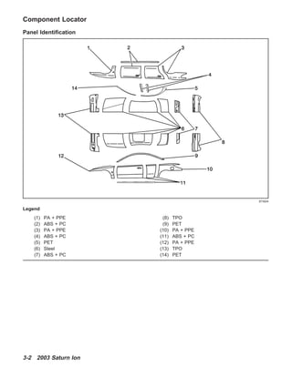
  • 1. Component Locator Panel Identification Legend (1) PA + PPE (2) ABS + PC (3) PA + PPE (4) ABS + PC (5) PET (6) Steel (7) ABS + PC (8) TPO (9) PET (10) PA + PPE (11) ABS + PC (12) PA + PPE (13) TPO (14) PET 873924 3-2 2003 Saturn Ion
  • 2. Exterior body panels are constructed of various materials, due to the increased dent and corrosion resistance of modern composites. All vertical panels, such as fenders, doors, quarters, and rocker panels, are made from rigid thermoplastic. Front and rear fascias are constructed of thermoplastic olefin (TPO). The hood, roof, and deck are steel. Different materials require different procedures for preparing and refinishing. Before beginning any repair, identify the type of material involved. Panel Identification Identifying Symbol Chemical Composition or Plastic “Family” Name Typical Area where Used Common or Trade Names PE Polyethylene Inner Fender Panels, Valances, Spoilers, Inner Trim Panels, Seatbelt Covers, Gas Tank Shields Dylan, Fortiflex, Marlex, Alathon, Hi-Fax, Hosalen, Paxon PP Polypropylene Kick Panels, Deflector Panels, Cowl Panels, Interior Moldings, Radiator Shrouds, Inner Fenders, Bumper Covers Profax, Oleflo, Marlex, Azdel, Novolen, Tenite, Daplen, Escorene ABS Acrylonitrite/Butadine/Styrene Instrument Clusters, Trim Moldings, Consoles, Armrest Supports, Steering Column Jackets ABS, Cycolac, Abson, Kralastic, Lustran, Absafil, Dyel ABS + PC Acrylonitrite/Butadine-Styrene + Polycarbonate Instrument Panels, Exterior Door Panels, Rocker Panel Covers Babyland, Proloy, Cycoloy, KHA E/P/TPO Ethylene/Polypropylene (Rubber) Bumper Covers TPO, TPR (Thermoplastic Rubber) EPI, EPII PA + PPE Polyamide + Polyphenylene Ether Fenders GTX 2003 Saturn Ion 3-3 2003SaturnIon
  • 3. Structure Identification Structure Identification Number Description Procedure 1 Impact Bar Bracket Replacement – Front Bumper Impact Bar Bracket Replacement - Front Bumper on page 3-15 2 Tie Bar Replacement Tie Bar Replacement on page 3-17 3 Tie Bar Replacement – Lower Tie Bar Replacement - Lower on page 3-21 4 Latch Primary Support Replacement – Hood Latch Primary Support Replacement - Hood on page 3-26 5 Tie Bar Replacement – Left Tie Bar Replacement - Left on page 3-19 6 Tie Bar Replacement – Right Tie Bar Replacement - Right on page 3-23 7 Bracket Replacement Side Rail – Front Compartment Bracket Replacement Front Compartment - Side Rail on page 3-30 867419 3-4 2003 Saturn Ion
  • 4. Structure Identification (cont’d) Number Description Procedure 8 Wheelhouse Replacement – Front Wheelhouse Replacement - Front on page 3-32 9 Wheelhouse Extension Replacement – Front Wheelhouse Extension Replacement - Front on page 3-34 10 Rail Replacement Front Compartment – Side Upper Rail Replacement Front Compartment - Side Upper on page 3-36 11 Rail Sectioning Front Compartment – Side Upper Rail Sectioning Front Compartment - Side Upper on page 3-39 12 Plenum Panel Replacement – Upper Plenum Panel Replacement - Upper on page 3-43 13 Plenum Panel Replacement – Lower Plenum Panel Replacement - Lower on page 3-45 14 Dash Panel Replacement Dash Panel Replacement on page 3-48 15 Cross Bar New Replacement – Floor Panel Cross Bar No.1 Replacement - Floor Panel on page 3-51 16 Rail Replacement Front Compartment – Front Rail Replacement Front Compartment - Front on page 3-53 17 Rail Replacement Front Compartment – Front Half Rail Replacement Front Compartment - Front Half on page 3-55 18 Rail Sectioning Front Compartment – Front Rail Sectioning Front Compartment - Front on page 3-59 19 Rail Replacement Front Side Underbody – Outer Rail Replacement Front Side Underbody - Outer on page 3-63 20 Suspension Support Replacement – Front Suspension Support Replacement - Front on page 3-66 21 Extension Replacement Front Compartment Side Rail – Rear Extension Replacement Front Compartment Side Rail - Rear on page 3-68 22 Windshield Frame Reinforcement Replacement – Inner Upper Windshield Frame Reinforcement Replacement - Inner Upper on page 3-70 23 Hinge Pillar Body Replacement – Front Inner Hinge Pillar Body Replacement - Front Inner on page 3-75 24 Hinge Pillar Body Reinforcement Replacement – Front Inner Hinge Pillar Body Reinforcement Replacement - Front Inner on page 3-73 25 Hinge Pillar Body Sectioning – Front Hinge Pillar Body Sectioning - Front on page 3-78 26 Roof Panel Replacement – Outer Roof Panel Replacement - Outer on page 3-81 27 Windshield Frame Header Panel Replacement – Front Windshield Frame Header Panel Replacement - Front on page 3-85 28 Rear Window Frame Header Panel Replacement – Rear Rear Window Frame Header Panel Replacement - Rear on page 3-87 29 Floor Panel Replacement – Center Floor Panel Replacement - Center on page 3-89 30 Rocker Panel Replacement – Inner Rocker Panel Replacement - Inner on page 3-93 31 Rocker Panel Extension Replacement – Inner Rocker Panel Extension Replacement - Inner on page 3-95 32 Rocker Panel Reinforcement Replacement – Inner Rocker Panel Reinforcement Replacement - Inner on page 3-97 33 Rocker Panel Reinforcement Sectioning – Inner Rocker Panel Reinforcement Sectioning - Inner on page 3-100 2003 Saturn Ion 3-5 2003SaturnIon
  • 5. Structure Identification (cont’d) Number Description Procedure 34 Pillar Lock Front Door Sectioning – Outer Pillar Lock Front Door Sectioning - Outer on page 3-103 35 Pillar Lock Front Door Reinforcement Replacement – Outer Pillar Lock Front Door Reinforcement Replacement - Outer on page 3-107 36 Pillar Lock Front Door Reinforcement Pillar Lock Front Door Reinforcement Sectioning - Outer on page 3-109 37 Pillar Lock Front Door Replacement – Inner Pillar Lock Front Door Replacement - Inner on page 3-112 38 Pillar Lock Front Door Sectioning Replacement – Outer Pillar Lock Front Door Reinforcement Sectioning - Outer on page 3-109 39 Rear Window Reinforcement Replacement – Lower Front Rear Window Reinforcement Replacement - Lower Front on page 3-114 40 Rear Window Panel Replacement Rear Window Panel Replacement on page 3-116 41 Rear Window Reinforcement – Rear Rear Window Reinforcement Replacement - Rear on page 3-119 42 Pillar Lock Rear Door Replacement – Inner Pillar Lock Rear Door Replacement - Inner on page 3-121 43 Body Side Panel Replacement – Outer Body Side Panel Replacement - Outer on page 3-123 44 Rear Compartment Floor Panel Sectioning Rear Compartment Floor Panel Sectioning on page 3-126 45 Wheelhouse Replacement – Rear Inner Wheelhouse Replacement - Rear Inner on page 3-130 46 Quarter Panel Sectioning – Outer Quarter Panel Sectioning - Outer on page 3-133 47 Quarter Panel Replacement – Inner Quarter Panel Replacement - Inner on page 3-136 48 Cross Bar No. 4 Replacement – Floor Panel Cross Bar No.4 Replacement - Floor Panel on page 3-140 49 Cross Bar No. 4 Extension Replacement – Floor Panel Cross Bar No.4 Extension Replacement - Floor Panel on page 3-138 50 Cross Bar No. 5 Replacement – Floor Panel Center Cross Bar No.5 Replacement - Floor Panel on page 3-145 51 Cross Bar No. 5 Extension Replacement – Floor Panel Cross Bar No.5 Extension Replacement - Floor Panel on page 3-143 52 Rail Replacement Rear Side Underbody Rail Replacement Rear Side Underbody on page 3-147 53 Rail Sectioning Rear Side Underbody Rail Sectioning Rear Side Underbody on page 3-150 54 Rail Side Underbody Gusset Replacement – Rear Rail Underbody Gusset Replacement - Rear on page 3-155 55 Rail Side Underbody Reinforcement Replacement – Rear Rail Underbody Reinforcement Replacement - Rear on page 3-157 56 Impact Bar Anchor Plate Replacement – Rear Bumper Impact Bar Anchor Plate Replacement - Rear Bumper on page 3-160 57 Body Rear End Panel Replacement Body Rear End Panel Replacement on page 3-162 58 Battery Tray Replacement Battery Tray Replacement on page 3-28 3-6 2003 Saturn Ion
  • 6. Specifications Dimensions - Body Rear End Location Description Length = x Width = y Height = z Point to Point 2 Center Line — — — x a Rear Tail Lamp Pocket Hole 5162 532 683 x b Rear Impact Beam Upper Outer Attach Hole 5149 587 447 x c Rear Impact Beam Lower Outer Attach Hole 5176 439 327 x d (Sedan) Rear Header Panel Roof Attachment Hole 4133 306 1326 x d (Coupe) Rear Header Panel Roof Attachment Hole 4068 306 1285 x All dimensions are measured from a zero line, a center line, and a common datum. All dimensions are symmetrical unless otherwise specified. 876934 2003 Saturn Ion 3-7 2003SaturnIon
  • 7. Coupe Side Location Description Length = x Width = y Height = z Point to Point a Rear Lower Hinge Lower Hole 3996 770 555 x b Rear Lower Hinge Upper Hole 4046 759 649 x c Rear Upper Hinge Lower Hole 4067 747 758 x d Rear Upper Hinge Upper Hole 4056 738 863 x e Fascia Bracket Rear Upper Hole 4989 768 798 x f Quarter Panel Rear Inner Lower Hole 4822 730 445 x g Quarter Panel Dog Leg Outer Attach Hole 3955 762 320 x h Quarter Panel Dog Leg Outer Attach Hole 3961 762 235 x i Rocker Panel Rear Hole 3780 762 250 x j Rocker Panel Center Hole 3228 756 234 x k Rocker Panel Front Hole 2432 762 250 x l Front Lower Hinge Rear Hole 2260 750 396 x m Front Lower Hinge Front Hole 2225 750 396 x n Body Side Control Hole 2175 745 640 x o Front Upper Hinge Front Hole 2225 739 754 x p Front Upper Hinge Rear Hole 2260 739 754 x 876935 3-8 2003 Saturn Ion
  • 8. Location Description Length = x Width = y Height = z Point to Point q Door Opening Point to Point Measurement to Weld Flange Die Marks x x x 1588 r Door Opening Point to Point Measurement to Weld Flange Die Marks x x x 1868 All dimensions are measured from a zero line, a center line, and a common datum. All dimensions are symmetrical unless otherwise specified. Front End Location Description Length = x Width = y Height = z Point to Point 2 Center Line — — — x a Front Lamp Assembly Inner Attach Hole 1146 327 675 x b Front Lamp Assembly Center Attach Hole 1208 458 682 x c Front Lamp Assembly Outer Attach Hole 1271 589 676 x d Front Lamp Assembly Lower Attach Hole 1307 561 594 x e Lower Tie Bar Outer Hole 998 314 428 x f Center Brace Hole 1089 17 568 x g Lower Tie Outer Slot 998 314 428 x h Front Header Panel Roof Attachment Hole (Sedan and Coupe) 2799 297 1307 x All dimensions are measured from a zero line, a center line, and a common datum. All dimensions are symmetrical unless otherwise specified. 876936 2003 Saturn Ion 3-9 2003SaturnIon
  • 10. Location Description Length = x Width = y Height = z Point to Point 2 Center Line — — — x a Rear Cradle Attachment Hole 2100 332 201 x b Front Rail Outer Torque Box Master Gage Hole 2218 600 121 x c Floor Pan Drain Hole Front Hole 2420 542 190 x d Front Rail Hole Front of Rear Portion 2675 421 134 x e Floor Pan Sled Rail Front Hole 2585 162 133 x f Front Rail Hole Rear of Rear Portion 3171 601 167 x g Floor Pan Sled Rail Rear Hole 3374 170 144 x h Floor Pan Rear Drain Hole 3378 521 190 x i Rear Rail Torque Box Master Gage Hole 3593 592 203 x j Front Rail Hole 3826 600 184 x k 5 Bar Outer Hole 4235 180 354 x l Rear Rail Rear Slot 4757 487 372 x m Rear Compartment Floor Pan Drain Hole 5000 40 221 x t Front Cradle Attachment Hole 1371 474 231 x n to o Rear Rail Rear Hole to Rear Rail Master Gage Hole — — — 1174 o to p Rear Rail Master Gage Hole to Front Rail Rear Hole — — — 419 p to q Front Rail Rear Hole to Front Rail Master Gage Hole — — — 956 q to s Front Rail Master Gage Hole to Front Cradle Attachment Hole — — — 847 r to s Rear Cradle Attachment Hole to Front Cradle Attachment Hole — — — 742 s to t Front Cradle Attachment Hole to Front Cradle Attachment Hole — — — 948 t to r Front Cradle Attachment Hole to Opposite Rear Cradle Attachment — — — 1087 r to f Rear Cradle Attachment Hole to Opposite Rear Rail Rear Hole — — — 1756 r to i Rear Cradle Attachment Hole to Rear Rail Master Gage Hole — — — 1756 f to o Front Rail Rear Hole to Opposite Rear Rail Master Gage Hole — — — 1243 o to l Rear Rail Master Gage Hole to Opposite Rear Rail Rear Hole — — — 1591 l to n Rear Rail Rear Hole to Rear Rail Rear Hole — — — 974 All dimensions are measured from a zero line, a center line, and a common datum. All dimensions are symmetrical unless otherwise specified. 2003 Saturn Ion 3-11 2003SaturnIon
  • 11. Engine Compartment Location Description Length = x Width = y Height = z Point to Point 2 Center Line — — — x a Upper Cowl Panel Rear Flange Hole 2115 590 873 x b Front Upper Rail Rear Fender Attach 1786 698 805 x c Front Upper Rail Center Fender Attach 1594 688 773 x d Front Upper Rail Front Fender Attach 1425 681 739 x e Strut Tower Center Hole 1811 553 815 x f Front Upper Tie Bar Rear Flange Hole 1226 232 700 x g Point to Point Front Fender Attach Hole to Rear Hinge Attach Hole — — — 1499 h Front Engine Mount Hole Rail Surface Not Top of Stud 1461 470 515 x i Rear Engine Mount Hole Rail Surface Not Top of Stud 1657 465 515 x All dimensions are measured from a zero line, a center line, and a common datum. All dimensions are symmetrical unless otherwise specified. 876940 3-12 2003 Saturn Ion
  • 12. Sedan Side 876943 2003 Saturn Ion 3-13 2003SaturnIon
  • 13. Location Description Length = x Width = y Height = z Point to Point a Rear Upper Hinge Upper Hole 3301 746 776 x b Quarter Panel Dog Leg Outer Attachment Hole 4226 779 768 x c Fascia Bracket Rear Upper Hole 4974 746 596 x d Quarter Panel Dog Leg Outer Attach Hole 4068 767 617 x e Quarter Panel Dog Leg Outer Attachment Hole 3991 767 437 x f Quarter Panel Dog Leg Outer Attachment Hole 3780 762 250 x g Rear Lower Hinge Rear Hole 3289 746 430 x h Rear Lower Hinge Front Hole 3254 747 430 x i Front Lower Hinge Rear Hole 2259 748 396 x j Rear Cradle Attachment Hole 2100 332 201 x k Front Lower Hinge Front Hole 2225 740 396 x l Front Rail Outer Panel Hole 1840 463 430 x m Front Cradle Attachment Hole 1371 500 280 x n Weld Nut Hole Washer Bottle Attachment 1222 540 409 x o Front Upper Outer Rail Front Hole 1880 743 760 x p Body Side Control Hole 2175 745 640 x q Front Upper Hinge Front Hole 2224 737 754 x r Front Upper Hinge Rear Hole 2260 737 754 x s Front Door Latch Striker Upper Hole 3263 748 574 x t Rear Upper Hinge Lower Hole 3299 754 741 x u Rear Latch Striker Upper Hole 4145 739 736 x v Rear Door Opening Point to Point Measurements to Weld Flange Die Marks — — — 1015 w Rear Door Opening Point to Point Measurement to Weld Flange Die Marks — — — 1188 x Front Door Opening Point to Point Measurement to Weld Flange Die Marks — — — 970 y Front Door Opening Point to Point Measurement to Weld Flange Die Marks — — — 1337 All dimensions are measured from a zero line, a center line, and a common datum. All dimensions are symmetrical unless otherwise specified. 3-14 2003 Saturn Ion
  • 14. Repair Instructions Impact Bar Bracket Replacement - Front Bumper Removal Procedure Caution: To avoid personal injury when exposed to welding flashes or to galvanized (Zinc Oxide) metal toxic fumes while grinding/cutting on any type of metal or sheet molded compound, you must work in a properly ventilated area, wearing an approved respirator, eye protection, earplugs, welding gloves, and protective clothing. 1. Disable the SIR system. 2. Disconnect the negative battery cable. 3. Remove all related panels and components. 4. Repair as much of the damage as possible. Refer to Dimensions - Body on page 3-7. 5. Remove the sealers and anti-corrosion materials from the repair area, as necessary. Important: Note the number and location of the factory welds for installation of the impact bar bracket - front bumper 6. Locate and drill out all the factory welds from the outside surface of the rail. 868868 867608 2003 Saturn Ion 3-15 2003SaturnIon
  • 15. 7. Remove the front bumper impact bar bracket. Installation Procedure 1. Prepare all mating surfaces as necessary. 2. Apply 3M Weld-Thru Coating P/N 05916 or equivalent to all mating surfaces. Important: Verify the location of the front rail using 3-dimensional measuring equipment. 3. Position the impact bar bracket on the rail and clamp in place. 867609 867597 867609 3-16 2003 Saturn Ion
  • 16. 4. Plug weld accordingly. 5. Clean and prepare all of the welded surfaces. 6. Install all of the related panels and components. 7. Apply the sealers and anti-corrosion materials to the repair area, as necessary. 8. Paint the repaired area. 9. Connect the negative battery cable. 10. Enable the SIR system. Tie Bar Replacement Removal Procedure Caution: To avoid personal injury when exposed to welding flashes or to galvanized (Zinc Oxide) metal toxic fumes while grinding/cutting on any type of metal or sheet molded compound, you must work in a properly ventilated area, wearing an approved respirator, eye protection, earplugs, welding gloves, and protective clothing. 1. Disable the SIR system. 2. Disconnect the negative battery cable. 3. Remove all related panels and components. 4. Repair as much of the damage as possible to factory specifications. Refer to Dimensions - Body on page 3-7. 5. Note the location and remove the sealers and anti-corrosion materials from the repair area, as necessary. Important: Do not damage any inner panels or reinforcements. 6. Locate and drill out all factory welds. Note the number and location of the welds for installation of the tie bar. 868868 867423 867488 2003 Saturn Ion 3-17 2003SaturnIon
  • 17. 7. Remove the damaged tie bar. Installation Procedure Important: If the location of the original plug weld holes can not be determined, space the plug weld holes every 40 mm (1 1/2 in) apart. 1. Drill 8 mm (5/16 in) plug weld holes in the service part as necessary in the locations noted from the original panel. 2. Prepare all mating surfaces as necessary. 3. Apply 3M Weld-Thru Coating P/N 05916 or equivalent to all mating surfaces. 4. Position the tie bar to the vehicle using 3-dimensional measuring equipment. Clamp the tie bar into place. 5. Plug weld accordingly. 6. Clean and prepare all welded surfaces. 7. Apply the sealers and anti-corrosion materials to the repair area, as necessary. 8. Paint the repair area. 9. Install all related panels and components. 10. Connect the negative battery cable. 11. Enable the SIR system. 867491 865271 867423 3-18 2003 Saturn Ion
  • 18. Tie Bar Replacement - Left Removal Procedure Caution: To avoid personal injury when exposed to welding flashes or to galvanized (Zinc Oxide) metal toxic fumes while grinding/cutting on any type of metal or sheet molded compound, you must work in a properly ventilated area, wearing an approved respirator, eye protection, earplugs, welding gloves, and protective clothing. Caution: When performing service on or near the SIR components or the SIR wiring, the SIR system must be disabled. Refer to SIR Disabling and Enabling Zones. Failure to observe the correct procedure could cause deployment of the SIR components, personal injury, or unnecessary SIR system repairs. 1. Disable the SIR system. Caution: Before servicing any electrical component, the ignition key must be in the OFF or LOCK position and all electrical loads must be OFF, unless instructed otherwise in these procedures. If a tool or equipment could easily come in contact with a live exposed electrical terminal, also disconnect the negative battery cable. Failure to follow these precautions may cause personal injury and/or damage to the vehicle or its components. 2. Disconnect the negative battery cable. 3. Remove all related panels and components. 4. Repair as much of the damage as possible. Refer to Dimensions - Body on page 3-7. 5. Remove the sealers and anti-corrosion materials from the repair area, as necessary. Important: Note the number and location of the factory welds for installation of the tie bar-left. 6. Locate and drill out all the necessary factory welds. 867423 867500 2003 Saturn Ion 3-19 2003SaturnIon
  • 19. 7. Remove the left tie bar. Installation Procedure Important: If the location of the original plug weld holes can not be determined, space the plug weld holes every 40 mm (1 1/2 in) apart. 1. Drill 8 mm (5/16 in) plug weld holes in the service part as necessary in the locations noted from the original panel. 2. Prepare all mating surfaces as necessary. 3. Apply 3M Weld-Thru Coating P/N 05916 or equivalent to all mating surfaces. 4. Position the left tie bar to the vehicle using 3-dimensional measuring equipment. Clamp the tie bar in place. 867504 865272 867504 3-20 2003 Saturn Ion
  • 20. 5. Plug weld accordingly. 6. Clean and prepare all of the welded surfaces. 7. Install all of the related panels and components. 8. Apply the sealers and anti-corrosion materials to the repair area, as necessary. 9. Paint the repaired area. 10. Connect the negative battery cable. 11. Enable the SIR system. Tie Bar Replacement - Lower Removal Procedure Caution: To avoid personal injury when exposed to welding flashes or to galvanized (Zinc Oxide) metal toxic fumes while grinding/cutting on any type of metal or sheet molded compound, you must work in a properly ventilated area, wearing an approved respirator, eye protection, earplugs, welding gloves, and protective clothing. Caution: When performing service on or near the SIR components or the SIR wiring, the SIR system must be disabled. Refer to SIR Disabling and Enabling Zones. Failure to observe the correct procedure could cause deployment of the SIR components, personal injury, or unnecessary SIR system repairs. 1. Disable the SIR system. Caution: Before servicing any electrical component, the ignition key must be in the OFF or LOCK position and all electrical loads must be OFF, unless instructed otherwise in these procedures. If a tool or equipment could easily come in contact with a live exposed electrical terminal, also disconnect the negative battery cable. Failure to follow these precautions may cause personal injury and/or damage to the vehicle or its components. 2. Disconnect the negative battery cable. Important: This panel is replaced at factory seams or can be unbolted for removal. 3. Remove all related panels and components. 4. Repair as much of the damage as possible. Refer to Dimensions - Body on page 3-7. 5. Remove the sealers and anti-corrosion materials from the repair area, as necessary. 867423 867423 2003 Saturn Ion 3-21 2003SaturnIon
  • 21. Important: Note the number and location of the factory welds for installation of the lower tie bar. 6. Locate and drill out all the necessary factory welds. 7. Remove the lower tie bar. Installation Procedure Important: If the location of the original plug weld holes can not be determined, space the plug weld holes every 40 mm (1 1/2 in) apart. 1. Drill 8 mm (5/16 in) plug weld holes in the service part as necessary in the locations noted from the original panel. 2. Prepare all mating surfaces as necessary. 3. Apply 3M Weld-Thru Coating P/N 05916 or equivalent to all mating surfaces. 867424 867470 865257 3-22 2003 Saturn Ion
  • 22. 4. Position the tie bar on the vehicle using 3-dimensionial measuring equipment. Clamp the tie bar into place. 5. Plug weld accordingly. 6. Clean and prepare all of the welded surfaces. 7. Install all of the related panels and components. 8. Apply the sealers and anti-corrosion materials to the repair area, as necessary. 9. Paint the repaired area. 10. Connect the negative battery cable. 11. Enable the SIR system. Tie Bar Replacement - Right Removal Procedure Caution: To avoid personal injury when exposed to welding flashes or to galvanized (Zinc Oxide) metal toxic fumes while grinding/cutting on any type of metal or sheet molded compound, you must work in a properly ventilated area, wearing an approved respirator, eye protection, earplugs, welding gloves, and protective clothing. Caution: Refer to SIR Caution on page 1-1 in General Information. Important: The graphic shows the left hand procedure. The right hand procedure is similar. 1. Disable the SIR system. 867470 867423 867423 2003 Saturn Ion 3-23 2003SaturnIon
  • 23. Caution: Before servicing any electrical component, the ignition key must be in the OFF or LOCK position and all electrical loads must be OFF, unless instructed otherwise in these procedures. If a tool or equipment could easily come in contact with a live exposed electrical terminal, also disconnect the negative battery cable. Failure to follow these precautions may cause personal injury and/or damage to the vehicle or its components. 2. Disconnect the negative battery cable. 3. Remove all related panels and components. 4. Repair as much of the damage as possible. Refer to Dimensions - Body on page 3-7. 5. Remove the sealers and anti-corrosion materials from the repair area, as necessary. Important: Note the number and location of the factory welds for installation of the right tie bar. 6. Locate and drill out all the necessary factory welds. 7. Remove the right tie bar panel from the vehicle. 867500 867504 3-24 2003 Saturn Ion
  • 24. Installation Procedure Important: If the location of the original plug weld holes can not be determined, space the plug weld holes every 40 mm (1 1/2 in) apart. 1. Drill 8 mm (5/16 in) plug weld holes in the service part as necessary in the locations noted from the original panel. 2. Prepare all mating surfaces as necessary. 3. Apply 3M Weld-Thru Coating P/N 05916 or equivalent to all mating surfaces. 4. Position the right tie bar panel to the vehicle using 3-dimensional measuring equipment. Clamp the tie bar in place. 5. Plug weld accordingly. 6. Clean and prepare all of the welded surfaces. 7. Install all of the related panels and components. 8. Apply the sealers and anti-corrosion materials to the repair area, as necessary. 9. Paint the repaired area. 10. Connect the negative battery cable. 11. Enable the SIR system. 865272 867504 867423 2003 Saturn Ion 3-25 2003SaturnIon
  • 25. Latch Primary Support Replacement - Hood Removal Procedure Caution: To avoid personal injury when exposed to welding flashes or to galvanized (Zinc Oxide) metal toxic fumes while grinding/cutting on any type of metal or sheet molded compound, you must work in a properly ventilated area, wearing an approved respirator, eye protection, earplugs, welding gloves, and protective clothing. Caution: When performing service on or near the SIR components or the SIR wiring, the SIR system must be disabled. Refer to SIR Disabling and Enabling Zones. Failure to observe the correct procedure could cause deployment of the SIR components, personal injury, or unnecessary SIR system repairs. 1. Disable the SIR system. Caution: Before servicing any electrical component, the ignition key must be in the OFF or LOCK position and all electrical loads must be OFF, unless instructed otherwise in these procedures. If a tool or equipment could easily come in contact with a live exposed electrical terminal, also disconnect the negative battery cable. Failure to follow these precautions may cause personal injury and/or damage to the vehicle or its components. 2. Disconnect the negative battery cable. 3. Remove all related panels and components. 4. Repair as much of the damage as possible. Refer to Dimensions - Body on page 3-7. 5. Remove the sealers and anti-corrosion materials from the repair area, as necessary. Important: Note the number and location of the factory welds for installation of the latch primary support. 6. Locate and drill out all the necessary factory welds. 867423 867511 3-26 2003 Saturn Ion
  • 26. 7. Remove the latch primary support. Installation Procedure Important: If the location of the original plug weld holes can not be determined, space the plug weld holes every 40 mm (1 1/2 in) apart. 1. Drill 8 mm (5/16 in) plug weld holes in the service part as necessary in the locations noted from the original panel. 2. Prepare all mating surfaces as necessary. 3. Apply 3M Weld-Thru Coating P/N 05916 or equivalent to all mating surfaces. 4. Position the latch primary support on the vehicle using 3-dimensional measuring equipment. Clamp the support into place. 867514 865273 867514 2003 Saturn Ion 3-27 2003SaturnIon
  • 27. 5. Plug weld accordingly. 6. Clean and prepare all of the welded surfaces. 7. Install all of the related panels and components. 8. Apply the sealers and anti-corrosion materials to the repair area, as necessary. 9. Paint the repaired area. 10. Connect the negative battery cable. 11. Enable the SIR system. Battery Tray Replacement Removal Procedure Caution: To avoid personal injury when exposed to welding flashes or to galvanized (Zinc Oxide) metal toxic fumes while grinding/cutting on any type of metal or sheet molded compound, you must work in a properly ventilated area, wearing an approved respirator, eye protection, earplugs, welding gloves, and protective clothing. Caution: When performing service on or near the SIR components or the SIR wiring, the SIR system must be disabled. Refer to SIR Disabling and Enabling Zones. Failure to observe the correct procedure could cause deployment of the SIR components, personal injury, or unnecessary SIR system repairs. 1. Disable the SIR system. Caution: Before servicing any electrical component, the ignition key must be in the OFF or LOCK position and all electrical loads must be OFF, unless instructed otherwise in these procedures. If a tool or equipment could easily come in contact with a live exposed electrical terminal, also disconnect the negative battery cable. Failure to follow these precautions may cause personal injury and/or damage to the vehicle or its components. 2. Disconnect the negative battery cable. Important: This panel is replaced at factory seams. 3. Remove all related panels and components. 4. Repair as much of the damaged area as possible. Refer to Dimensions - Body on page 3-7. 5. Remove the sealers and anti-corrosion materials from the repair area, as necessary. 867423 872730 3-28 2003 Saturn Ion
  • 28. Important: Note the number and location of the factory welds for installation of the battery tray. 6. Locate and drill out all the necessary factory welds. 7. Remove the battery tray. Installation Procedure Important: If the location of the original plug weld holes can not be determined, space the plug weld holes every 40 mm (1 1/2 in) apart. 1. Drill 8 mm (5/16 in) plug weld holes in the service part as necessary in the locations noted from the original panel. 2. Prepare all mating surfaces for welding as necessary. 3. Apply 3M Weld-Thru Coating P/N 05916 or equivalent to all mating surfaces. 4. Position the battery tray to the vehicle. Clamp the battery tray in place. 5. Plug weld accordingly. 6. Clean and prepare all of the welded surfaces. 7. Install all of the related panels and components. 8. Apply the sealers and anti-corrosion materials to the repair area, as necessary. 9. Paint the repaired area. 10. Connect the negative battery cable. 11. Enable the SIR system. 872732 872732 872730 2003 Saturn Ion 3-29 2003SaturnIon
  • 29. Bracket Replacement Front Compartment - Side Rail Removal Procedure Caution: To avoid personal injury when exposed to welding flashes or to galvanized (Zinc Oxide) metal toxic fumes while grinding/cutting on any type of metal or sheet molded compound, you must work in a properly ventilated area, wearing an approved respirator, eye protection, earplugs, welding gloves, and protective clothing. Caution: When performing service on or near the SIR components or the SIR wiring, the SIR system must be disabled. Refer to SIR Disabling and Enabling Zones. Failure to observe the correct procedure could cause deployment of the SIR components, personal injury, or unnecessary SIR system repairs. 1. Disable the SIR system. Caution: Before servicing any electrical component, the ignition key must be in the OFF or LOCK position and all electrical loads must be OFF, unless instructed otherwise in these procedures. If a tool or equipment could easily come in contact with a live exposed electrical terminal, also disconnect the negative battery cable. Failure to follow these precautions may cause personal injury and/or damage to the vehicle or its components. 2. Disconnect the negative battery cable. 3. Remove all related panels and components. 4. Repair as much of the damage as possible. Refer to Dimensions - Body on page 3-7. 5. Remove the sealers and anti-corrosion materials from the repair area, as necessary. Important: Note the number and location of the factory welds for installation of the bracket side rail-front compartment. 6. Locate and drill out all the necessary factory welds. 867612 867617 3-30 2003 Saturn Ion
  • 30. 7. Remove the side rail bracket from the front compartment lower rail. Installation Procedure Important: If the location of the original plug weld holes can not be determined, space the plug weld holes every 40 mm (1 1/2 in) apart. 1. Drill 8 mm (5/16 in) plug weld holes in the service part as necessary in the locations noted from the original panel. 2. Prepare all mating surfaces as necessary. 3. Apply 3M Weld-Thru Coating P/N 05916 or equivalent to all mating surfaces. 4. Position the side rail bracket to the front compartment lower rail and tie bar side panel. Clamp the bracket in place. 867618 865267 867618 2003 Saturn Ion 3-31 2003SaturnIon
  • 31. 5. Plug weld accordingly. 6. Clean and prepare all of the welded surfaces. 7. Install all of the related panels and components. 8. Apply the sealers and anti-corrosion materials to the repair area, as necessary. 9. Paint the repaired area. 10. Connect the negative battery cable. 11. Enable the SIR system. Wheelhouse Replacement - Front Removal Procedure Caution: To avoid personal injury when exposed to welding flashes or to galvanized (Zinc Oxide) metal toxic fumes while grinding/cutting on any type of metal or sheet molded compound, you must work in a properly ventilated area, wearing an approved respirator, eye protection, earplugs, welding gloves, and protective clothing. Caution: When performing service on or near the SIR components or the SIR wiring, the SIR system must be disabled. Refer to SIR Disabling and Enabling Zones. Failure to observe the correct procedure could cause deployment of the SIR components, personal injury, or unnecessary SIR system repairs. 1. Disable the SIR system. 2. Disconnect the negative battery cable. Important: The upper strut mounting surface is a dimensionally critical area, and 3-dimensional measuring equipment should be used to locate the front wheelhouse assembly. The front wheelhouse can be serviced as a complete assembly for both the left and right wheelhouses. A wheelhouse front panel is also available to service separately on the left or the right sides. 3. Remove the sealers and anti-corrosion materials from the repair area, as necessary. Important: Be sure to inspect the front of the cowl and dash panel for damage. If the metal surface is damaged, the cowl panel must be repaired to restore the structural integrity of the vehicle. 4. Visually inspect the damaged area. Repair as much of the damage as possible. Refer to Dimensions - Body on page 3-7. 867612 867478 3-32 2003 Saturn Ion
  • 32. 5. Locate and drill out all factory welds. Important: Note the number and location of welds for installation of the front wheelhouse. 6. Remove the front wheelhouse from the vehicle. Installation Procedure Important: If the location of the original plug weld holes can not be determined, space the plug weld holes every 40 mm (1 1/2 in) apart. 1. Drill 8 mm (5/16 in) plug weld holes as necessary in the locations noted from the original assembly. 2. Prepare the mating surfaces as necessary. 3. Apply 3M Weld-Thru Coating P/N 05916 or equivalent to all mating surfaces. 4. Position the front wheelhouse in the vehicle using 3-dimensional measuring equipment. Clamp the wheelhouse in place. 867495 867507 865277 2003 Saturn Ion 3-33 2003SaturnIon
  • 33. 5. Plug weld accordingly. 6. Clean and prepare all of the welded surfaces. 7. Install all related panels and components. 8. Apply the sealers and anti-corrosion materials to the repair area, as necessary. 9. Paint the repaired area. 10. Connect the negative battery cable. 11. Enable the SIR system. Wheelhouse Extension Replacement - Front Removal Procedure Caution: To avoid personal injury when exposed to welding flashes or to galvanized (Zinc Oxide) metal toxic fumes while grinding/cutting on any type of metal or sheet molded compound, you must work in a properly ventilated area, wearing an approved respirator, eye protection, earplugs, welding gloves, and protective clothing. Caution: When performing service on or near the SIR components or the SIR wiring, the SIR system must be disabled. Refer to SIR Disabling and Enabling Zones. Failure to observe the correct procedure could cause deployment of the SIR components, personal injury, or unnecessary SIR system repairs. 1. Disable the SIR system. Caution: Before servicing any electrical component, the ignition key must be in the OFF or LOCK position and all electrical loads must be OFF, unless instructed otherwise in these procedures. If a tool or equipment could easily come in contact with a live exposed electrical terminal, also disconnect the negative battery cable. Failure to follow these precautions may cause personal injury and/or damage to the vehicle or its components. 2. Disconnect the negative battery cable. 3. Remove all related panels and components. 4. Repair as much of the damage as possible. Refer to Dimensions - Body on page 3-7. 5. Remove the sealers and anti-corrosion materials from the repair area, as necessary. 867495 868716 3-34 2003 Saturn Ion
  • 34. Important: Note the number and location of the factory welds for installation of the front wheelhouse extension. 6. Locate and drill out all the necessary factory welds. 7. Remove the front wheelhouse extension. Installation Procedure Important: If the location of the original plug weld holes can not be determined, space the plug weld holes every 40 mm (1 1/2 in) apart. 1. Drill 8 mm (5/16 in) plug weld holes in the service part as necessary in the locations noted from the original panel. 2. Prepare all mating surfaces as necessary. 3. Apply 3M Weld-Thru Coating P/N 05916 or equivalent to all mating surfaces. 868717 868718 865281 2003 Saturn Ion 3-35 2003SaturnIon
  • 35. 4. Position the front wheelhouse extension to the vehicle using 3-dimensional measuring equipment. Clamp the extension in place. 5. Plug weld accordingly. 6. Clean and prepare all of the welded surfaces. 7. Install all of the related panels and components. 8. Apply the sealers and anti-corrosion materials to the repair area, as necessary. 9. Paint the repaired area. 10. Connect the negative battery cable. 11. Enable the SIR system. Rail Replacement Front Compartment - Side Upper Removal Procedure Caution: To avoid personal injury when exposed to welding flashes or to galvanized (Zinc Oxide) metal toxic fumes while grinding/cutting on any type of metal or sheet molded compound, you must work in a properly ventilated area, wearing an approved respirator, eye protection, earplugs, welding gloves, and protective clothing. Caution: Refer to SIR Caution on page 1-1 in General Information. 1. Disable the SIR system. 868718 868716 868719 3-36 2003 Saturn Ion
  • 36. Caution: Before servicing any electrical component, the ignition key must be in the OFF or LOCK position and all electrical loads must be OFF, unless instructed otherwise in these procedures. If a tool or equipment could easily come in contact with a live exposed electrical terminal, also disconnect the negative battery cable. Failure to follow these precautions may cause personal injury and/or damage to the vehicle or its components. 2. Disconnect the negative battery cable. 3. Remove all related panels and components. 4. Repair as much of the damage as possible to factory specifications. Refer to Dimensions - Body on page 3-7. 5. Remove the sealers and anti-corrosion materials from the repair area, as necessary. Important: Do not damage any inner panels or reinforcements. 6. Locate and drill out all factory welds. Note the number and location of the welds for installation of the front upper rail. 7. Remove the damaged front upper rail. 868721 868722 2003 Saturn Ion 3-37 2003SaturnIon
  • 37. Installation Procedure Important: If the location of the original plug weld holes can not be determined, space the plug weld holes every 40 mm (1 1/2 in) apart. 1. Drill 8 mm (5/16 in) plug weld holes in the service part as necessary in the locations noted from the original panel. 2. Prepare all mating surfaces as necessary. 3. Apply 3M Weld-Thru Coating P/N 05916 or equivalent to all mating surfaces. 4. Position the front upper rail on the vehicle using 3-dimensional measuring equipment. Clamp the rail in place. 5. Plug weld accordingly. 6. Clean and prepare all welded surfaces. 7. Install all related panels and components. 8. Apply the sealers and anti-corrosion materials to the repair area, as necessary. 9. Paint the repair area. 10. Connect the negative battery cable. 11. Enable the SIR system. 868720 868722 868719 3-38 2003 Saturn Ion
  • 38. Rail Sectioning Front Compartment - Side Upper Removal Procedure Caution: To avoid personal injury when exposed to welding flashes or to galvanized (Zinc Oxide) metal toxic fumes while grinding/cutting on any type of metal or sheet molded compound, you must work in a properly ventilated area, wearing an approved respirator, eye protection, earplugs, welding gloves, and protective clothing. Caution: Sectioning should be performed only in the recommended areas. Failure to do so may compromise the structural integrity of the vehicle and cause personal injury if the vehicle is in a collision. Caution: Refer to SIR Caution on page 1-1 in General Information. 1. Disable the SIR system. Caution: Before servicing any electrical component, the ignition key must be in the OFF or LOCK position and all electrical loads must be OFF, unless instructed otherwise in these procedures. If a tool or equipment could easily come in contact with a live exposed electrical terminal, also disconnect the negative battery cable. Failure to follow these precautions may cause personal injury and/or damage to the vehicle or its components. 2. Disconnect the negative battery cable. 3. Remove all related panels and components. 4. Repair as much of the damage as possible. Refer to Dimensions - Body on page 3-7. 5. Remove the sealers and anti-corrosion materials from the repair area, as necessary. Important: Note the number and location of the factory welds for installation of the front compartment of the side upper rail. 6. Locate and drill out all the necessary factory welds. 868719 874293 2003 Saturn Ion 3-39 2003SaturnIon
  • 39. 7. Measure forward 50 mm (2 in) (a) of the center of the third fender bolt hole location. Mark the location. 8. Using the mark made in the previous step as a starting point, use a sliding square to transfer a line on the top, side, and bottom of the rail. 9. Cut the side upper rail at the marked location. 10. Remove the front portion of the side upper rail. 11. Drill 2 8 mm (5/16 in) plug weld holes 10 mm (1/2 in) rearward from the edge of the top, bottom, and outer side on the front edge of the remaining portion of the side upper rail on the vehicle. 874296 874298 874299 3-40 2003 Saturn Ion
  • 40. Installation Procedure 1. Measure a section on the service part that is 25 mm (1 in) (a) forward of the third fender bolt hole. Mark this section. 2. Using the mark made in the previous step as a starting point, use a sliding square to transfer a line on the top, side, and bottom of the rail. 3. Cut the service part at the marked location. Important: If the location of the original plug weld holes can not be determined, space the plug weld holes every 40 mm (11⁄2 in) apart. 4. Drill 8 mm (5/16 in) plug weld holes as necessary in the locations noted on the original panel. 5. Prepare all mating surfaces as necessary. 6. Apply 3M Weld-Thru Coating P/N 05916 or equivalent to all mating surfaces. 7. Measure 25 mm (1 in) forward from the cut area. Mark the location on top of the rail. 8. Using the mark made in the previous step as a starting point, use a sliding square to transfer a line on the top, side, and bottom of the rail. 874296 874298 874290 2003 Saturn Ion 3-41 2003SaturnIon
  • 41. Important: Do not cut past the scribed line. 9. At the weld flange areas of the rail and at each radius, cut toward the scribed line. This will aid in the flange-forming process. 10. Bend the cut area of the rail inward to create a 25 mm (1 in) step flange for the weld joint. Important: Flanges on the service part will slide inside the rail portion of the vehicle. 11. Position the side upper rail to the vehicle using 3-dimensional measuring equipment. Clamp the rail in place. 12. Stitch and plug weld accordingly. 13. Clean and prepare all of the welded surfaces. 14. Install all of the related panels and components. 15. Apply the sealers and anti-corrosion materials to the repair area, as necessary. 16. Paint the repaired area. 17. Connect the negative battery cable. 18. Enable the SIR system. 875630 874299 868719 3-42 2003 Saturn Ion
  • 42. Plenum Panel Replacement - Upper Removal Procedure Caution: To avoid personal injury when exposed to welding flashes or to galvanized (Zinc Oxide) metal toxic fumes while grinding/cutting on any type of metal or sheet molded compound, you must work in a properly ventilated area, wearing an approved respirator, eye protection, earplugs, welding gloves, and protective clothing. Caution: When performing service on or near the SIR components or the SIR wiring, the SIR system must be disabled. Refer to SIR Disabling and Enabling Zones. Failure to observe the correct procedure could cause deployment of the SIR components, personal injury, or unnecessary SIR system repairs. 1. Disable the SIR system. Caution: Before servicing any electrical component, the ignition key must be in the OFF or LOCK position and all electrical loads must be OFF, unless instructed otherwise in these procedures. If a tool or equipment could easily come in contact with a live exposed electrical terminal, also disconnect the negative battery cable. Failure to follow these precautions may cause personal injury and/or damage to the vehicle or its components. 2. Disconnect the negative battery cable. 3. Remove all related panels and components. 4. Repair as much of the damage as possible. Refer to Dimensions - Body on page 3-7. 5. Remove the sealers and anti-corrosion materials from the repair area, as necessary. Important: Note the number and location of the factory welds for installation of the upper plenum panel. 6. Locate and drill out all the necessary factory welds. 870823 870852 2003 Saturn Ion 3-43 2003SaturnIon
  • 43. 7. Remove the upper plenum panel. Installation Procedure Important: If the location of the original plug weld holes can not be determined, space the plug weld holes every 40 mm (11⁄2 in) apart. 1. Drill 8 mm (5/16 in) plug weld holes in the service part as necessary in the locations noted from the original panel. 2. Prepare all mating surfaces as necessary. 3. Apply 3M Weld-Thru Coating P/N 05916 or equivalent to all mating surfaces. 4. Position the upper plenum panel to the vehicle using 3-dimensional measuring equipment. Clamp the panel in place. 870855 870847 870855 3-44 2003 Saturn Ion
  • 44. 5. Plug weld accordingly. 6. Clean and prepare all of the welded surfaces. 7. Install all of the related panels and components. 8. Apply the sealers and anti-corrosion materials to the repair area, as necessary. 9. Paint the repaired area. 10. Connect the negative battery cable. 11. Enable the SIR system. Plenum Panel Replacement - Lower Removal Procedure Caution: To avoid personal injury when exposed to welding flashes or to galvanized (Zinc Oxide) metal toxic fumes while grinding/cutting on any type of metal or sheet molded compound, you must work in a properly ventilated area, wearing an approved respirator, eye protection, earplugs, welding gloves, and protective clothing. Caution: When performing service on or near the SIR components or the SIR wiring, the SIR system must be disabled. Refer to SIR Disabling and Enabling Zones. Failure to observe the correct procedure could cause deployment of the SIR components, personal injury, or unnecessary SIR system repairs. 1. Disable the SIR system. Caution: Before servicing any electrical component, the ignition key must be in the OFF or LOCK position and all electrical loads must be OFF, unless instructed otherwise in these procedures. If a tool or equipment could easily come in contact with a live exposed electrical terminal, also disconnect the negative battery cable. Failure to follow these precautions may cause personal injury and/or damage to the vehicle or its components. 2. Disconnect the negative battery cable. Important: This panel is replaced at factory seams. 3. Remove all related panels and components. 4. Repair as much of the damage as possible. Refer to Dimensions - Body on page 3-7. 5. Remove the sealers and anti-corrosion materials from the repair area, as necessary. 870823 870823 2003 Saturn Ion 3-45 2003SaturnIon
  • 45. 6. Locate and drill out all the necessary factory welds. 7. Locate and drill out all of the necessary factory welds at the following locations: • The dash panel to the lower plenum • The inside ends of the lower plenum • On the top rear portion of the front upper rail to the plenum 8. Pull the body side panel outward and upward. 870828 870842 870838 3-46 2003 Saturn Ion
  • 46. 9. Remove the lower plenum panel from the vehicle. Installation Procedure Important: The service part comes as an assembly that includes the lower dash panel. If the repair does not require the dash panel, remove the dash panel before you install the lower plenum panel. Important: If the location of the original plug weld holes can not be determined, space the plug weld holes every 40 mm (11⁄2 in) apart. 1. Drill 8 mm (5/16 in) plug weld holes in the service part as necessary in the corresponding locations noted on the original panel. 2. Prepare all mating surfaces as necessary. 3. Apply 3M Weld-Thru Coating P/N 05916 or equivalent to all mating surfaces. 4. Position the lower plenum panel to the vehicle. 870834 870826 870828 2003 Saturn Ion 3-47 2003SaturnIon
  • 47. 5. Plug weld accordingly. 6. Clean and prepare all of the welded surfaces. 7. Install all of the related panels and components. 8. Apply the sealers and anti-corrosion materials to the repair area, as necessary. 9. Paint the repaired area. 10. Connect the negative battery cable. 11. Enable the SIR system. Dash Panel Replacement Removal Procedure Caution: To avoid personal injury when exposed to welding flashes or to galvanized (Zinc Oxide) metal toxic fumes while grinding/cutting on any type of metal or sheet molded compound, you must work in a properly ventilated area, wearing an approved respirator, eye protection, earplugs, welding gloves, and protective clothing. Caution: When performing service on or near the SIR components or the SIR wiring, the SIR system must be disabled. Refer to SIR Disabling and Enabling Zones. Failure to observe the correct procedure could cause deployment of the SIR components, personal injury, or unnecessary SIR system repairs. 1. Disable the SIR system. Caution: Before servicing any electrical component, the ignition key must be in the OFF or LOCK position and all electrical loads must be OFF, unless instructed otherwise in these procedures. If a tool or equipment could easily come in contact with a live exposed electrical terminal, also disconnect the negative battery cable. Failure to follow these precautions may cause personal injury and/or damage to the vehicle or its components. 2. Disconnect the negative battery cable. Important: This panel is replaced at factory seams. 3. Remove all related panels and components. 4. Repair as much of the damage as possible. Refer to Dimensions - Body on page 3-7. 5. Remove the sealers and anti-corrosion materials from the repair area, as necessary. 870823 868877 3-48 2003 Saturn Ion
  • 48. Important: Note the number and location of the factory welds for installation of the dash panel. 6. Locate and drill out all the necessary factory welds. 7. Remove the dash panel. Installation Procedure Important: The service part comes as an assembly that includes the plenum lower panel. If the repair does not require the plenum, remove the plenum before you install the dash panel. Important: If the location of the original plug weld holes can not be determined, space the plug weld holes every 40 mm (11⁄2 in) apart. 1. Drill 8 mm (5/16 in) plug weld holes in the service part as necessary in the corresponding locations noted on the original panel. 870810 870809 865505 2003 Saturn Ion 3-49 2003SaturnIon
  • 49. Thank you very much for your reading. Please Click Here Then Get More Information.